CN210190132U - Tunnel for prefabricated part production line - Google Patents

Tunnel for prefabricated part production line Download PDF

Info

Publication number
CN210190132U
CN210190132U CN201920400950.1U CN201920400950U CN210190132U CN 210190132 U CN210190132 U CN 210190132U CN 201920400950 U CN201920400950 U CN 201920400950U CN 210190132 U CN210190132 U CN 210190132U
Authority
CN
China
Prior art keywords
tunnel
production line
height
edge
prefabricated component
Prior art date
Legal status (The legal status is an assumption and is not a legal conclusion. Google has not performed a legal analysis and makes no representation as to the accuracy of the status listed.)
Expired - Fee Related
Application number
CN201920400950.1U
Other languages
Chinese (zh)
Inventor
Kun Hu
胡昆
Yongqi Liu
刘永奇
Jianzhou Gao
高建周
Yongxin Du
杜勇欣
Linshan Zhan
詹林山
Ran Jing
景然
Fang Ye
叶芳
Jiao Liu
刘娇
Liping Niu
牛立平
Yue Li
李越
Current Assignee (The listed assignees may be inaccurate. Google has not performed a legal analysis and makes no representation or warranty as to the accuracy of the list.)
Hebei Construction Group Corp Ltd
Original Assignee
Hebei Construction Group Corp Ltd
Priority date (The priority date is an assumption and is not a legal conclusion. Google has not performed a legal analysis and makes no representation as to the accuracy of the date listed.)
Filing date
Publication date
Application filed by Hebei Construction Group Corp Ltd filed Critical Hebei Construction Group Corp Ltd
Priority to CN201920400950.1U priority Critical patent/CN210190132U/en
Application granted granted Critical
Publication of CN210190132U publication Critical patent/CN210190132U/en
Expired - Fee Related legal-status Critical Current
Anticipated expiration legal-status Critical

Links

Images

Landscapes

  • Lining And Supports For Tunnels (AREA)

Abstract

本实用新型公开了一种预制构件生产线用坑道,包括流水生产线和生产线运行的坑道,所述坑道为U型结构,坑道上沿两侧地面高度低于流水生产线模台顶面高度,坑道宽度大于模台宽度,且坑道边沿到模台边沿距离不大于5厘米,坑道的两侧上边沿设置高于地面的防止杂物滚入档条;所述坑道侧面和底面均为防潮层、结构层、保温层组成,坑道底部设有两条用于模台运行的轨道梁,坑道正上侧设置滑动折叠养护罩。使用该预制构件生产线用坑道降低了模具、钢筋、混凝土等物料的提升高度,在混凝土浇注时降低了混凝土浇注的高度,减少各环节中作业人员上下模台的高度,从而达到提高效率,降低能耗,降低作业人员的操作安全风险的目的。

Figure 201920400950

The utility model discloses a tunnel for a production line of prefabricated components, which comprises an assembly line and a tunnel running on the production line. The tunnel is a U-shaped structure. The ground height on both sides of the upper edge of the tunnel is lower than the height of the top surface of the die table of the assembly line, and the width of the tunnel is greater than The width of the mold table, and the distance from the edge of the tunnel to the edge of the mold table is not more than 5 cm, and the upper edges of both sides of the tunnel are set higher than the ground to prevent debris from rolling into the rail; the side and bottom surfaces of the tunnel are moisture-proof layers, structural layers, It is composed of thermal insulation layer. There are two track beams for the operation of the mould table at the bottom of the tunnel, and a sliding and folding curing cover is set on the upper side of the tunnel. The use of tunnels in the prefabricated production line reduces the lifting height of molds, steel bars, concrete and other materials, reduces the height of concrete pouring during concrete pouring, and reduces the height of the upper and lower mold tables for operators in each link, thereby improving efficiency and reducing energy. The purpose is to reduce the operation safety risk of operators.

Figure 201920400950

Description

Tunnel for prefabricated part production line
Technical Field
The utility model relates to a building trade prefabricated component production technology technical field relates to a gallery for prefabricated component production line.
Background
At present, when a prefabricated part is produced by using a widely-applied prefabricated part production process, the prefabricated part is mostly produced on the ground around an internal model platform of a factory building, after the prefabricated part is assembled, steel bar binding, grout outlet plugging and partial embedded part installation are all carried out on the ground around the model platform, and the top surface of the model platform is about 80 cm higher than the ground. And after the template is assembled, the whole template is hoisted to a production line template table to be corrected and fixed, and the residual embedded parts are installed. The existing production process is added with a template lifting height link, and in some operations, personnel frequently go up and down a mold platform to operate. In the concrete pouring link, the concrete is transported by a torpedo tank and poured into a material distributing machine for distributing, wherein the number of links is large, the adhesion of the concrete on equipment is large, the cleaning is difficult, and the amount of waste residues and waste water is large. And meanwhile, when concrete pouring, insulation board laying and surface folding operations are carried out, personnel frequently go up and down the mould platform. In the links of template removal and cleaning, an operator needs to climb to a template platform higher than the ground for operation, and the danger is increased when the operator applies force to lose stability. Therefore, a novel tunnel type flow production line is urgently needed, the height of a working face is reduced, the safety risk is reduced, the climbing time of workers for getting on and off a mold table is shortened, the operation efficiency is improved, and the labor intensity is reduced; to solve this problem and avoid the above problems, it has become a technical problem to be solved urgently by those skilled in the art.
Disclosure of Invention
The utility model aims to solve the problems in the prior art and provide an underground tunnel for a prefabricated part production line, which can reduce the lifting height of materials, namely, the purposes of energy conservation and efficiency improvement; meanwhile, the climbing time of workers for getting on and off the die table is reduced, the working efficiency is improved, and the labor intensity is reduced; the height of the working face is reduced, and the safety risk coefficient is reduced.
In order to achieve the purpose, the utility model adopts the following technical proposal:
the utility model provides a prefabricated component gallery for production line, includes the gallery of flow production line and production line operation, its characterized in that: the tunnel is of a U-shaped structure, the ground height of the upper edge of the tunnel is lower than the top surface of a mold table of a flow production line, the width of the tunnel is larger than the width of the mold table, the distance from the edge of the tunnel to the edge of the mold table is not more than 5 cm, and the upper edges of the two sides of the tunnel are provided with stop bars which are higher than the ground and used for preventing sundries from rolling into the tunnel; the tunnel is characterized in that the lateral surface and the bottom surface of the tunnel are formed by a moisture-proof layer, a structural layer and a heat-insulating layer, two track beams used for operation of a mould platform are arranged at the bottom of the tunnel, and a sliding folding maintenance cover is arranged on the right upper side of the tunnel.
Further preferably, the moisture-proof layer is made of a flexible waterproof material.
Further preferably, the structural layer is formed by pouring concrete.
Preferably, the heat-insulating layer is fixed on the structural layer after being made of iron-sheet composite rock wool.
Further preferably, the stop strip for preventing sundries from rolling into is made of rubber.
The beneficial effects of the utility model reside in that: by adopting the tunnel for the prefabricated part production line, the lifting height of materials such as molds, reinforcing steel bars and concrete is reduced, the height of concrete pouring is reduced during the concrete pouring, the chute pouring can be directly used, the height of an operator for loading and unloading the mold tables in each link is reduced, the production efficiency is improved, the use frequency of auxiliary equipment is reduced, the energy consumption is reduced, and the operation safety risk coefficient of the operator is reduced.
Drawings
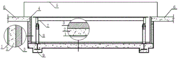
Fig. 1 is the utility model discloses prefabricated component is gallery front structure schematic diagram for production line.
In the figure: 1. a moisture barrier; 2. A structural layer; 3. a heat-insulating layer; 4. preventing sundries from rolling into the stop strip; 5. a sliding folding maintenance cover; 6. a ground surface; 7. a mould table; 8. a guide support device; 9. a track beam.
Detailed Description
The present invention will be further explained with reference to the accompanying drawings:
as shown in fig. 1, the gallery for the prefabricated part production line comprises a flow production line and a gallery in which the production line runs, the gallery is of a U-shaped structure, the side surface and the bottom surface of the gallery are respectively composed of a moisture-proof layer 1, a structural layer 2 and a heat-insulating layer 3, the structural layer 2 and the moisture-proof layer 1 are arranged in sequence from outside to inside, the moisture-proof layer 1 is made of a flexible waterproof material, the structural layer 2 is formed by pouring concrete, the exposed surface of the concrete is a smooth surface, a track beam 9 for running of the flow production line is additionally arranged at the bottom of the structural layer 2 at the bottom of the gallery bottom surface according to needs, pre-buried iron or I-steel is arranged in the track beam 9, and the heat; the height of the ground 6 on the two sides of the tunnel is lower than the height of the top surface of the die table 7 when the flow production line runs, the width of the tunnel is larger than the width of the die table 7, the distance from the edge of the tunnel to the edge of the die table 7 is not more than 5 cm, the upper edges of the two sides of the tunnel are provided with stop bars 4 which are higher than the ground 6 and used for preventing sundries from rolling into, and the stop bars 4 used for preventing the sundries from rolling into are made of rubber materials; the tunnel bottom is equipped with two track roof beams that are used for the operation of mould platform 7, and mould platform 7 contacts with track roof beam 9 through direction strutting arrangement 8, and the folding maintenance cover 5 that supports of slip is set up directly to the upside in tunnel, and the folding maintenance cover 5 that supports of slip forms confined maintenance space with heat preservation 3.
The embodiment is only an illustration of the concept and implementation of the present invention, and is not a limitation, and the technical solution without substantial transformation is still within the protection scope under the concept of the present invention.
Claims (5)

1.一种预制构件生产线用坑道,包括流水生产线和生产线运行的坑道,其特征在于:所述坑道为U型结构,坑道上沿两侧地面高度低于流水生产线模台顶面高度,坑道宽度大于模台宽度,且坑道边沿到模台边沿距离不大于5厘米,坑道的两侧上边沿设置高于地面的防止杂物滚入档条;所述坑道侧面和底面均为防潮层、结构层、保温层组成,坑道底部设有两条用于模台运行的轨道梁,坑道正上侧设置滑动折叠养护罩。1. a tunnel for prefabricated component production line, comprising the tunnel of assembly line and production line operation, it is characterized in that: the tunnel is a U-shaped structure, and the height of the ground along both sides of the tunnel is lower than the top surface height of the die table of the assembly line, the width of the tunnel. It is larger than the width of the die table, and the distance from the edge of the tunnel to the edge of the die table is not more than 5 cm. The upper edges of both sides of the tunnel are set higher than the ground to prevent debris from rolling into the rail; the side and bottom surfaces of the tunnel are moisture-proof layers and structural layers. , composed of thermal insulation layer, there are two rail beams at the bottom of the tunnel for the operation of the mold table, and a sliding and folding curing cover is set on the upper side of the tunnel. 2.根据权利要求1所述的预制构件生产线用坑道,其特征在于:所述防潮层采用柔性防水材料。2 . The tunnel for a prefabricated component production line according to claim 1 , wherein the moisture-proof layer is made of flexible waterproof material. 3 . 3.根据权利要求1所述的预制构件生产线用坑道,其特征在于:所述结构层采用混凝土浇注而成。3 . The tunnel for a prefabricated component production line according to claim 1 , wherein the structural layer is formed by pouring concrete. 4 . 4.根据权利要求1所述的预制构件生产线用坑道,其特征在于:所述保温层采用铁皮复合岩棉后固定到结构层上。4 . The tunnel for a prefabricated component production line according to claim 1 , wherein the thermal insulation layer is fixed to the structural layer after using iron sheet composite rock wool. 5 . 5.根据权利要求1所述的预制构件生产线用坑道,其特征在于:所述防止杂物滚入档条采用橡胶材质制成。5 . The tunnel for a prefabricated component production line according to claim 1 , wherein the rails for preventing sundries from rolling in are made of rubber. 6 .
CN201920400950.1U 2019-03-27 2019-03-27 Tunnel for prefabricated part production line Expired - Fee Related CN210190132U (en)

Priority Applications (1)

Application Number Priority Date Filing Date Title
CN201920400950.1U CN210190132U (en) 2019-03-27 2019-03-27 Tunnel for prefabricated part production line

Applications Claiming Priority (1)

Application Number Priority Date Filing Date Title
CN201920400950.1U CN210190132U (en) 2019-03-27 2019-03-27 Tunnel for prefabricated part production line

Publications (1)

Publication Number Publication Date
CN210190132U true CN210190132U (en) 2020-03-27

Family

ID=69877269

Family Applications (1)

Application Number Title Priority Date Filing Date
CN201920400950.1U Expired - Fee Related CN210190132U (en) 2019-03-27 2019-03-27 Tunnel for prefabricated part production line

Country Status (1)

Country Link
CN (1) CN210190132U (en)

Similar Documents

Publication Publication Date Title
CN101906768B (en) Panel construction method of concrete faced rock-fill dam
CN103939114B (en) A kind of outstanding rail chassis lining construction method
KR101367657B1 (en) Method for constructing face slab of concrete face rockfill dam
CN107905254A (en) A construction method of integrated hydraulic inner formwork trolley for comprehensive pipe gallery support and formwork
CN106703834A (en) Secondary lining integral formworking construction method for tunnel with super-large cross section
CN106346595A (en) Vertical molding mold and system and application method for concrete utility tunnel
CN106182359A (en) The concrete list storehouse horizontal mould of pipe gallery, system and piping lane molding methods
CN105804395B (en) Stair continuously poured in one molding construction method based on monoblock type typified form
CN108979132A (en) Floor post-cast strip template support system
CN108342993B (en) Underwater bearing platform suspension supporting platform and construction method thereof
CN203307840U (en) Integral horizontal moving type formwork construction device for strip-shaped constant-cross-section concrete structure
CN108457243B (en) Construction method of a prefabricated concrete wave retaining wall
CN110344844B (en) A construction method for track wells in track engineering
CN104480915A (en) Reversal rail hydraulic climbing form for concrete pouring of high and steep slope
CN106836286A (en) Underground engineering assembly concrete air channel and its construction method
CN114059654A (en) Rapid construction method for improved AAO biological pond chamber jumping method of sewage treatment station
CN109236322A (en) It a kind of artificial bottom plate preventing soft-rock tunnel pucking and its constructs and method for maintaining
CN106930778B (en) A Concrete Lining Induced Joint Structure and Setting Method for Water Conveyance Tunnel
CN103669746B (en) The construction method of inverted roof heat-insulation system
CN111472812A (en) Construction method for filling and pouring concrete into inverted arch of tunnel
CN204662742U (en) The movable surface construction structure of a kind of pitched roof
CN107542065B (en) A kind of construction method of small steel mould flipping for high and steep chute
KR20130058135A (en) Method for constructing face slab of concrete face rockfill dam using rail integrated side form
CN110118093A (en) A construction method for tunnel water trench cable trough
CN105780975A (en) Control technology of partition board cracks

Legal Events

Date Code Title Description
GR01 Patent grant
GR01 Patent grant
CF01 Termination of patent right due to non-payment of annual fee

Granted publication date: 20200327

CF01 Termination of patent right due to non-payment of annual fee