CN210187555U - a coating device - Google Patents
a coating device Download PDFInfo
- Publication number
- CN210187555U CN210187555U CN201920738029.8U CN201920738029U CN210187555U CN 210187555 U CN210187555 U CN 210187555U CN 201920738029 U CN201920738029 U CN 201920738029U CN 210187555 U CN210187555 U CN 210187555U
- Authority
- CN
- China
- Prior art keywords
- hopper
- coating
- glue
- roll
- sheath
- Prior art date
- Legal status (The legal status is an assumption and is not a legal conclusion. Google has not performed a legal analysis and makes no representation as to the accuracy of the status listed.)
- Expired - Fee Related
Links
Images



Landscapes
- Coating Apparatus (AREA)
Abstract
The utility model relates to a coating device, including two risers of vertical setting, through the hopper of bolt fastening between the riser, connect the coating roll inside the hopper and the coating motor of being connected with the coating roll through the bearing, the hopper is the U word form, and this hopper bottom circular arc sets up with the coating roll is concentric, and the interval of hopper bottom circular arc and coating roll is 5mm, the hopper top sets up the coating mouth, the top of coating roll exceeds coating mouth 20~30mm, be fixed with scraper assembly on the hopper of coating mouth one side, the hopper bottom still is connected with the shunt. The utility model discloses can replace artifical automatic glue that adds, can avoid the interior glue of hopper direct and expose for a long time in the air, avoid glue to stew for a long time in the hopper, clean easily moreover.
Description
Technical Field
The utility model relates to a coating technology field, in particular to coating device.
Background
The coating mechanism of the coating machine is suitable for coating glue, ink or other materials with certain effects on coiled substrates so as to be beneficial to printing or improve the paper quality. The coating mechanism of the coating machine mostly adopts a back roll reverse rotation mode to work, so that the coating efficiency can be effectively improved, and a large amount of manpower and material resources are saved. The existing coating machine adopts manual glue adding, a coating roll is placed in a hopper filled with glue, one part of the coating roll is soaked in the glue, the coating roll rotates to wrap the glue on the roll, and the coating is realized by contacting with a film material and cloth, but the vertical distance between the coating roll and the hopper is too large, after the glue in the hopper is partially used, the liquid level of the glue is positioned below the coating roll, so that the coating production is interrupted, and part of the unused glue in the hopper exists. Moreover, the existing hoppers are all open, i.e. hoppers without a top cover, which can cause direct and long-term exposure of the glue to the air, affecting the quality of the glue. And because glue has the adhesion, glue can adhere on the hopper inner wall, is difficult to clean, can lead to like this after adding new glue, and the quality of new glue can be influenced to old glue in the hopper.
Disclosure of Invention
The utility model aims at making improvement and innovation to the shortcoming that exists in the background art with not enough, providing a coating unit, this coating equipment can replace artifical automatic glue that adds, can avoid the hopper internal glue direct and expose for a long time in the air, avoids glue to stew for a long time in the hopper, and is clean easily moreover.
In order to achieve the above purpose, the technical scheme of the utility model is that: the utility model provides a coating device, includes two risers of vertical setting, through the hopper of bolt fastening between the riser, the coating motor that connects at the inside spreader roll of hopper and be connected with the spreader roll through the bearing, the hopper is the U word form, and this hopper bottom circular arc sets up with the spreader roll is concentric, and the interval of hopper bottom circular arc and spreader roll is 5mm, the hopper top sets up the coating mouth, the top of spreader roll exceeds coating mouth 20~30mm, be fixed with the scraper subassembly on the hopper of coating mouth one side, the hopper bottom still is connected with the shunt. By arranging the hopper with the arc-shaped bottom and reducing the distance between the coating roller and the bottom of the hopper to 5mm, the coating roller can completely utilize the glue in the hopper, so that the problem that the coating roller cannot contact with the glue when the liquid level of the glue is too low and the glue is kept stand in the hopper for a long time is avoided. One side of a coating port at the top of the hopper is a top plate integrally formed with the hopper, one side of the coating port is a scraper component, the distance between the top plate and the coating roll is 5-10 mm, the top plate, the scraper component and the coating roll are used for realizing the capping of the hopper, only a gap for the rotation of the coating roll is reserved, and the glue quality is prevented from being influenced by the fact that the glue is directly exposed in the air. Through glue-pouring machine and shunt, utilize controller control, can realize adding glue voluntarily, reduce the human cost, reduce intensity of labour.
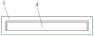
In one embodiment, the scraper assembly comprises a sheath fixed on the hopper through bolts and a scraper inserted into the sheath, the sheath is in a flat box shape lacking a narrow end face, one end of the scraper is welded with a screw rod, the screw rod penetrates through the sheath, and a nut is connected to the screw rod outside the sheath in a threaded mode. And the screw and the nut are used for controlling the scraper to advance and retreat, adjusting the distance between the scraper and the coating roller and controlling the coating thickness of the glue.
In one embodiment, the flow divider comprises flow dividing pipes, output pipes and input pipes, wherein the output pipes are uniformly arranged along the length direction of the flow dividing pipes, the input pipes are arranged on the flow dividing pipes, the output pipes and the input pipes are integrally formed, at least one output pipe is arranged on the output pipes and connected with the bottom of the hopper, and the input pipes are connected with a glue filling machine through hoses. Because glue is thick, and mobility is poor, utilizes the shunt to divide into the glue of glue filling machine output into the multistrand and pours into the hopper into simultaneously, can guarantee the glue evenly distributed in the hopper, avoids glue to pile up and leads to glue coating inequality.
In one embodiment, the input pipe device is connected with a glue-pouring machine through a hose, and the glue-pouring machine is independently arranged outside the coating machine.
In one embodiment, a teflon coating is sprayed on the inner wall of the hopper. The Teflon coating is sprayed on the inner wall of the hopper, and the hopper is easy to clean due to the fact that Teflon has the characteristic of non-stickiness.
The utility model has the advantages and beneficial effect:
the utility model discloses a set up the hopper of convex bottom to reduce the distance to 5mm of coating roll and hopper bottom, make the glue in the complete utilization hopper of coating roll ability, and then avoid when the glue liquid level crosses low, the coating roll can't contact with glue, and make glue stew in the hopper for a long time. Meanwhile, the top plate, the scraper component and the coating roll which are integrally formed with the hopper realize the sealing cover of the hopper, only a gap for the rotation of the coating roll is reserved, and the glue quality is prevented from being influenced by the fact that the glue is directly exposed in the air. Through glue-pouring machine and shunt, utilize controller control, can realize adding glue voluntarily, reduce the human cost, reduce intensity of labour. The Teflon coating is sprayed on the inner wall of the hopper, and the hopper is easy to clean due to the fact that Teflon has the characteristic of non-stickiness.
Drawings
Fig. 1 is a schematic view of the present invention;
FIG. 2 is a schematic view of a coating apparatus;
FIG. 3 is a schematic view of a spatula and sheath;
FIG. 4 is a schematic view of a hopper;
in the figure: the device comprises a vertical plate 1, a hopper 2, a coating roller 3, a scraper 4, a sheath 5, a screw 6, a coating motor 7, a flow divider 8, an output pipe 9, a glue pouring machine 10, a coating port 11, a flow dividing pipe 12 and an input pipe 13.
Detailed Description
In order to facilitate understanding of the present invention, the present invention will be described more fully hereinafter with reference to the accompanying drawings. Preferred embodiments of the present invention are shown in the drawings. The invention may, however, be embodied in many different forms and should not be construed as limited to the embodiments set forth herein. Rather, these embodiments are provided so that this disclosure will be thorough and complete.
It will be understood that when an element is referred to as being "disposed" or "connected" to another element, it can be directly disposed or connected to the other element or intervening elements may also be present.
Unless defined otherwise, all technical and scientific terms used herein have the same meaning as commonly understood by one of ordinary skill in the art to which this invention belongs. The terminology used in the description presented herein is for the purpose of describing particular embodiments only and is not intended to be limiting of the invention.
In fig. 1-4: the device comprises a vertical plate 1, a hopper 2, a coating roller 3, a scraper 4, a sheath 5, a screw 6, a coating motor 7, a flow divider 8, an output pipe 9, a glue pouring machine 10, a coating port 11, a flow dividing pipe 12 and an input pipe 13.
As shown in fig. 1-4, a hopper 2 is fixed between two vertical plates 1 which are vertically arranged, an applicator roll 3 is connected in the hopper 2 through a bearing, an applicator motor 7 is connected on the applicator roll 3, the hopper 2 is U-shaped, a layer of Teflon coating 30 is sprayed on the inner wall of the hopper 2, the bottom arc of the hopper 2 and the coating roller 3 are concentrically arranged, the distance between the bottom arc of the hopper 2 and the coating roller 3 is 5mm, a coating port 11 is arranged at the top of the hopper 2, a top plate which is integrally formed with the hopper 2 is arranged at one side of the coating port 11 at the top of the hopper 2, a scraper component is arranged at one side, and the distance between the top plate and the coating roll 3 is 5-10 mm, the distance between the top plate and the coating roll 3 is 10mm in the embodiment, the top plate, the scraper component and the coating roll 3 are utilized to realize the capping of the hopper 2, only the gap for the rotation of the coating roll 3 is reserved, and the glue quality is prevented from being influenced by the fact that the glue is directly exposed in the air. The vertical distance between the top of the coating roller 3 and the coating outlet 11 is 20-30 mm, the vertical distance between the top of the coating roller 3 and the coating outlet 11 in the embodiment is 30mm, when a film or an adhesive tape passes through the coating roller 3 and is coated with glue, the distance between the film or the adhesive tape and the hopper 2 is ensured to be 30mm, and the film or the adhesive tape is prevented from being scratched and rubbed with the hopper 2. Be fixed with the scraper subassembly on the hopper 2 of coating mouth 11 one side, the scraper subassembly includes sheath 5 and the scraper 4 of pegging graft in sheath 5 of fixing on hopper 2 through the bolt, and sheath 5 is the flat box-like that lacks a narrow terminal surface, and the welding has screw rod 6 in the one end of scraper 4, and this screw rod 6 runs through sheath 5 and sets up to threaded connection has the nut on the screw rod 6 of sheath 5 outside. Still be connected with shunt 8 in hopper 2 bottom, shunt 8 has glue-pouring machine 10 through hose connection, and this glue-pouring machine 10 sets up at the coating machine outside independently. Shunt 8 includes shunt tubes 12, along 12 length direction align to grid output tube 9 that set up of shunt tubes and the input tube 13 of setting on shunt tubes 12, output tube 9 and the setting of input tube 13 integrated into one piece, output tube 9 sets up 3 at least to be connected with 2 bottoms of hopper, output tube 9 sets up 7 in this implementation, and input tube 13 has glue filling machine 10 through hose connection moreover, and liquid filling machine 26 purchases the income through market.
The utility model discloses a theory of operation is: under the control of an external controller, the glue filling machine 10 adds glue into the hopper 2 at a set speed, and ensures that the glue is in the hopper 2 at any time, the coating roller 3 is soaked in the glue, the coating motor 7 drives the coating roller 3 to rotate in the opposite direction of the movement of the film material or the adhesive tape at a set rotating speed, the glue is wrapped on the coating roller 3, and then the glue is coated on the film material or the adhesive tape.
The embodiments of the present invention are only descriptions of the preferred embodiments of the present invention, not right the concept and scope of the present invention are limited, and the technical personnel in the field are right the various modifications and improvements made by the technical solution of the present invention without departing from the design concept of the present invention, all fall into the protection scope of the present invention, the technical contents claimed by the present invention are all recorded in the claims.
Claims (5)
1. A coating apparatus, characterized in that: including two blocks of risers (1) of vertical setting, through hopper (2) of bolt fastening between riser (1), coating roll (3) inside hopper (2) and coating motor (7) of being connected with coating roll (3) are connected through the bearing, hopper (2) are the U word form, and this hopper (2) bottom circular arc sets up with coating roll (3) with one heart, and the interval of hopper (2) bottom circular arc and coating roll (3) is 5mm, hopper (2) top sets up coating mouth (11), the top of coating roll (3) exceeds coating mouth (11) 20~30mm, be fixed with scraper assembly on hopper (2) of coating mouth (11) one side, hopper (2) bottom is connected with shunt (8).
2. A coating apparatus according to claim 1, wherein said doctor assembly comprises a sheath (5) bolted to the hopper (2) and a doctor blade (4) inserted into the sheath (5), said sheath (5) having a flat box shape lacking a narrow end face, a screw (6) is welded to one end of said doctor blade (4), said screw (6) is disposed through the sheath (5), and a nut is threadedly connected to the screw (6) outside the sheath (5).
3. A coating apparatus according to claim 1, wherein said flow divider (8) comprises flow dividing tubes (12), outlet pipes (9) arranged in a uniform manner along the length of the flow dividing tubes (12), and inlet pipes (13) arranged on the flow dividing tubes (12), said flow dividing tubes (12), outlet pipes (9), and inlet pipes (13) being integrally formed, and at least 3 outlet pipes (9) being arranged and connected to the bottom of the hopper (2).
4. A coating device according to claim 3, characterized in that said input pipe (13) is connected to a glue-pouring machine (10) by means of a hose, which glue-pouring machine (10) is arranged separately outside the coating machine.
5. A coating device according to claim 1, characterized in that said hopper (2) has a teflon coating (30) applied to its inner wall.
Priority Applications (1)
| Application Number | Priority Date | Filing Date | Title |
|---|---|---|---|
| CN201920738029.8U CN210187555U (en) | 2019-05-22 | 2019-05-22 | a coating device |
Applications Claiming Priority (1)
| Application Number | Priority Date | Filing Date | Title |
|---|---|---|---|
| CN201920738029.8U CN210187555U (en) | 2019-05-22 | 2019-05-22 | a coating device |
Publications (1)
| Publication Number | Publication Date |
|---|---|
| CN210187555U true CN210187555U (en) | 2020-03-27 |
Family
ID=69874730
Family Applications (1)
| Application Number | Title | Priority Date | Filing Date |
|---|---|---|---|
| CN201920738029.8U Expired - Fee Related CN210187555U (en) | 2019-05-22 | 2019-05-22 | a coating device |
Country Status (1)
| Country | Link |
|---|---|
| CN (1) | CN210187555U (en) |
Cited By (1)
| Publication number | Priority date | Publication date | Assignee | Title |
|---|---|---|---|---|
| CN121060761A (en) * | 2025-10-17 | 2025-12-05 | 江苏希诚新材料科技有限公司 | Coating device and coating method for conductive paste |
-
2019
- 2019-05-22 CN CN201920738029.8U patent/CN210187555U/en not_active Expired - Fee Related
Cited By (1)
| Publication number | Priority date | Publication date | Assignee | Title |
|---|---|---|---|---|
| CN121060761A (en) * | 2025-10-17 | 2025-12-05 | 江苏希诚新材料科技有限公司 | Coating device and coating method for conductive paste |
Similar Documents
| Publication | Publication Date | Title |
|---|---|---|
| CN207823307U (en) | A high-efficiency and energy-saving coating device for producing adhesive tape | |
| CN109876994B (en) | Bubble-free gravure coating device and coating process for aluminum plastic film | |
| CN204564454U (en) | Glue application device | |
| CN211587284U (en) | Cloth rubberizing device | |
| CN214812131U (en) | A paint device for metal surface | |
| CN112403843B (en) | A precise gluing device for corroded aluminum foil | |
| CN219965407U (en) | Self-adhesion type waterproof coiled material gluing device | |
| CN117019511A (en) | A battery pole piece coating adjustment device and its adjustment method | |
| CN104646237B (en) | A kind of apparatus for coating | |
| CN211756446U (en) | Membrane coating roll of precoating of gluey function is spouted in area | |
| CN220742187U (en) | Laminating machine for tarpaulin film | |
| CN217550244U (en) | Automatic glue device that evenly paints of binding dust pad | |
| CN206605890U (en) | A kind of glue spreading apparatus for being used to be combined tablecloth make-up machine | |
| CN217989864U (en) | Material tank for automatic dispenser | |
| CN217631083U (en) | Plastering device convenient to adjust and paint thickness | |
| CN210187554U (en) | a coating equipment | |
| CN116237201A (en) | An extrusion optical film coating production device | |
| CN221048641U (en) | Glue spreader for plywood production | |
| CN204933845U (en) | Adjustable positive and negative transition high-voltage cable asphalt coating unit | |
| CN223350604U (en) | A coating laminating machine for producing plaster | |
| CN211597594U (en) | A paint applicator for decoration | |
| CN209124248U (en) | A kind of discharging device convenient for adjusting the rubber adhesion promoting agent of height | |
| CN210940652U (en) | A gluing device for a box gluing machine | |
| CN223658554U (en) | A sealing device for solid dosage form packaging boxes | |
| CN209864672U (en) | Medicinal sugar-coating machine |
Legal Events
| Date | Code | Title | Description |
|---|---|---|---|
| GR01 | Patent grant | ||
| GR01 | Patent grant | ||
| EE01 | Entry into force of recordation of patent licensing contract | ||
| EE01 | Entry into force of recordation of patent licensing contract |
Assignee: Hunan Senyan polymer new material Co.,Ltd. Assignor: Hunan Province Puruida Interior Material Co.,Ltd. Contract record no.: X2023980049283 Denomination of utility model: A coating device Granted publication date: 20200327 License type: Common License Record date: 20231204 |
|
| CF01 | Termination of patent right due to non-payment of annual fee | ||
| CF01 | Termination of patent right due to non-payment of annual fee |
Granted publication date: 20200327 |