Assembly type composite structure dense rib floor
Technical Field
The utility model relates to a superstructure, concretely relates to assembled integrated configuration close rib superstructure belongs to building engineering technical field.
Background
The cast-in-place integral floor system has good integrity and strong anti-seismic performance and is widely used in common reinforced concrete structures. But the on-site wet operation is more, the self weight is great, the working procedure is complex, the construction period is long, and a large amount of templates are required on the site; in addition, the concrete slab bottom is easy to crack, the floor slab span is limited, and the column net is too dense.
The assembled floor has the advantages of high construction speed, neat construction site, building material saving, high industrialization degree and the like, and the assembled floor is increasingly used in practical engineering; the existing fabricated floor system mostly adopts a steel bar truss floor bearing plate, a profiled steel sheet combined floor slab or a laminated slab. The composite structure is used for exerting the advantages of steel and concrete, reducing the self weight of the floor, and having certain economic benefit compared with steel floors.
However, the problems of overlarge prefabricated components, difficulty in transportation, unreliable connection between concrete and steel, poor overall performance, poor anti-seismic performance and the like exist in the application of the conventional assembled composite floor system.
SUMMERY OF THE UTILITY MODEL
Not enough to above-mentioned prior art, the utility model aims to a connecting rod and combination girder steel through prefabricated floor cover plate are connected. The structural strength of the integral composite floor system is improved, the anti-seismic performance is improved, and the transportation convenience of the prefabricated floor cover plate is improved. The utility model provides an assembled integrated configuration close rib superstructure, this assembled integrated configuration close rib superstructure includes: combining steel beams and prefabricating a floor slab; the periphery of the prefabricated floor slab is arranged on the combined steel beam; the combined steel beam is connected with the concrete column; prefabricated floor slab includes: a cover plate main body and a connecting rod; the middle section of the connecting rod is arranged in the cover plate main body, and two ends of the connecting rod extend out of the cover plate main body; the two ends of the connecting rod are connected with the combined steel beam.
According to the utility model discloses an embodiment provides an assembled integrated configuration close rib superstructure:
the utility model provides an assembled integrated configuration close rib superstructure, this assembled integrated configuration close rib superstructure includes: combining steel beams and prefabricating a floor slab; the periphery of the prefabricated floor slab is arranged on the combined steel beam; the combined steel beam is connected with the concrete column; prefabricated floor slab includes: a cover plate main body and a connecting rod; the middle section of the connecting rod is arranged in the cover plate main body, and two ends of the connecting rod extend out of the cover plate main body; the two ends of the connecting rod are connected with the combined steel beam.
Preferably, the periphery of the prefabricated floor slab is arranged on the combined steel beam and specifically comprises the following steps: the combination girder steel includes: wing plates and web plates; the web plate is vertically arranged in the middle of the wing plate; the wing plates and the web plates are combined into an inverted T shape; the edge of the prefabricated floor slab is erected on the wing plate.
Preferably, the connection of the two ends of the connecting rod and the combined steel beam is specifically as follows: two ends of the connecting rod are provided with thread structures; the web plate is provided with a mounting groove corresponding to the connecting rod; the end part of the connecting rod is erected in the mounting groove; the screw thread structure on the connecting rod clamps the webs at the two ends of the connecting rod through matching with the nut, and fixes the connecting rod and the combined steel beam.
Preferably, the setting of the interlude of connecting rod is specifically: the edge of the cover plate main body is provided with a convex part and a concave part; the convex parts and the concave parts are arranged at intervals; the connecting rod is prefabricated in the cover plate main body, and two ends of the connecting rod extend out of the protruding part of the cover plate main body; the convex parts of the prefabricated floor plates on two sides of the same web plate are staggered with each other.
Preferably, the prefabricated floor slab further comprises: a reinforcing bar rod; the reinforcing rib rods penetrate through the protruding parts at the edges of the prefabricated floor slabs; and the reinforcing bar rods are connected with the concrete columns at the two ends of the edge of the prefabricated floor slab.
Preferably, the composite steel beam further comprises: the side supporting plates are arranged at two ends of the wing plates and the web plates; the side supporting plate is connected with the concrete column in a propping mode.
Preferably, the composite steel beam further comprises: a stud; the pegs are vertically arranged on the wing plates and are positioned between the edges of the prefabricated floor slab and the web plate.
Preferably, the number of the studs between each protruding part and the web is A, the number of the studs between the recessed parts at the edges of the prefabricated floor slab and the web is B, and B is larger than or equal to A; preferably, B is 2 to 4 and A is 1 to 2.
Preferably, the connecting rod is a steel bar, preferably a prestressed steel bar.
Preferably, the assembled composite structure multi-ribbed floor further comprises: steel corbels; the steel corbel includes: the column wrapping cylinder, the bearing plate and the bearing rib plate are arranged; the steel bracket is sleeved on the concrete steel column through the column wrapping cylinder; the bearing plate is arranged at the upper end of the column wrapping barrel; the bearing rib plates are connected with the lower end face of the bearing plate and the side face of the column wrapping barrel; the bearing plate is arranged below the joint of the combined steel beam and the concrete column, the upper surface of the bearing plate is connected with the lower surface of the combined steel beam, and the inner surface of the column wrapping cylinder is connected with the outer surface of the concrete steel column.
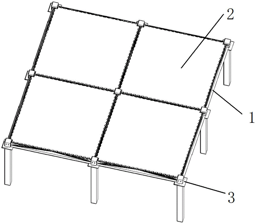
The utility model discloses in, combination girder steel level sets up. The two ends of the combined steel beam are connected with the concrete columns. The combined steel beams are connected end to end through concrete columns. The steel beams are combined to form a rectangular frame. That is, the rectangular frame has two pairs of parallel combined steel beams. The prefabricated floor slab is erected on a rectangular frame formed by the combined steel beams. The pre-branch floor covering includes: apron main part, connecting rod. The cover plate main body is a multi-ribbed precast slab, namely, a plurality of rib beams are arranged at the bottom of the cover plate main body. The connecting rod is worn to establish in the apron main part, and the connecting rod is parallel with the apron main part. The connecting rod extends out of the cover plate main body and is perpendicular to the edge of the cover plate main body. The connecting rods are divided into two groups. The two groups of connecting rods are mutually vertical. Two sets of connecting rods are connected perpendicularly respectively in the two pairs of parallel combination girder steels in the apron main part outside. The connecting rod in the prefabricated floor cover plate is connected with the combined steel beam, so that the structural strength of the floor system on the horizontal plane is improved. The building has good overall performance and better earthquake resistance. Meanwhile, the connecting rods penetrate through the cover plate main body, so that the overall structural strength of the prefabricated floor cover plate is improved, and the toughness of the prefabricated floor cover plate stressed in the vertical direction is improved.
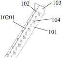
The utility model discloses in, the combination girder steel includes: a wing and a web. The wing plates are horizontally arranged. The web is arranged above the wing plate along the direction of the wing plate and perpendicular to the wing plate. The web plate and the wing plate form an inverted T-shaped steel beam. Because the edge of the prefabricated floor slab is erected on the wing plate of the combined steel beam. The pterygoid lamina of the rectangular frame that the combination girder steel becomes plays the effect of support to prefabricated floor board.
The utility model discloses in, the both ends of connecting rod are provided with helicitic texture, and after the helicitic texture at connecting rod both ends passed the web at prefabricated floor board both ends, through helicitic texture and nut cooperation for the web of connecting rod and combination girder is at the orientation of connecting rod fixed connection. Thereby make prefabricated floor board and combination girder steel at connecting rod direction fixed connection. Because there are two sets of mutually perpendicular's connecting rod and combination girder steel to pass through helicitic texture fixed connection in prefabricated floor board. Thereby make prefabricated floor board and combination girder steel rigid fixation connect on the horizontal plane. Thereby improving the structural rigidity of the integral floor slab. And meanwhile, the prefabricated floor slab is convenient to disassemble, and the prefabricated floor slab can be upwards detached from the rectangular frame formed by the combined steel beams only by loosening the nuts during disassembly.
It is further noted that the web is provided with an installation groove. The opening of the mounting groove is vertically upward. The web is connected with the connecting rod through the mounting groove. The positions of the installation grooves of the web plates correspond to the connecting rods one by one. Prefabricated floor board sets up behind the pterygoid lamina, and the connecting rod is contradicted on the mounting groove, has played the effect of certain sharing gravity. In addition, due to the existence of the mounting groove, the prefabricated floor slab is very convenient to mount, namely, the prefabricated floor slab is placed from top to bottom only by aligning the opening positions of the connecting rod and the mounting groove, and the prefabricated floor slab can be accurately mounted in the rectangular frame formed by the combined steel beams.
The utility model discloses in, the edge of the apron main part of prefabricated floor slab is provided with bulge and depressed part, and bulge and depressed part interval set up. I.e. the projection is located at the headspace between the edge of the cover body and the web. After the prefabricated floor slab and the combined steel beam are fixedly installed, concrete is cast in the reserved space between the edge of the slab main body and the web plate, and the structural strength between the prefabricated floor slab and the combined steel beam is increased and improved. Because the edge of apron main part is provided with the bulge, can be so that the connection structure of concrete and prefabricated floor board of pouring now is inseparabler.
It should be further noted that, the connecting rod specifically protrudes from the protruding portion of the cover plate main body, and the protruding portion is rectangular or semicircular in cross section. The connecting rods of the prefabricated floor cover plates on the two sides of the same combined steel beam and the connecting parts of the web plates of the combined steel beam are staggered mutually.
The utility model discloses in, prefabricated floor slab still includes: the reinforcing bar pole. The reinforcing rib rod penetrates through the protruding part of the cover plate main body. Parallel to the edges of the prefabricated floor covering. The prefabricated floor slab is rectangular in four sides, namely each prefabricated floor slab is provided with four reinforcing rib rods. The reinforcing bar rod is connected with the concrete columns at the two ends of the edge of the prefabricated floor slab. And the part of the reinforcing bar rod exposed out of the bulge is positioned in the area of the cast-in-place concrete. Therefore, the reinforcing rib rods strengthen the structural connection strength of the prefabricated floor slab and the cast-in-place concrete, and the prefabricated floor slab is connected with the concrete column. The structural strength of the integral floor system is also enhanced.
The utility model discloses in, the collateral branch backup pad sets up the both ends of whole combination girder steel, and the end connection of the web of collateral branch backup pad and combination girder steel and pterygoid lamina. The combined steel beam is connected with the concrete column through the side supporting plate.
In the utility model, the peg is arranged on the wing plate. Namely, the pin is fixedly arranged on the wing plate, or the pin is detachably arranged on the wing plate. The peg is located between the edge of prefabricated floor slab and the web, i.e. is arranged in the area of the cast-in-place concrete. The stud can make cast in situ concrete and pterygoid lamina be connected more closely in vertical direction, has strengthened cast in situ concrete promptly and has made up the structural strength that the girder steel is connected.
The utility model discloses in, steel bracket sets up on concrete column, is located the rectangle frame below that the combination girder steel formed. The weight of the whole pre-support floor slab can be effectively supported. The longitudinal structural strength of the whole floor slab is improved.
Due to the adoption of the design of the combined floor system, if the building needs to be dismantled in the later period, the part of cast-in-place concrete can be knocked out, and after connecting rods for connecting the prefabricated floor cover plate and the combined steel beams are cut off, the prefabricated floor cover plate and the combined steel beams can be separated and dismantled. The recovery of production data such as steel is convenient.
Compared with the prior art, the utility model discloses following beneficial effect has:
1. compared with the prior art, the scheme provided by the invention improves the integral structural strength of the floor system. The building has good overall performance and better anti-seismic performance;
2. compared with the prior art, the scheme provided by the invention has a matching structure which is easier to install, so that the overall construction speed is high;
3. compared with the prior art, the scheme provided by the invention is beneficial to the removal of the floor plate in the later period and is convenient for recovering production data.
Drawings
FIG. 1 is a top view of the assembled composite structure dense-rib floor system according to the embodiment of the present invention;
FIG. 2 is a schematic view of the junction of an assembled composite structure multi-ribbed floor in the embodiment of the present invention;
FIG. 3 is a schematic connecting rod connecting view of an assembled composite structure dense-rib floor system in the embodiment of the present invention;
FIG. 4 is a schematic view of a composite steel beam of the prefabricated composite structure multi-ribbed floor system according to the embodiment of the present invention;
FIG. 5 is a detail view of the assembled steel beam of the prefabricated multi-ribbed floor system in the embodiment of the present invention;
FIG. 6 is a schematic structural view of a steel corbel of an assembled composite-structure multi-ribbed floor according to an embodiment of the present invention;
fig. 7 is the whole structure bottom view of the assembled composite structure dense-rib floor system in the embodiment of the utility model.
Reference numerals:
1: combining the steel beams; 101: a wing plate; 102: a web; 10201: mounting grooves; 103: side supporting plates; 104: a stud; 2: prefabricating a floor slab; 201: a cover plate main body; 202: a connecting rod; 20201: a thread structure; 203: a projection; 204: a recessed portion; 205: a reinforcing bar rod; 3: steel corbels; 301: wrapping a column barrel; 302: a support plate; 303: a load-bearing rib plate.
Detailed Description
According to the utility model discloses an embodiment provides an assembled integrated configuration close rib superstructure:
the utility model provides an assembled integrated configuration close rib superstructure, this assembled integrated configuration close rib superstructure includes: the method comprises the following steps of (1) combining steel beams and prefabricating a floor slab (2); the periphery of the prefabricated floor slab 2 is arranged on the combined steel beam 1; the combined steel beam 1 is connected with the concrete column; prefabricated floor slab 2 includes: a cover plate main body 201 and a connecting rod 202; the middle section of the connecting rod 202 is arranged in the cover plate main body 201, and two ends of the connecting rod 202 extend out of the cover plate main body 201; both ends of the connecting rod 202 are connected with the combined steel beam 1.
Preferably, the periphery of the prefabricated floor slab 2 is arranged on the combined steel beam 1, and specifically comprises the following steps: the combination steel beam 1 includes: wing plate 101, web 102; the web plate 102 is vertically arranged in the middle of the wing plate 101; the wing plate 101 and the web plate 102 are combined into an inverted T shape; the edge of the prefabricated floor slab 2 is erected on the wing plate 101.
Preferably, the connection between the two ends of the connecting rod 202 and the combined steel beam 1 is specifically: two ends of the connecting rod 202 are provided with thread structures 20201; a mounting groove 10201 is arranged on the web plate 102 corresponding to the connecting rod 202; the end of the connecting rod 202 is arranged in the mounting groove 10201; the thread structure 20201 on the connecting rod 202 fixes the connecting rod 202 and the composite steel beam 1 by clamping the webs 102 at both ends of the connecting rod 202 in cooperation with nuts.
Preferably, the middle section of the connecting rod 202 is disposed in the cover plate main body 201, specifically: the edge of the cover plate main body 201 is provided with a convex part 203 and a concave part 204; the convex part 203 and the concave part 204 are arranged at intervals; the connecting rod 202 is prefabricated in the cover plate main body 201, and two ends of the connecting rod 202 extend out of the convex part 203 of the cover plate main body 201; the projections 203 of the prefabricated floor covering panels 2 on both sides of one and the same web 102 are offset from each other.
Preferably, the prefabricated floor slab 2 further comprises: a reinforcing bar rod 205; the reinforcing bar rod 205 is arranged on the bulge part 203 at the edge of the prefabricated floor slab 2 in a penetrating way; and the reinforcing bar rods 205 are connected with the concrete columns at the two ends of the edge of the prefabricated floor slab 2.
Preferably, the combined steel beam 1 further includes: side support plates 103, the side support plates 103 being disposed at both ends of the wing plate 101 and the web 102; the side supporting plate 103 is connected with the concrete column in a propping mode.
Preferably, the combined steel beam 1 further includes: a peg 104; the peg is arranged vertically on the wing 101 and the peg 104 is located between the edge of the prefabricated floor slab 2 and the web 102.
Preferably, the number of the studs between each convex part 203 and the web plate 102 is A, the number of the studs between the concave part 204 at the edge of the prefabricated floor slab 2 and the web plate 102 is B, and B is more than or equal to A; preferably, B is 2 to 4 and A is 1 to 2.
Preferably, the connecting rod 202 is a steel bar, preferably a prestressed steel bar.
Preferably, the assembled composite structure multi-ribbed floor further comprises: a steel corbel 3; the steel bracket 3 includes: column wrapping barrel 301, supporting plate 302 and bearing rib plate 303; the steel bracket 3 is sleeved on the concrete steel column through a column wrapping cylinder 301; the bearing plate 302 is arranged at the upper end of the column wrapping barrel 301; the bearing rib plates 303 are connected with the lower end face of the bearing plate 302 and the side face of the column wrapping barrel 301; the bearing plate 302 is arranged below the joint of the combined steel beam 1 and the concrete column, the upper surface of the bearing plate 302 is connected with the lower surface of the combined steel beam 1, and the inner surface of the column wrapping barrel 301 is connected with the outer surface of the concrete steel column.
Example 1
The utility model provides an assembled integrated configuration close rib superstructure, this assembled integrated configuration close rib superstructure includes: the method comprises the following steps of (1) combining steel beams and prefabricating a floor slab (2); the periphery of the prefabricated floor slab 2 is arranged on the combined steel beam 1; the combined steel beam 1 is connected with the concrete column; prefabricated floor slab 2 includes: a cover plate main body 201 and a connecting rod 202; the middle section of the connecting rod 202 is arranged in the cover plate main body 201, and two ends of the connecting rod 202 extend out of the cover plate main body 201; both ends of the connecting rod 202 are connected with the combined steel beam 1.
Example 2
Repeat embodiment 1, only the setting is specifically as on combination girder steel 1 around prefabricated floor board 2: the combination steel beam 1 includes: strake 101, web 102. The web 102 is vertically disposed in the middle of the wing plate 101. The wing 101 and the web 102 are combined into an inverted "T" shape. The edge of the prefabricated floor slab 2 is erected on the wing plate 101.
Example 3
Embodiment 2 is repeated except that the connection of the two ends of the connecting rod 202 and the combined steel beam 1 is specifically as follows: two ends of the connecting rod 202 are provided with thread structures 20201; a mounting groove 10201 is arranged on the web plate 102 corresponding to the connecting rod 202; the end of the connecting rod 202 is arranged in the mounting groove 10201; the thread structure 20201 on the connecting rod 202 fixes the connecting rod 202 and the composite steel beam 1 by clamping the webs 102 at both ends of the connecting rod 202 in cooperation with nuts.
Example 4
Embodiment 3 is repeated, except that the middle section of the connecting rod 202 is arranged in the cover plate main body 201, specifically: the edge of the cover plate main body 201 is provided with a convex part 203 and a concave part 204; the convex part 203 and the concave part 204 are arranged at intervals; the connecting rod 202 is prefabricated in the cover plate main body 201, and two ends of the connecting rod 202 extend out of the convex part 203 of the cover plate main body 201; the projections 203 of the prefabricated floor covering panels 2 on both sides of one and the same web 102 are offset from each other.
Example 5
Example 4 is repeated, except that the prefabricated floor covering 2 further comprises: a stiffener bar 205. The reinforcing bar 205 is arranged through the protrusion 203 at the edge of the prefabricated floor covering 2. And the reinforcing bar rods 205 are connected with the concrete columns at the two ends of the edge of the prefabricated floor slab 2.
Example 6
Example 5 was repeated except that the composite steel beam 1 further included: side support plates 103, the side support plates 103 being disposed at both ends of the wing plate 101 and the web 102. The side supporting plate 103 is connected with the concrete column in a propping mode.
Example 7
Example 6 was repeated except that the composite steel beam 1 further included: a peg 104. The peg is arranged vertically on the wing 101 and the peg 104 is located between the edge of the prefabricated floor slab 2 and the web 102. The number of the studs between each convex part 203 and the web 102 is A, the number of the studs between the concave part 204 of the prefabricated floor slab 2 and the web 102 is B, and B is more than or equal to A. Preferably, B is 2 and A is 1.
Example 8
Example 7 is repeated except that the connecting rod 202 is a steel bar.
Example 9
Example 8 is repeated except that the tie bar 202 is a prestressed steel bar.
Example 10
Repeat embodiment 9, only assembled integrated configuration close rib superstructure still includes: a steel corbel 3; the steel bracket 3 includes: column wrapping barrel 301, supporting plate 302 and bearing rib plate 303; the steel bracket 3 is sleeved on the concrete steel column through a column wrapping cylinder 301; the bearing plate 302 is arranged at the upper end of the column wrapping barrel 301; the bearing rib plates 303 are connected with the lower end face of the bearing plate 302 and the side face of the column wrapping barrel 301; the bearing plate 302 is arranged below the joint of the combined steel beam 1 and the concrete column, the upper surface of the bearing plate 302 is connected with the lower surface of the combined steel beam 1, and the inner surface of the column wrapping barrel 301 is connected with the outer surface of the concrete steel column.