CN210170981U - A shampoo effluent filter device - Google Patents
A shampoo effluent filter device Download PDFInfo
- Publication number
- CN210170981U CN210170981U CN201920893268.0U CN201920893268U CN210170981U CN 210170981 U CN210170981 U CN 210170981U CN 201920893268 U CN201920893268 U CN 201920893268U CN 210170981 U CN210170981 U CN 210170981U
- Authority
- CN
- China
- Prior art keywords
- filter screen
- clamping part
- barrel
- locking portion
- ejection
- Prior art date
- Legal status (The legal status is an assumption and is not a legal conclusion. Google has not performed a legal analysis and makes no representation as to the accuracy of the status listed.)
- Expired - Fee Related
Links
Images
Landscapes
- Filtration Of Liquid (AREA)
Abstract
The utility model discloses a shampoo goes out liquid filter equipment, including shell, filter screen cylinder, filter screen, locking portion and clamping part, the shell includes barrel and ejection of compact lid, the filter screen cup joints on filter screen cylinder, be provided with the discharge gate on the ejection of compact lid, ejection of compact lid is screwed with filter screen cylinder and is connected, the barrel is provided with seal ring with ejection of compact lid junction, and locking portion locks the feed inlet and the charge-in pipeline of barrel, the clamping part sets up on the barrel, the clamping part is the clamping part, and the clamping part can inject out the edge of storage bucket to one side for whole filter equipment is the tilt state. The utility model discloses a combination of filter screen section of thick bamboo and filter screen makes the utility model discloses a filtration mesh number increase and hole reduce to better filter effect has been reached, the utility model discloses still include threaded structure's feed inlet and discharge gate for filter equipment's use is not restricted to in the shampoo production facility, but in addition the clamping part makes filter equipment centre gripping at a feed cylinder edge.
Description
Technical Field
The utility model relates to a filter equipment especially relates to a shampoo goes out liquid filter equipment.
Background
In the production process of the shampoo, a filter screen is generally arranged at a discharge port of a shampoo production device, the filter screen plays a role in filtering a finished shampoo product, but the filter device provided by the existing shampoo production device is simple in structure, the mesh number of the filter screen is small, the pores are large, and for the shampoo with small viscosity, the filter effect is not good, so that the finished shampoo product contains more impurities.
SUMMERY OF THE UTILITY MODEL
In order to solve the technical problems of simple structure, small mesh number of a filter screen and large pore size of the filter device equipped in the prior shampoo production device, the utility model provides a shampoo liquid filtering device, which comprises a shell, a filter screen cylinder, a filter screen, a locking part and a clamping part, wherein the shell comprises a cylinder body and a discharge cover body, the filter screen is sleeved on the filter screen cylinder, a discharge port is arranged on the discharge cover body, the discharge cover body is screwed and connected with the filter screen cylinder, a sealing gasket is arranged at the joint of the cylinder body and the discharge cover body, the locking part comprises a first locking part and a second locking part, the first locking part locks the joint of the cylinder body and the discharge cover body, the second locking part locks a feed port of the cylinder body and a feed pipeline, the clamping part is arranged on the cylinder body, a clamping groove is arranged on the clamping part, and the clamping groove can be obliquely inserted into the edge of a discharge barrel, so that the whole filtering device is in an inclined state, the feed inlet faces upwards, and the discharge outlet faces downwards.
The clamping part further comprises a base, the base is arranged on the outer surface of the barrel and is rotatably connected with the clamping part, and the base and the clamping part fix the relative positions of the base and the clamping part through bolts.
The internal surface and the surface of feed inlet and discharge gate all are provided with the screw thread, rethread second locking portion locks behind feed inlet and the charge-in pipeline threaded connection.
The first locking portion comprises a fixing ring and a locking bolt, the locking bolt is arranged on the fixing ring, the other side of the fixing ring corresponding to the locking bolt is a hinged portion, the fixing ring adjusts the opening and closing angle of the fixing ring through the hinged portion, then the locking bolt is screwed, and the fixing ring locks the joint of the barrel and the discharging cover body.
The filter screen can cup joint at the surface of a filter screen section of thick bamboo, also can cup joint at the internal surface of a filter screen section of thick bamboo, and original feed inlet becomes the discharge gate this moment, and original discharge gate becomes the feed inlet.
Advantageous effects
The utility model discloses a combination of filter screen section of thick bamboo and filter screen makes the utility model discloses a filtration mesh number increase and hole reduce to better filter effect has been reached, the utility model discloses still include threaded structure's feed inlet and discharge gate for filter equipment's use is not restricted to in the shampoo production facility, but in addition the clamping part makes filter equipment centre gripping at a feed cylinder edge.
Drawings
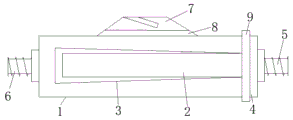
Fig. 1 is a schematic view of the present invention.
The labels in the figures are: 1-shell, 2-filter screen cylinder, 3-filter screen, 4-discharge cover body, 5-discharge hole, 6-feed inlet, 7-clamping part, 8-base and 9-first locking part.
Detailed Description
The invention will be further described with reference to the accompanying fig. 1 and the examples.
A shampoo liquid filtering device comprises a shell 1, a filtering screen cylinder 2, a filter screen 3, a locking part and a clamping part 7, the shell 1 comprises a cylinder body and a discharging cover body 4, the filter screen 3 is sleeved on the filter screen cylinder 2, the discharging cover body 4 is provided with a discharging port 5, the discharging cover body 4 is connected with the filter screen cylinder 2 in a screwing way, a sealing washer is arranged at the joint of the cylinder body and the discharge cover body 4, the locking part comprises a first locking part 9 and a second locking part, the first locking part 9 locks the joint of the cylinder body and the discharging cover body 4, the second locking part locks the feeding hole 6 of the cylinder body and the feeding pipeline, the clamping part 7 is arranged on the cylinder body, a clamping groove is arranged on the clamping part 7, the clamping groove can be obliquely inserted into the edge of the discharging barrel, so that the whole filtering device is in an inclined state, the feeding port 6 faces upwards, and the discharging port 5 faces downwards.
Clamping part 7 still includes base 8, base 8 sets up on the barrel surface, base 8 and clamping part 7 swivelling joint, and base 8 and clamping part 7 fix relative position between them through the bolt.
The inner surface and the outer surface of the feed inlet 6 and the discharge outlet 5 are both provided with threads, and the feed inlet 6 is in threaded connection with a feed pipeline and then locked by the second locking part.
The first locking portion 9 comprises a fixing ring and a locking bolt, the locking bolt is arranged on the fixing ring, the other side of the fixing ring corresponding to the locking bolt is a hinged portion, the fixing ring adjusts the opening and closing angle of the fixing ring through the hinged portion, then the locking bolt is screwed, and the fixing ring locks the joint of the barrel and the discharging cover body 4.
The filter screen 3 can be sleeved on the outer surface of the filter screen cylinder 2 and also can be sleeved on the inner surface of the filter screen cylinder 2, at the moment, the original feed port 6 is changed into a discharge port, and the original discharge port 5 is changed into a feed port.
Example 1
Before the filtering device is used, the filter screen 3 is sleeved on the filter screen cylinder 2, the cylinder body and the discharging cover body 4 are connected and locked through the first locking device, the sealing gasket at the joint keeps the sealing performance inside the filtering device, the feeding pipeline is connected and locked with the feeding port 6 through the second locking device, the discharging port 5 is fixedly connected through the corresponding locking device under the condition of being connected with other devices, the clamping part 7 of the clamping part 7 is obliquely inserted at the edge of the discharging barrel under the condition that the discharging port 5 is butted with the discharging barrel, and the clamping part 7 is connected with the base 8 through bolts, so that the whole filtering device can be fixed on the discharging barrel;
The above-mentioned embodiments only represent the preferred embodiments of the present invention, and the description thereof is more specific and detailed, but not to be construed as limiting the scope of the present invention. It should be noted that, for those skilled in the art, without departing from the spirit of the present invention, several changes, modifications and substitutions can be made, which are all within the scope of the present invention. Therefore, the protection scope of the present invention should be subject to the appended claims.
Claims (6)
1. A shampoo liquid filtering device is characterized in that: including shell, filter screen section of thick bamboo, filter screen, locking portion and clamping part, the shell includes barrel and ejection of compact lid, the filter screen cup joints on the filter screen section of thick bamboo, be provided with the discharge gate on the ejection of compact lid, ejection of compact lid is screwed with the filter screen section of thick bamboo and is connected, locking portion includes first locking portion and second locking portion, first locking portion locks barrel and ejection of compact lid junction, second locking portion locks the feed inlet and the charge-in pipeline of barrel, the clamping part sets up on the barrel, be provided with the centre gripping recess in the clamping part, the edge of storage bucket can be injected to one side to the centre gripping recess for whole filter equipment is the tilt state, and the feed inlet is towards the top, discharge gate below.
2. The shampoo outlet filtering device as claimed in claim 1, wherein: the clamping part further comprises a base, the base is arranged on the outer surface of the barrel and is rotatably connected with the clamping part, and the base and the clamping part fix the relative positions of the base and the clamping part through bolts.
3. The shampoo outlet filtering device as claimed in claim 1, wherein: the internal surface and the surface of feed inlet and discharge gate all are provided with the screw thread, rethread second locking portion locks behind feed inlet and the charge-in pipeline threaded connection.
4. The shampoo outlet filtering device as claimed in claim 1, wherein: the first locking portion comprises a fixing ring and a locking bolt, the locking bolt is arranged on the fixing ring, the other side of the fixing ring corresponding to the locking bolt is a hinged portion, and the fixing ring adjusts the opening and closing angle of the fixing ring through the hinged portion.
5. The shampoo outlet filtering device as claimed in claim 1, wherein: the filter screen can be sleeved on the outer surface of the filter screen cylinder and also can be sleeved on the inner surface of the filter screen cylinder.
6. The shampoo outlet filtering device as claimed in claim 1, wherein: and a sealing gasket is arranged at the joint of the cylinder body and the discharge cover body.
Priority Applications (1)
| Application Number | Priority Date | Filing Date | Title |
|---|---|---|---|
| CN201920893268.0U CN210170981U (en) | 2019-06-14 | 2019-06-14 | A shampoo effluent filter device |
Applications Claiming Priority (1)
| Application Number | Priority Date | Filing Date | Title |
|---|---|---|---|
| CN201920893268.0U CN210170981U (en) | 2019-06-14 | 2019-06-14 | A shampoo effluent filter device |
Publications (1)
| Publication Number | Publication Date |
|---|---|
| CN210170981U true CN210170981U (en) | 2020-03-24 |
Family
ID=69837474
Family Applications (1)
| Application Number | Title | Priority Date | Filing Date |
|---|---|---|---|
| CN201920893268.0U Expired - Fee Related CN210170981U (en) | 2019-06-14 | 2019-06-14 | A shampoo effluent filter device |
Country Status (1)
| Country | Link |
|---|---|
| CN (1) | CN210170981U (en) |
-
2019
- 2019-06-14 CN CN201920893268.0U patent/CN210170981U/en not_active Expired - Fee Related
Similar Documents
| Publication | Publication Date | Title |
|---|---|---|
| DE212022000294U1 (en) | Liquid supply device for sprayers | |
| CN206121279U (en) | Filter for field irrigation | |
| CN105782438B (en) | Double-cover pressure container | |
| CN207490171U (en) | A kind of new types of data module | |
| CN208415425U (en) | A kind of modified bilayer downspout device | |
| CN203886434U (en) | Preparation barrel | |
| CN210786481U (en) | A filter device for PCB board processing | |
| CN207694382U (en) | A kind of medical filter being conveniently replaceable filter core | |
| CN110015379A (en) | Drain plug device and discharge outlet open method and method for closing using it | |
| CN207042004U (en) | A kind of hydrotherapy pool internal circulation filtering device | |
| CN208583054U (en) | A solid-liquid separation device for medicine | |
| CN208525946U (en) | a filter device | |
| CN105480556B (en) | The interface sealing structure of device for storing liquid | |
| CN216919757U (en) | Water inlet structure of washing machine | |
| CN206434945U (en) | A kind of two-in-one strainer valve of Double-level Reticulated | |
| CN216333920U (en) | Double-thread cover structure of large rotational molding box body | |
| CN213296671U (en) | Fixing device for embedded part of integral-pouring filter plate | |
| CN212244538U (en) | Essential oil processing is with tree peony seed oil sealing device | |
| CN221156714U (en) | Ion exchange resin column structure for cytidine acid synthesis | |
| CN206485827U (en) | A kind of oil truck closure | |
| CN207654827U (en) | A kind of melt-blown filter | |
| CN204986206U (en) | Outlet fastener | |
| CN219118285U (en) | Water tank pressure seal head | |
| CN216457389U (en) | Coating packing filter | |
| CN2425696Y (en) | Pipe joint filter with improved structure |
Legal Events
| Date | Code | Title | Description |
|---|---|---|---|
| GR01 | Patent grant | ||
| GR01 | Patent grant | ||
| CF01 | Termination of patent right due to non-payment of annual fee | ||
| CF01 | Termination of patent right due to non-payment of annual fee |
Granted publication date: 20200324 |