CN210164284U - Support frame for hydraulic and hydroelectric engineering construction - Google Patents
Support frame for hydraulic and hydroelectric engineering construction Download PDFInfo
- Publication number
- CN210164284U CN210164284U CN201920851818.2U CN201920851818U CN210164284U CN 210164284 U CN210164284 U CN 210164284U CN 201920851818 U CN201920851818 U CN 201920851818U CN 210164284 U CN210164284 U CN 210164284U
- Authority
- CN
- China
- Prior art keywords
- support frame
- hydraulic
- bracing piece
- engineering construction
- support
- Prior art date
- Legal status (The legal status is an assumption and is not a legal conclusion. Google has not performed a legal analysis and makes no representation as to the accuracy of the status listed.)
- Expired - Fee Related
Links
- 238000010276 construction Methods 0.000 title claims abstract description 15
- 206010020649 Hyperkeratosis Diseases 0.000 claims description 8
- 229910000831 Steel Inorganic materials 0.000 claims description 3
- 239000003381 stabilizer Substances 0.000 claims description 3
- 239000010959 steel Substances 0.000 claims description 3
- 238000009434 installation Methods 0.000 abstract description 4
- 230000000694 effects Effects 0.000 description 3
- 230000009286 beneficial effect Effects 0.000 description 2
- 230000003139 buffering effect Effects 0.000 description 2
- 238000010586 diagram Methods 0.000 description 2
- 238000007726 management method Methods 0.000 description 2
- 239000000463 material Substances 0.000 description 2
- 238000012986 modification Methods 0.000 description 2
- 230000004048 modification Effects 0.000 description 2
- 241000826860 Trapezium Species 0.000 description 1
- 238000010923 batch production Methods 0.000 description 1
- 239000000284 extract Substances 0.000 description 1
- 238000004519 manufacturing process Methods 0.000 description 1
- 238000000034 method Methods 0.000 description 1
- 230000035939 shock Effects 0.000 description 1
- XLYOFNOQVPJJNP-UHFFFAOYSA-N water Substances O XLYOFNOQVPJJNP-UHFFFAOYSA-N 0.000 description 1
- 238000003466 welding Methods 0.000 description 1
Images



Landscapes
- Revetment (AREA)
Abstract
The utility model discloses a support frame is used in hydraulic and hydroelectric engineering construction, include: the supporting legs comprise an upper embedding column, a connecting rod and a lower embedding column, through holes are formed in the surface of the top plate, the upper embedding column is connected with the through holes in an embedding mode, a plurality of adjusting grooves are formed in the side wall of the upper embedding column, a supporting plate is connected to the side wall of the upper embedding column in an embedding mode, fixing rods are arranged on the left side and the bottom of the supporting plate, and the fixing rods are connected with the adjusting grooves in an embedding mode; the slot has been seted up at bottom plate top surface middle part, inlays down the post and inlays with the slot and be connected, and spherical groove has been seted up to the bottom surface of bottom plate, and spherical inslot level is fixed with support piece. The support frame of the utility model is not connected by bolts, the height is convenient to adjust, and the convenience of adjustment and installation is increased; set up spherical groove in the bottom plate, have certain support intensity, the netted support piece of cooperation can improve structural strength greatly, can also reduce its weight simultaneously, reduces the cost of transportation.
Description
Technical Field
The utility model relates to a support technical field, more specifically are a support for hydraulic and hydroelectric engineering construction.
Background
The culture of the hydraulic and hydroelectric engineering has knowledge in the aspects of exploration, planning, design, construction, scientific research, management and the like of the hydraulic and hydroelectric engineering, and can be used for high-level engineering technical talents working in the aspects of planning, design, construction, scientific research, management and the like in departments of water conservancy, hydropower and the like.
At present, the existing support frame has the following problems: (1) some support frames can be adjusted in height to a certain degree, but in the adjusting and installing process, a plurality of bolts need to be disassembled and installed by using a plurality of tools, and the operation is not convenient enough; (2) the support frame can make the steadiness of support frame lower after the height-adjusting, has increased the weight of bottom plate in order to guarantee the steadiness, has still increased the difficulty of transportation transport when having increased use cost. For this reason, a new scheme needs to be designed to give improvements.
SUMMERY OF THE UTILITY MODEL
An object of the utility model is to provide a support frame is used in hydraulic and hydroelectric engineering construction has solved the problem that proposes in the background art, satisfies the in-service use demand.
In order to achieve the above object, the utility model provides a following technical scheme: a support frame for hydraulic and hydroelectric engineering construction comprises: the supporting legs comprise an upper embedding column, a connecting rod and a lower embedding column, through holes are formed in the surface of the top plate, the upper embedding column is connected with the through holes in an embedding manner, a plurality of adjusting grooves are formed in the side wall of the upper embedding column, a supporting plate is connected to the side wall of the upper embedding column in an embedding manner, fixing rods are arranged on the left side and the bottom of the supporting plate, and the fixing rods are connected with the adjusting grooves in an embedding manner; the middle part of the top surface of the bottom plate is provided with a slot, the lower embedded column is connected with the slot in an embedded mode, the bottom surface of the bottom plate is provided with a spherical groove, and a support piece is horizontally fixed in the spherical groove.
As a preferred embodiment of the utility model, support piece wholly is netted, and support piece includes center block, longitudinal support pole, backup pad and horizontal bracing piece, the backup pad adopts the steel sheet to enclose to close and form and be the hexagon structure, the backup pad is equipped with three and size outside-in altogether and reduces in proper order.
As a preferred embodiment of the utility model, horizontal bracing piece is provided with six altogether, and horizontal bracing piece is connected with the center block, and six horizontal backup pads use the center block to distribute as central axial equidistance, the other end and the spherical inslot wall connection of horizontal bracing piece, just horizontal bracing piece and backup pad welded connection.
As a preferred embodiment of the utility model, the vertical setting of longitudinal support pole is in the junction of middle part backup pad and horizontal bracing piece, the longitudinal support pole extends and is connected with the callus on the sole to the backup pad below, the callus on the sole bottom surface is the level with the bottom plate bottom surface and aligns.
As an optimal implementation mode of the utility model, the slot bottom is provided with the rubber pad, the rubber pad top is provided with the lug that a plurality of equidistance distributes, inlay the post bottom surface down and seted up a plurality of and inlay the groove, the lug is connected with inlaying the groove.
Compared with the prior art, the beneficial effects of the utility model are as follows:
(1) this support frame lifts the roof when needs height-adjusting, then extracts the layer board and inserts in the adjustment tank of difference then puts down the roof and can accomplish the regulation, does not adopt bolted connection on the support frame, has increased the convenience of regulation and installation.
(2) This support frame has set up spherical groove in the bottom plate, and spherical groove's cross-section arch has certain support intensity, and the netted support piece of cooperation can improve structural strength greatly, can also reduce its weight simultaneously, reduces the cost of transportation.
Drawings
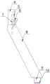
FIG. 1 is a front view of a support frame for hydraulic and hydroelectric engineering construction according to the present invention;
FIG. 2 is a structural view of the stand bar of the present invention;
FIG. 3 is a block diagram of the bottom plate of the present invention;
fig. 4 is a structural diagram of the supporting member of the present invention.
In the figure, a top plate 1; a support leg 2; a base plate 3; the upper embedded column 4; an adjustment groove 5; a support plate 6; a fixing rod 7; a connecting rod 8; a lower embedded column 9; an embedding groove 10; a slot 11; a bump 12; a rubber pad 13; a spherical groove 14; a support 15; a foot pad 16; a center block 17; a longitudinal support bar 18; a support plate 19; a transverse support bar 20.
Detailed Description
The technical solutions in the embodiments of the present invention will be described clearly and completely with reference to the accompanying drawings in the embodiments of the present invention, and it is obvious that the described embodiments are only some embodiments of the present invention, not all embodiments. Based on the embodiments in the present invention, all other embodiments obtained by a person skilled in the art without creative work belong to the protection scope of the present invention.
Referring to fig. 1-4, the present invention provides a technical solution: a support frame for hydraulic and hydroelectric engineering construction comprises: the supporting leg comprises a top plate 1, supporting legs 2 and a bottom plate 3, wherein the number of the supporting legs 2 is three, each supporting leg 2 comprises an upper embedded column 4, a connecting rod 8 and a lower embedded column 9, a through hole 21 is formed in the surface of the top plate 1, the upper embedded column 4 is connected with the through hole 21 in an embedded mode, a plurality of adjusting grooves 5 are formed in the side wall of the upper embedded column 4, a supporting plate 6 is connected to the side wall of the upper embedded column 4 in an embedded mode, fixing rods 7 are arranged on the left side and the bottom of the supporting plate 6, the fixing rods 7 are connected with the adjusting grooves 5 in an embedded mode, the upper embedded column and the lower embedded column are vertically arranged, the connecting rods 8 are obliquely arranged, the inclination angles of the adjusting grooves 5 and the fixing rods 7 are the same, two groups; slot 11 has been seted up at bottom plate 3 top surface middle part, and lower inlay post 9 and be connected with slot 11 inlays, and spherical groove 14 has been seted up to bottom plate 3's bottom surface, and spherical groove 14 interior level is fixed with support piece 15, and spherical groove 14's cross-section is the arch, possesses certain support strength.
Further improved, as shown in fig. 4: support piece 15 is whole netted, and support piece 15 includes center block 17, longitudinal support pole 18, backup pad 19 and horizontal bracing piece 20, and backup pad 19 adopts the steel sheet to enclose to close and form and be the hexagon structure, and backup pad 19 is equipped with three and size outside-in altogether and reduces in proper order, and 19 structural strength of hexagon backup pad are better.
Further improved, as shown in fig. 4: the number of the transverse supporting rods 20 is six, the transverse supporting rods 20 are connected with the central block 17, the six transverse supporting plates 19 are axially and equidistantly distributed by taking the central block 17 as a center, the other ends of the transverse supporting rods 20 are connected with the inner wall of the spherical groove 14, the transverse supporting rods 20 are connected with the supporting plates 19 in a welding mode, the transverse supporting rods 20 are connected with the centers of the side edges of the supporting plates 19, force is easily diffused when the force is applied, and a certain buffering effect is achieved.
Further improved, as shown in fig. 4: the vertical setting of longitudinal support pole 18 is in the junction of middle part backup pad 19 and horizontal bracing piece 20, and longitudinal support pole 18 extends and is connected with callus on the sole 16 to backup pad 19 below, and the callus on the sole 16 bottom surface is the level with bottom plate 3 bottom surface and aligns, and callus on the sole 16 is made for rubber materials, plays certain antiskid and cushioning effect.
Specifically, slot 11 bottom is provided with rubber pad 13, and rubber pad 13 top is provided with the lug 12 that a plurality of equidistance distributes, inlays the post 9 bottom surface down and has seted up a plurality of and inlay groove 10, and lug 12 is connected with inlaying groove 10, inlays down that post 9 inlays behind slot 11, and lug 12 can be inlayed to inlaying in the groove 10, improves the stability of connecting, and lug 12 is the trapezium structure and adopts rubber materials to make, possesses the cushioning effect simultaneously.
The utility model discloses when the installation, inlay post 9 and slot 11 earlier and be connected with the lower of stabilizer blade 2 and inlay, lug 12 is connected with inlaying groove 10, insert the dead lever 7 under the layer board 6 in the adjustment tank 5, then be connected roof 1 and stabilizer blade 2, inlay post 4 and insert through-hole 21 and can accomplish the installation on the messenger, need adjust the time of roof 1 height, take out roof 1 then adjust the position of layer board 6, install roof 1 again can, when a support frame receives the shake or the pressurized, support piece 15 through in the bottom plate 3, the callus on the sole 16 of lug 12 and bottom plays certain shock attenuation's effect of buffering, support piece 15 improves the structural strength of bottom plate 3.
The product protected by the scheme is put into practical production and application at present, and particularly has certain success in the application in the field of hydraulic and hydroelectric engineering, and obviously proves that the technical scheme of the product is beneficial, meets social requirements, and is suitable for batch production and popularization and use.
Finally, it should be noted that: although the present invention has been described in detail with reference to the foregoing embodiments, it will be apparent to those skilled in the art that modifications may be made to the embodiments described in the foregoing embodiments, or equivalents may be substituted for elements thereof. Any modification, equivalent replacement, or improvement made within the spirit and principle of the present invention should be included in the protection scope of the present invention.
Claims (5)
1. A support frame for hydraulic and hydroelectric engineering construction comprises: roof (1), stabilizer blade (2) and bottom plate (3), its characterized in that: the supporting legs (2) are provided with three supporting legs, each supporting leg (2) comprises an upper embedded column (4), a connecting rod (8) and a lower embedded column (9), a through hole (21) is formed in the surface of the top plate (1), the upper embedded columns (4) are connected with the through holes (21) in an embedded mode, a plurality of adjusting grooves (5) are formed in the side walls of the upper embedded columns (4), supporting plates (6) are connected to the side walls of the upper embedded columns (4) in an embedded mode, fixing rods (7) are arranged on the left sides and the bottoms of the supporting plates (6), and the fixing rods (7) are connected with the adjusting grooves (5) in an embedded mode;
slot (11) have been seted up in bottom plate (3) top surface middle part, inlay post (9) and inlay with slot (11) down and be connected, spherical groove (14) have been seted up to the bottom surface of bottom plate (3), level is fixed with support piece (15) in spherical groove (14).
2. The support frame for hydraulic and hydroelectric engineering construction according to claim 1, wherein: support piece (15) wholly are netted, and support piece (15) include center block (17), vertical bracing piece (18), backup pad (19) and horizontal bracing piece (20), backup pad (19) adopt the steel sheet to enclose to close and form and be the hexagon structure, backup pad (19) are equipped with three and size outside-in altogether and reduce in proper order.
3. The support frame for hydraulic and hydroelectric engineering construction according to claim 2, wherein: horizontal bracing piece (20) are provided with six altogether, and horizontal bracing piece (20) are connected with center block (17), and six horizontal bracing pieces (19) use center block (17) to distribute as central axial equidistance, the other end and spherical groove (14) inner wall connection of horizontal bracing piece (20), just horizontal bracing piece (20) and bracing piece (19) welded connection.
4. The support frame for hydraulic and hydroelectric engineering construction according to claim 2, wherein: the vertical setting of longitudinal support pole (18) is in the junction of middle part backup pad (19) and horizontal bracing piece (20), longitudinal support pole (18) extend and are connected with callus on the sole (16) to backup pad (19) below, callus on the sole (16) bottom surface is the level with bottom plate (3) bottom surface and aligns.
5. The support frame for hydraulic and hydroelectric engineering construction according to claim 1, wherein: the bottom of the slot (11) is provided with a rubber pad (13), the top of the rubber pad (13) is provided with a plurality of lugs (12) distributed at equal intervals, the bottom surface of the lower embedded column (9) is provided with a plurality of embedded grooves (10), and the lugs (12) are connected with the embedded grooves (10).
Priority Applications (1)
| Application Number | Priority Date | Filing Date | Title |
|---|---|---|---|
| CN201920851818.2U CN210164284U (en) | 2019-06-06 | 2019-06-06 | Support frame for hydraulic and hydroelectric engineering construction |
Applications Claiming Priority (1)
| Application Number | Priority Date | Filing Date | Title |
|---|---|---|---|
| CN201920851818.2U CN210164284U (en) | 2019-06-06 | 2019-06-06 | Support frame for hydraulic and hydroelectric engineering construction |
Publications (1)
| Publication Number | Publication Date |
|---|---|
| CN210164284U true CN210164284U (en) | 2020-03-20 |
Family
ID=70171407
Family Applications (1)
| Application Number | Title | Priority Date | Filing Date |
|---|---|---|---|
| CN201920851818.2U Expired - Fee Related CN210164284U (en) | 2019-06-06 | 2019-06-06 | Support frame for hydraulic and hydroelectric engineering construction |
Country Status (1)
| Country | Link |
|---|---|
| CN (1) | CN210164284U (en) |
-
2019
- 2019-06-06 CN CN201920851818.2U patent/CN210164284U/en not_active Expired - Fee Related
Similar Documents
| Publication | Publication Date | Title |
|---|---|---|
| CN110011598B (en) | Prestressed double-layer suspension cable photovoltaic bracket | |
| CN214884612U (en) | Office building outer wall steel structure design structure | |
| CN216741570U (en) | Shaft bottom syncline mining supporting device under coal mine | |
| CN208251623U (en) | A kind of concrete column form bracing system | |
| CN207160604U (en) | Architectural engineering assembled bearing | |
| CN204115558U (en) | The hanging supporting of a kind of cooling tower graticule mesh | |
| CN203049956U (en) | Folding stage ladder | |
| CN214315151U (en) | Angle-adjustable support frame matched with photovoltaic panel on side slope | |
| CN206243402U (en) | Floating on water photovoltaic bracket system sub-array units | |
| CN216240095U (en) | Protection machanism for hydraulic engineering | |
| CN214362885U (en) | Cast-in-situ lower cross beam support frame | |
| CN213952505U (en) | Steel structure supporting seat | |
| CN214656427U (en) | Bent pier T constructs interim anchor antidumping device | |
| CN204311359U (en) | A kind of steel pipe concrete arch rib bridge arch pin is installed and is used stiffness support | |
| CN205063498U (en) | Increase beam column | |
| CN209976062U (en) | Constructional engineering frame roof beam reinforcing apparatus | |
| CN209949014U (en) | Dead weight formula photovoltaic support | |
| CN210561745U (en) | Box girder reinforcing steel bar jig processing structure | |
| CN223305751U (en) | A tunnel vault support device for extremely high ground stress tunnel construction | |
| CN212330163U (en) | Bed-jig is used in production of hoist roof beam box | |
| CN213837428U (en) | Horizontal ladder for positioning building industrialization project conversion layer | |
| CN220035809U (en) | Waste stone slab modularized outer wall dry-hanging structure | |
| CN218264287U (en) | An adjustable assembled frame | |
| CN224106831U (en) | Cantilever support and climbing frame attachment integrated steel platform | |
| CN211873609U (en) | High-strength aluminum alloy railing |
Legal Events
| Date | Code | Title | Description |
|---|---|---|---|
| GR01 | Patent grant | ||
| GR01 | Patent grant | ||
| CF01 | Termination of patent right due to non-payment of annual fee | ||
| CF01 | Termination of patent right due to non-payment of annual fee |
Granted publication date: 20200320 Termination date: 20210606 |