CN210147486U - Five-axis machining equipment for blade - Google Patents
Five-axis machining equipment for blade Download PDFInfo
- Publication number
- CN210147486U CN210147486U CN201920921186.2U CN201920921186U CN210147486U CN 210147486 U CN210147486 U CN 210147486U CN 201920921186 U CN201920921186 U CN 201920921186U CN 210147486 U CN210147486 U CN 210147486U
- Authority
- CN
- China
- Prior art keywords
- sliding
- block
- blade
- horizontal
- driving device
- Prior art date
- Legal status (The legal status is an assumption and is not a legal conclusion. Google has not performed a legal analysis and makes no representation as to the accuracy of the status listed.)
- Expired - Fee Related
Links
Images


Abstract
The utility model relates to a five-axis blade machining device, which comprises a workbench, a first horizontal sliding component, a second horizontal sliding component, a longitudinal lifting component, a fixture rotating component, a horizontal rotating component and a blade fixture, wherein the first horizontal sliding component and the second horizontal sliding component are mutually perpendicular arranged on the workbench, the longitudinal lifting component is arranged on the first horizontal sliding component, the horizontal rotating component is arranged on the second horizontal sliding component, the fixture rotating component is arranged on the horizontal rotating component, the blade fixture is arranged on the fixture rotating component, and the longitudinal lifting component is provided with a machining device. And the stability and the positioning precision of clamping the blade workpiece can be improved through the blade fixture, and the quality of the blade is effectively improved.
Description
Technical Field
The utility model relates to a blade processing technology field indicates a blade five-axis machining equipment especially.
Background
At present, most of numerical control tools are processed manually, so that the processing efficiency is low, the labor cost is high, the processing quality is poor, and the processing requirement of high-precision workpieces cannot be met.
SUMMERY OF THE UTILITY MODEL
In order to solve the problem, the utility model provides an automatic change processing cutter, machining efficiency height, blade five-axis machining equipment that processingquality is good.
In order to achieve the above object, the utility model adopts the following technical scheme: the utility model provides a blade five-axis machining equipment, slides part, vertical lifting means, anchor clamps rotary part, horizontal rotation part and sword grain anchor clamps including workstation, first level, second level, first level slides part and second level and slides part mutually perpendicular and establish on the workstation, vertical lifting means establishes on first level slides the part, horizontal rotation part establishes on second level slides the part, anchor clamps rotary part establishes on horizontal rotation part, sword grain anchor clamps are installed on anchor clamps rotary part, be equipped with the processing device on vertical lifting means.
Preferably, the first horizontal sliding component comprises a first driving device, a first sliding rail, a first sliding block and an installation block, the first sliding rail is arranged on the workbench, the first sliding block is arranged on the first sliding rail in a sliding manner, the installation block is fixedly arranged on the first sliding block, and the first driving device is connected with the installation block.
Preferably, the second horizontal sliding component comprises a second driving device, a second sliding rail, a second sliding block and a mounting plate, the second sliding rail is arranged on the workbench, the second sliding block is arranged on the second sliding rail in a sliding mode, the mounting plate is fixedly arranged on the second sliding block, and the second driving device is connected with the mounting plate.
Preferably, the longitudinal lifting member includes a third driving device, a third slide rail, a third slider and a mounting seat, the third slide rail is arranged on the first horizontal sliding member, the third slider is slidably arranged on the third slide rail, the mounting seat is fixedly arranged on the third slider, and the third driving device is connected with the mounting seat.
Preferably, the horizontal rotation component comprises a fourth driving device, a bottom plate, a rotary table and a supporting plate, the bottom plate is arranged on the second horizontal sliding component, the rotary table rotates on the bottom plate for 180 degrees, the supporting plate is fixedly arranged on the rotary table, and the fourth driving device is connected with the rotary table.
Preferably, anchor clamps rotary part includes fixing base, fifth drive arrangement and drive disk assembly, the fixing base is fixed to be established on horizontal rotary part, drive disk assembly is rotatable to be worn to establish in the fixing base, drive disk assembly's one end is connected with fifth drive arrangement, drive disk assembly's the other end is equipped with changes the board, be equipped with the clamp splice on changing the board, sword grain anchor clamps are installed between two clamp splices.
Preferably, the tool granule clamp comprises a clamp base, a light pressing part, a heavy pressing part, a positioning part and a workpiece positioning block, wherein a pressing block is movably arranged in the clamp base, the workpiece positioning block is arranged at one end of the clamp base, the pressing block is movably contacted with the workpiece positioning block, the light pressing part, the heavy pressing part and the positioning part are respectively arranged in the clamp base, and the light pressing part and the heavy pressing part are respectively connected with the pressing block.
Preferably, the processing device comprises a main shaft and a grinding wheel, the main shaft is provided with a tool shank, and the grinding wheel is mounted on the tool shank.
Preferably, the tool shank is arrow-shaped, and a mounting column is arranged at the tip end of the tool shank.
Preferably, the grinding wheel is a flat grinding wheel or a bowl-shaped grinding wheel.
The beneficial effects of the utility model reside in that: the utility model discloses simple structure through the position of five-axis linkage adjustment processing device and sword grain anchor clamps, can carry out the automated processing of different angles to the blade of installing on sword grain anchor clamps and handle, can process the blade of complicated shape, reduces the cost of labor, improves machining efficiency, and can improve steadiness and the positioning accuracy to blade work piece clamping through sword grain anchor clamps, effectively improves the quality of blade.
Drawings
Fig. 1 is a perspective view of the present invention.
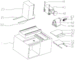
Fig. 2 is an explosion structure diagram of the present invention.
Fig. 3 is a perspective view of the insert holder.
Fig. 4 is an internal structural view of the insert holder.
Fig. 5 is an external structural view of the tool holder.
Description of reference numerals: 1. a work table; 2. a first horizontal sliding member; 21. a first slide rail; 22. a first slider; 23. mounting blocks; 3. a second horizontal sliding member; 31. a second slide rail; 32. a second slider; 33. mounting a plate; 4. a longitudinal lifting member; 41. a third slide rail; 42. a third slider; 44. a mounting seat; 5. a horizontal rotation member; 51. a base plate; 52. a turntable; 53. a support plate; 6. a clamp rotating member; 61. a fixed seat; 62. a transmission member; 63. rotating the plate; 7. a processing device; 8. a knife particle clamp; 81. a clamp base; 811. a groove; 812. a through hole; 813. a cover plate; 814. a set-top box; 82. lightly pressing the component; 821. lightly pressing the cylinder; 822. a cylinder joint; 823. a drive rack; 824. a transmission gear; 825. a cam; 83. a heavy pressing member; 831. a heavy-pressure cylinder; 832. a top block; 84. a positioning member; 841. positioning the air cylinder; 842. a top rod; 85. briquetting; 851. a rotating wheel; 86. a workpiece positioning block; 861. the drive shaft is positioned.
Detailed Description
Referring to fig. 1-2, the utility model discloses a blade five-axis machining equipment, including workstation 1, first horizontal sliding component 2, second horizontal sliding component 3, vertical lifting unit 4, anchor clamps rotary part 6, horizontal rotary part 5 and sword grain anchor clamps 8, first horizontal sliding component 2 and second horizontal sliding component 3 establish on workstation 1 and mutually perpendicular, vertical lifting unit 4 establishes on first horizontal sliding component 2, horizontal rotary part 5 establishes on second horizontal sliding component 3, anchor clamps rotary part 6 establishes on horizontal rotary part 5, sword grain anchor clamps 8 install on anchor clamps rotary part 6, be equipped with processing unit 7 on vertical lifting unit 4.
Preferably, the first horizontal sliding component 2 includes a first driving device, first sliding rails 21, first sliding blocks 22 and a mounting block 23, two first sliding rails 21 are arranged on the workbench 1, four first sliding blocks 22 are respectively arranged on the two first sliding rails 21 in a sliding manner, the mounting block 23 is fixedly arranged on the four first sliding blocks 22, and the first driving device (not shown in the figure) is connected with the mounting block 23.
Preferably, the second horizontal sliding component 3 includes a second driving device, second sliding rails 31, second sliding blocks 32 and a mounting plate 33, two of the second sliding rails 31 are disposed on the workbench 1 and are perpendicular to the first sliding rail 21, the four second sliding blocks 32 are respectively slidably disposed on the two second sliding rails 31, the mounting plate 33 is fixedly disposed on the second sliding blocks 32, and the second driving device (not shown in the figure) is connected to the mounting plate 33.
Preferably, the longitudinal lifting member 4 includes a third driving device, third sliding rails 41, third sliding blocks 42 and a mounting seat 44, two third sliding rails 41 are disposed on the side surface of the mounting block 23, four third sliding blocks 42 are respectively slidably disposed on the two third sliding rails 41, the mounting seat 44 is fixedly disposed on the third sliding blocks 42, and the third driving device (not shown in the figure) is connected to the mounting seat 44.
Preferably, the horizontal rotation member 5 includes a fourth driving device, a bottom plate 51, a turntable 52 and a support plate 53, the bottom plate 51 is disposed on the mounting plate 33, the turntable 52 rotates 180 ° on the bottom plate 51, the support plate 53 is fixedly disposed on the turntable 52, and the fourth driving device (not shown in the figure) is connected to the turntable 52.
Preferably, the fixture rotating part 6 includes a fixing seat 61, a fifth driving device and a transmission part 62, the fixing seat 61 is fixedly arranged on the supporting plate 53, the transmission part 62 is rotatably arranged in the fixing seat 61 in a penetrating manner, one end of the transmission part 62 is connected with the fifth driving device, the other end of the transmission part 62 is provided with a rotating plate 63, the rotating plate 63 is provided with clamping blocks, and the knife granule fixture 8 is arranged between the two clamping blocks.
Preferably, the processing device 7 includes a sixth driving device, a spindle and a grinding wheel, the spindle is disposed on the mounting seat 44 in a penetrating manner, the sixth driving device (not shown in the figure) is connected with the spindle, the spindle is provided with a tool shank, and the grinding wheel is connected with the tool shank.
Preferably, as can be seen from fig. 5, the tool shank is arrow-shaped, and the tip of the tool shank is provided with a mounting post.
Preferably, the tool shank is one of BT-30, BT-40 or BT-50.
Preferably, the grinding wheel is a flat grinding wheel or a bowl-shaped grinding wheel.
Referring to fig. 3-4, the insert holder 8 includes a holder base 81, a light pressing member 82, a heavy pressing member 83, a positioning member 84, and a workpiece positioning block 86, a through hole 812 is formed in the clamp base 81, a groove 811 is formed at the top end of the clamp base 81, a pressing block 85 is movably arranged in the groove 811, a cover plate 813 is arranged above the clamp base 81, a top box 814 is arranged above the cover plate 813, an accommodating groove is arranged in the top box 814, the top plate is arranged on the top box 814, the light pressing part 82 is arranged in the top box 814, the heavy pressing part 83 is arranged in the groove 811, the positioning member 84 is provided in the through hole 812, the workpiece positioning block 86 is provided at one end of the recess 811, the light-pressure component 82 and the heavy-pressure component 83 are respectively connected with a pressing block 85, the pressing block 85 is movably abutted against a workpiece positioning block 86, and the positioning component 84 is connected with the workpiece positioning block 86.
Preferably, a positioning pin penetrates through the pressing block 85, the pressing block 85 is movably arranged in the groove 811 through the positioning pin, one end of the pressing block 85 is provided with a rotating wheel 851, and the other end of the pressing block 85 is provided with a positioning column.
Preferably, the bottom end of the workpiece positioning block 86 is connected with a positioning transmission shaft 861, and the positioning transmission shaft 861 is vertically movably arranged in the fixture base 81.
Preferably, the light-pressure component 82 includes a light-pressure cylinder 821, a cylinder joint 822, a transmission rack 823, a transmission gear 824 and a cam 825, the light-pressure cylinder 821 is disposed on one side of the top box 814, the cylinder joint 822 is connected to a piston rod of the light-pressure cylinder 821, the transmission rack 823 is slidably disposed in the top box 814 and is fixedly connected to the cylinder joint 822, the transmission gear 824 is disposed on a rotating shaft, the rotating shaft is rotatably disposed on the cover plate 813 in a penetrating manner, the transmission gear 824 is engaged with the transmission rack 823, the cam 825 is disposed at a bottom end of the rotating shaft, the cam 825 abuts against the pressing block 85, the light-pressure cylinder 821 enables the transmission rack 823 to slide through the cylinder joint 822, the transmission rack 823 drives the transmission gear 824 to rotate, the cam 825 is rotated through the rotating shaft, the pressing block 85 is driven to rotate, and.
Preferably, the positioning part 84 includes a positioning cylinder 841 and a push rod 842, the positioning cylinder 841 is arranged on the side wall of the fixture base 81, the push rod 842 is connected with the positioning cylinder 841, the push rod 842 is arranged in the through hole 812 in a penetrating manner, one end of the push rod 842 is provided with a second inclined surface, the push rod 842 is abutted against a positioning transmission shaft 861 through the second inclined surface, the positioning cylinder 841 drives the push rod 842 to move, the push rod 842 drives the positioning transmission shaft 861 to move up and down through the second inclined surface, so that the position of the workpiece positioning block 86 is adjusted, and the workpiece corresponds to the positioning column of the pressing block 85.
Preferably, the heavy pressure component 83 includes a heavy pressure cylinder 831 and a top block 832, the heavy pressure cylinder 831 is disposed on a side wall of the fixture base 81, the top block 832 is connected with a piston rod of the heavy pressure cylinder 831, the top block 832 is provided with a first inclined surface, the first inclined surface abuts against the rotating wheel 851 so that the top block 832 is coupled with the pressing block 85, the heavy pressure cylinder 831 drives the top block 832 to move, the top block 832 drives the rotating wheel 851 to rotate through the first inclined surface, and the pressing block 85 presses the workpiece on the workpiece positioning block 86.
The working principle is as follows: clamping a cutter particle clamp 8 on a clamp rotating component 6, placing a cutter particle workpiece on a workpiece positioning block 86, positioning a pressing block 85 and the cutter particle workpiece through a light pressing component 82 and a positioning component 84, driving the pressing block 85 to tightly press the cutter particle workpiece on the workpiece positioning block 86 through a heavy pressing component, after the cutter particle workpiece is positioned and clamped, driving an installation block 23 to move in the X-axis direction through a first driving device, driving an installation plate 33 to move in the Y-axis direction through a second driving device and driving an installation seat 44 to lift in the Z-axis direction through a third driving device, so as to adjust the relative position of a processing device 7 and the cutter particle clamp 8; the fourth driving device drives the turntable 52180 to rotate for an angle to drive the cutter particle clamp 8 to horizontally rotate, the fifth driving device drives the transmission part 62 to rotate, and the transmission part 62 drives the cutter particle clamp 8360 to rotate for an angle to adjust the machining angle of the cutter particle workpiece; the processing device 7 works, and the positions and the angles of the processing device 7 and the knife grain workpiece are continuously adjusted through the first horizontal sliding component 2, the second horizontal sliding component 3, the longitudinal lifting component 4, the horizontal rotating component 5 and the clamp rotating component 6, so that different angles of the knife grain workpiece are processed.
The utility model discloses simple structure can process the blade and the sword grain of complicated shape, be applicable to processing carbide and ceramic sword grain field, can process the blade of turning tooth sword grain, high accuracy milling cutter piece, belt pulley blade, cutting off cutter or other usage, application scope is wide, the commonality is good, through five-axis linkage processing, effectively improve machining efficiency, reduce the cost of labor, it is tight to the location clamp of sword grain work piece through sword grain anchor clamps 8, improve the machining precision of work piece, promote the quality of sword grain.
The above embodiments are only for describing the preferred embodiments of the present invention, and are not intended to limit the scope of the present invention, and various modifications and improvements made by the technical solution of the present invention by those skilled in the art are all within the scope of the present invention as defined by the claims.
Claims (10)
1. The five-axis machining equipment for the blade is characterized in that: including workstation, first horizontal sliding component, second horizontal sliding component, vertical lifting unit, anchor clamps rotary part, horizontal rotation part and sword grain anchor clamps, first horizontal sliding component establishes on the workstation with second horizontal sliding component mutually perpendicular, vertical lifting unit establishes on first horizontal sliding component, horizontal rotation part establishes on second horizontal sliding component, anchor clamps rotary part establishes on horizontal rotation part, sword grain anchor clamps are installed on anchor clamps rotary part, be equipped with processing device on the vertical lifting unit.
2. The five-axis machining apparatus for a blade of claim 1, characterized in that: the first horizontal sliding component comprises a first driving device, a first sliding rail, a first sliding block and an installation block, the first sliding rail is arranged on the workbench, the first sliding block is arranged on the first sliding rail in a sliding mode, the installation block is fixedly arranged on the first sliding block, and the first driving device is connected with the installation block.
3. The five-axis machining apparatus for a blade of claim 1, characterized in that: the second horizontal sliding component comprises a second driving device, a second sliding rail, a second sliding block and a mounting plate, the second sliding rail is arranged on the workbench, the second sliding block is arranged on the second sliding rail in a sliding mode, the mounting plate is fixedly arranged on the second sliding block, and the second driving device is connected with the mounting plate.
4. The five-axis machining apparatus for a blade of claim 1, characterized in that: the longitudinal lifting component comprises a third driving device, a third sliding rail, a third sliding block and a mounting seat, the third sliding rail is arranged on the first horizontal sliding component, the third sliding block is arranged on the third sliding rail in a sliding mode, the mounting seat is fixedly arranged on the third sliding block, and the third driving device is connected with the mounting seat.
5. The five-axis machining apparatus for a blade of claim 1, characterized in that: the horizontal rotating part comprises a fourth driving device, a bottom plate, a rotary table and a supporting plate, the bottom plate is arranged on the second horizontal sliding part, the rotary table rotates for 180 degrees on the bottom plate, the supporting plate is fixedly arranged on the rotary table, and the fourth driving device is connected with the rotary table.
6. The five-axis machining apparatus for a blade of claim 1, characterized in that: the fixture rotating part comprises a fixing seat, a fifth driving device and a transmission part, the fixing seat is fixedly arranged on the horizontal rotating part, the transmission part is rotatably arranged in the fixing seat in a penetrating mode, one end of the transmission part is connected with the fifth driving device, the other end of the transmission part is provided with a rotating plate, a clamping block is arranged on the rotating plate, and the knife grain fixture is arranged between the two clamping blocks.
7. The five-axis machining apparatus for a blade of claim 1, characterized in that: the cutter granule clamp comprises a clamp base, a light pressing part, a heavy pressing part, a positioning part and a workpiece positioning block, wherein a pressing block is movably arranged in the clamp base, the workpiece positioning block is arranged at one end of the clamp base, the pressing block is movably contacted with the workpiece positioning block, the light pressing part, the heavy pressing part and the positioning part are respectively arranged in the clamp base, and the light pressing part and the heavy pressing part are respectively connected with the pressing block.
8. The five-axis machining apparatus for a blade of claim 1, characterized in that: the processing device comprises a main shaft and a grinding wheel, the main shaft is provided with a tool shank, and the grinding wheel is installed on the tool shank.
9. The five-axis machining apparatus for a blade of claim 8, wherein: the handle of a knife is arrow-shaped, and its pointed end is equipped with the erection column.
10. The five-axis machining apparatus for a blade of claim 8, wherein: the grinding wheel is a plane grinding wheel or a bowl-shaped grinding wheel.
Priority Applications (1)
| Application Number | Priority Date | Filing Date | Title |
|---|---|---|---|
| CN201920921186.2U CN210147486U (en) | 2019-06-19 | 2019-06-19 | Five-axis machining equipment for blade |
Applications Claiming Priority (1)
| Application Number | Priority Date | Filing Date | Title |
|---|---|---|---|
| CN201920921186.2U CN210147486U (en) | 2019-06-19 | 2019-06-19 | Five-axis machining equipment for blade |
Publications (1)
| Publication Number | Publication Date |
|---|---|
| CN210147486U true CN210147486U (en) | 2020-03-17 |
Family
ID=69763432
Family Applications (1)
| Application Number | Title | Priority Date | Filing Date |
|---|---|---|---|
| CN201920921186.2U Expired - Fee Related CN210147486U (en) | 2019-06-19 | 2019-06-19 | Five-axis machining equipment for blade |
Country Status (1)
| Country | Link |
|---|---|
| CN (1) | CN210147486U (en) |
-
2019
- 2019-06-19 CN CN201920921186.2U patent/CN210147486U/en not_active Expired - Fee Related
Similar Documents
| Publication | Publication Date | Title |
|---|---|---|
| CN211489708U (en) | Radial drill of high efficiency high accuracy | |
| CN108581542B (en) | Clamping tool for flat plate type parts | |
| CN211249228U (en) | High-positioning milling machine | |
| CN210147486U (en) | Five-axis machining equipment for blade | |
| CN213164235U (en) | Machine tool machining equipment fixed block limit structure | |
| CN201906995U (en) | Rotary worktable | |
| CN111015382B (en) | Negative chamfering grinding machine tool | |
| CN110666540B (en) | Rotary machining clamp assembly | |
| CN114799890A (en) | Turning and milling combined machining center | |
| CN218136528U (en) | Clamp for fixing in vertical machining center | |
| CN212496854U (en) | Vertical shaft circular truncated cone surface grinding machine | |
| CN220462943U (en) | Vertical lifting table milling machine | |
| CN213163604U (en) | Multi-station ultrasonic metal welding equipment | |
| CN219788274U (en) | Workpiece clamping device | |
| CN217913058U (en) | Workbench adjusting device for milling machine | |
| CN215393902U (en) | Four-axis anchor clamps of convenient debugging | |
| CN218017203U (en) | Bench drilling machine positioning device | |
| CN217413208U (en) | Clamp for machine tool | |
| CN215431712U (en) | Special machine tool for milling groove | |
| CN216577175U (en) | Opposite vertex fixture mechanism and machine tool | |
| CN220050924U (en) | Workbench assembly for vertical machining center | |
| CN213497841U (en) | Milling machine processing tool clamp | |
| CN219767415U (en) | Chamfering device for milling machine machining plate parts | |
| CN217799065U (en) | Numerical control drilling machine | |
| CN214640440U (en) | Numerical control machining center convenient to adjust and fix for machining special-shaped shell parts |
Legal Events
| Date | Code | Title | Description |
|---|---|---|---|
| GR01 | Patent grant | ||
| GR01 | Patent grant | ||
| CF01 | Termination of patent right due to non-payment of annual fee | ||
| CF01 | Termination of patent right due to non-payment of annual fee |
Granted publication date: 20200317 Termination date: 20210619 |