CN210134641U - Construction structures is pour to concrete link plate secondary under roof beam - Google Patents
Construction structures is pour to concrete link plate secondary under roof beam Download PDFInfo
- Publication number
- CN210134641U CN210134641U CN201920482399.XU CN201920482399U CN210134641U CN 210134641 U CN210134641 U CN 210134641U CN 201920482399 U CN201920482399 U CN 201920482399U CN 210134641 U CN210134641 U CN 210134641U
- Authority
- CN
- China
- Prior art keywords
- hanging plate
- link plate
- template
- reinforcing
- steel pipe
- Prior art date
- Legal status (The legal status is an assumption and is not a legal conclusion. Google has not performed a legal analysis and makes no representation as to the accuracy of the status listed.)
- Expired - Fee Related
Links
- 238000010276 construction Methods 0.000 title claims abstract description 20
- 230000003014 reinforcing effect Effects 0.000 claims abstract description 21
- 229910000831 Steel Inorganic materials 0.000 claims abstract description 14
- 239000010959 steel Substances 0.000 claims abstract description 14
- 229910001294 Reinforcing steel Inorganic materials 0.000 claims abstract description 7
- 238000009415 formwork Methods 0.000 abstract description 6
- 230000001737 promoting effect Effects 0.000 abstract 1
- 230000005540 biological transmission Effects 0.000 description 1
- 230000000694 effects Effects 0.000 description 1
- 238000007689 inspection Methods 0.000 description 1
- 239000007788 liquid Substances 0.000 description 1
- 238000000034 method Methods 0.000 description 1
- 210000003205 muscle Anatomy 0.000 description 1
- 239000013049 sediment Substances 0.000 description 1
Images

Landscapes
- Conveying And Assembling Of Building Elements In Situ (AREA)
Abstract
A secondary pouring construction structure for a concrete hanging plate under a beam relates to the technical field of constructional engineering. The reinforcing structure comprises a rectangular hole reserved on a floor slab at the position of a beam lower hanging plate and a reinforcing mechanism used for reinforcing the beam lower hanging plate; the reinforcing mechanism is including setting up the template of connecting between the link plate under rectangle hole and the roof beam, connecting in the outside reinforcement steel pipe of template, the template is including setting up the link plate exterior sheathing of connecting in the link plate periphery under the roof beam and connecting in the diagonal formwork between link plate exterior sheathing and rectangle hole, consolidate the steel pipe and set up and connect in link plate exterior sheathing periphery, the cross section of horizontal vertical steel pipe passes through the fastener and consolidates the connection, is located and consolidates through the split bolt between two vertical steel pipes of link plate exterior sheathing. The utility model discloses link plate construction quality under can promoting saves the secondary and pours the time, practices thrift the cost, avoids the later stage because of pouring the quality hidden danger that the untight picks chisel repair of vibration brought, also improves engineering economic benefits simultaneously, convenient construction.
Description
Technical Field
The utility model relates to a building engineering technical field, concretely relates to construction structures is pour to concrete link plate secondary under roof beam.
Background
In the building engineering, the first floor position of public building usually sets up concrete link plate under the roof beam, and the link plate effect is to replace the lintel, generally lies in public building first floor, two layers position, exists the interval between exterior window and the concrete structure roof beam, and general door and window size overlength is unsuitable to install the lintel, and the link plate is built with floor beam slab inconvenient pouring simultaneously in the earlier stage construction under the scene, reserves reinforcing bar or later stage bar planting, and the concrete link plate under the secondary pouring roof beam, and the process is generally for setting up the scaffold frame, prop up one side template, tie up the reinforcing bar, prop up another side template, concreting. From the whole construction condition, its comprehensive quality is not ideal, through the entity quality inspection after the form removal, finds that leaks thick liquid, not closely knit, exposes the muscle, presss from both sides the sediment etc. in the pouring time, the board takes artifical little transmission to pour into the concrete under the roof beam, and it is longer to consume time, and it is inconvenient to stand on the scaffold frame to construct under the beam slab.
SUMMERY OF THE UTILITY MODEL
In order to solve the problem, the utility model provides a construction structures is pour to concrete link plate secondary under roof beam can promote down link plate construction quality, saves the secondary and pours the time, practices thrift the cost, avoids later stage pick chisel to repair the quality hidden danger that brings, also improves engineering economic benefits simultaneously, convenient construction.
In order to achieve the above purpose, the utility model adopts the following technical scheme: the utility model provides a construction structures is pour to concrete link plate secondary under roof beam which characterized in that: the reinforcing structure comprises a rectangular hole reserved on a floor slab at the position of a beam lower hanging plate and a reinforcing mechanism used for reinforcing the beam lower hanging plate; the reinforcing mechanism is including setting up the template of connecting between the link plate under rectangle hole and the roof beam, connecting in the outside reinforcement steel pipe of template, the template is including setting up the link plate exterior sheathing of connecting in the link plate periphery under the roof beam and connecting in the diagonal formwork between link plate exterior sheathing and rectangle hole, consolidate the steel pipe and set up and connect in link plate exterior sheathing periphery, the cross section of horizontal vertical steel pipe passes through the fastener and consolidates the connection, is located and consolidates through the split bolt between two vertical steel pipes of link plate exterior sheathing.
The number of the rectangular holes is 2-3, the hole spacing is 3m, and the size is 300 x 300 mm.
The hanging plate outer formwork is connected with the reinforced steel pipe through the reinforcing blocks.
The utility model discloses take the upper portion floor position of concrete link plate under the roof beam to reserve the secondary and pour the hole, directly pour concrete placement's a structure from upper portion, can promote down link plate construction quality, save the secondary and pour the time, practice thrift the cost, avoid the later stage because of pour the quality hidden danger that the untight picks chisel repair of vibration brought, also improve engineering economic benefits simultaneously, convenient construction.
Drawings
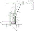
Fig. 1 is a schematic view of the overall structure of the present invention;
fig. 2 is a schematic structural view of the template of the present invention;
in the figure: 1-rectangular hole, 2-hanging plate under beam, 3-template, 3-1-hanging plate external template, 3-2-inclined template, 4-reinforced steel pipe, 5-fastener, 6-split bolt, 7-reinforcing block and 8-vibrating rod.
Detailed Description
The present invention will be further described with reference to the accompanying drawings and specific embodiments, but the present invention is not limited to the specific embodiments.
Examples
The secondary pouring construction structure for the concrete hanging plate under the beam shown in fig. 1 comprises a rectangular hole 1 reserved on a floor slab at the position of the concrete hanging plate under the beam 2 and a reinforcing mechanism used for reinforcing the concrete hanging plate under the beam 2; the reinforcing mechanism comprises a template 3 connected between a rectangular hole and a beam lower hanging plate 2 and a reinforcing steel pipe 4 connected to the outside of the template 3, as shown in figure 2, the template 3 comprises a hanging plate outer template 3-1 connected to the periphery of the beam lower hanging plate 2 and an inclined template 3-2 connected between the hanging plate outer template 3-1 and the rectangular hole 1, the reinforcing steel pipe 4 is connected to the periphery of the hanging plate outer template 3-1 in an erected mode, the cross part of the transverse and vertical steel pipes is connected in a reinforced mode through a fastener 5, and the two vertical steel pipes located between the hanging plate outer templates 3-1 are reinforced through a split bolt 6. The hanging plate outer template 3-1 is connected with the reinforced steel pipe 4 through a reinforcing block 7.
The number of the rectangular holes 1 is determined to be 2-3 according to the length of the lower hanging plate, the hole spacing is 3m, and the size is 300 x 300 mm.
The utility model discloses the use: a constructor stands on an upper construction operation layer of the hanging plate 2 under the beam, concrete is poured from top to bottom, a rectangular hole 1 is formed in a concrete inlet, a vibrating rod 8 extends into a hanging plate reinforcing steel bar in a hanging plate outer formwork 3-1 along an inclined formwork 3-2 from the rectangular hole 1 to vibrate, secondary pouring construction of the hanging plate under the beam is completed, and then hanging formwork plugging is conducted on the rectangular hole 1.
Claims (3)
1. The utility model provides a construction structures is pour to concrete link plate secondary under roof beam which characterized in that: the reinforcing structure comprises a rectangular hole (1) reserved on a floor slab at the position of a beam lower hanging plate (2) and a reinforcing mechanism used for reinforcing the beam lower hanging plate (2); the reinforcing mechanism comprises a template (3) connected between a rectangular hole (1) and a beam lower hanging plate (2) and a reinforcing steel pipe (4) connected to the outside of the template (3), wherein the template (3) comprises a hanging plate outer template (3-1) connected to the periphery of the beam lower hanging plate (2) and an inclined template (3-2) connected between the hanging plate outer template (3-1) and the rectangular hole (1), the reinforcing steel pipe (4) is connected to the periphery of the hanging plate outer template (3-1), the cross position of the transverse and vertical steel pipe is connected in a reinforcing mode through a fastener (5), and the two vertical steel pipes located between the hanging plate outer template (3-1) are reinforced through split bolts (6).
2. The secondary pouring construction structure for the concrete hanging plate under the beam according to claim 1, is characterized in that: the number of the rectangular holes (1) is 2-3, the hole spacing is 3m, and the size is 300 x 300 mm.
3. The secondary pouring construction structure for the concrete hanging plate under the beam according to claim 1, is characterized in that: the hanging plate outer template (3-1) is connected with the reinforced steel pipe (4) through a reinforcing block (7).
Priority Applications (1)
| Application Number | Priority Date | Filing Date | Title |
|---|---|---|---|
| CN201920482399.XU CN210134641U (en) | 2019-04-11 | 2019-04-11 | Construction structures is pour to concrete link plate secondary under roof beam |
Applications Claiming Priority (1)
| Application Number | Priority Date | Filing Date | Title |
|---|---|---|---|
| CN201920482399.XU CN210134641U (en) | 2019-04-11 | 2019-04-11 | Construction structures is pour to concrete link plate secondary under roof beam |
Publications (1)
| Publication Number | Publication Date |
|---|---|
| CN210134641U true CN210134641U (en) | 2020-03-10 |
Family
ID=69703030
Family Applications (1)
| Application Number | Title | Priority Date | Filing Date |
|---|---|---|---|
| CN201920482399.XU Expired - Fee Related CN210134641U (en) | 2019-04-11 | 2019-04-11 | Construction structures is pour to concrete link plate secondary under roof beam |
Country Status (1)
| Country | Link |
|---|---|
| CN (1) | CN210134641U (en) |
Cited By (3)
| Publication number | Priority date | Publication date | Assignee | Title |
|---|---|---|---|---|
| CN116657898A (en) * | 2023-07-24 | 2023-08-29 | 山西三建集团建设工程有限公司 | Integral cast-in-situ construction method for beam plate and beam bottom L-shaped hanging plate |
| CN116892289A (en) * | 2023-07-24 | 2023-10-17 | 山西三建集团建设工程有限公司 | Formwork support system for integral casting of beam plate and L-shaped hanging plate at the bottom of the beam |
| CN118346050A (en) * | 2024-04-08 | 2024-07-16 | 中国五冶集团有限公司 | A secondary construction method for hanging slabs under concrete beams |
-
2019
- 2019-04-11 CN CN201920482399.XU patent/CN210134641U/en not_active Expired - Fee Related
Cited By (3)
| Publication number | Priority date | Publication date | Assignee | Title |
|---|---|---|---|---|
| CN116657898A (en) * | 2023-07-24 | 2023-08-29 | 山西三建集团建设工程有限公司 | Integral cast-in-situ construction method for beam plate and beam bottom L-shaped hanging plate |
| CN116892289A (en) * | 2023-07-24 | 2023-10-17 | 山西三建集团建设工程有限公司 | Formwork support system for integral casting of beam plate and L-shaped hanging plate at the bottom of the beam |
| CN118346050A (en) * | 2024-04-08 | 2024-07-16 | 中国五冶集团有限公司 | A secondary construction method for hanging slabs under concrete beams |
Similar Documents
| Publication | Publication Date | Title |
|---|---|---|
| CN210439720U (en) | A concrete beam side enlarged section reinforcement structure | |
| CN110306774B (en) | Method and device for installing socket type cantilever scaffold | |
| CN108149819B (en) | Integrated superposed outer wall of building bottom reinforcing area and production and construction method thereof | |
| CN106401207A (en) | Superimposed connection structure for additionally arranging column foundation on existing building and construction method of superimposed connection structure | |
| CN107013033A (en) | A kind of concrete side wall formwork for placing and its construction method | |
| CN115748961A (en) | Improved Steel Tube Constrained Precast Concrete Column Connection Structure and Construction Method | |
| CN111101715A (en) | Concrete windowsill coping combined construction method and structure | |
| CN2893055Y (en) | Super high wall body three-section form | |
| CN109252879A (en) | A kind of vcehicular tunnel gutter liner tool-typed formwork and construction method | |
| CN206071096U (en) | The underpinning device of load bearing wall in brick mix structure | |
| CN105019645B (en) | Fetch earth in contrary sequence method and the template system and construction method of xoncrete structure are built at mouth | |
| CN208534081U (en) | A kind of reconstruction structure of old building constructional column | |
| CN108625531A (en) | A kind of construction method pouring constructional column concrete non-dismantling formwork | |
| CN207647033U (en) | A kind of precast reinforced basket structure | |
| CN211850804U (en) | Shear force wall settlement joint steel wood combines template to prop up establishes device | |
| CN220598069U (en) | Integrated support system for cast-in-place formwork for concrete drainage ditches | |
| CN220451424U (en) | Template supporting system for integrally pouring beam plate and beam bottom L-shaped hanging plate | |
| CN206319404U (en) | A kind of building precast exterior sheathing | |
| CN215594892U (en) | High-rise transformation elevator shaft sealing plate formwork | |
| CN215052265U (en) | Reinforced concrete thin wall body reinforced structure | |
| CN112575812B (en) | Inner support conversion system applied to demolition and transformation project and construction method thereof | |
| CN116623986A (en) | Large-span space non-coplanar frame column pulling construction method | |
| CN212224611U (en) | Shear force wall pouring template reinforcing apparatus | |
| CN108930406A (en) | Construction method for large-formwork narrow-space wall based on integral assembly | |
| CN211369523U (en) | Template system of expansion joint shear force wall |
Legal Events
| Date | Code | Title | Description |
|---|---|---|---|
| GR01 | Patent grant | ||
| GR01 | Patent grant | ||
| CF01 | Termination of patent right due to non-payment of annual fee |
Granted publication date: 20200310 |
|
| CF01 | Termination of patent right due to non-payment of annual fee |