CN210125194U - Direct drinking water purifier front water treatment device - Google Patents
Direct drinking water purifier front water treatment device Download PDFInfo
- Publication number
- CN210125194U CN210125194U CN201920419428.8U CN201920419428U CN210125194U CN 210125194 U CN210125194 U CN 210125194U CN 201920419428 U CN201920419428 U CN 201920419428U CN 210125194 U CN210125194 U CN 210125194U
- Authority
- CN
- China
- Prior art keywords
- water
- filter
- water pump
- housing
- storage device
- Prior art date
- Legal status (The legal status is an assumption and is not a legal conclusion. Google has not performed a legal analysis and makes no representation as to the accuracy of the status listed.)
- Expired - Fee Related
Links
Images






Landscapes
- Water Treatment By Sorption (AREA)
Abstract
本实用新型提供一种直饮水净水车前置水处理装置,用于原水的前处理,包括前置过滤器,前置过滤器包括:过滤器外壳,在过滤器外壳的壳壁上分别设置有过滤进水结构和过滤出水孔;水泵,水泵设置在过滤器外壳的内部;过滤结构,过滤结构设置在过滤器外壳的内壁和水泵之间的空间中;在水泵的作用下,水通过过滤进水结构进入到前置过滤器的内部进行过滤,过滤后的水通过过滤出水孔输送出去。本实用新型由于采用了前置过滤器,前置过滤器不仅具有初步过滤的功能,还具有增压功能,可以将过滤后的水输送到更远的地方,相对现有技术,其结构设计更加合理,具有使用方便、设计合理、过滤效果好和增加水压等优点。

The utility model provides a pre-water treatment device for a direct drinking water purifying vehicle, which is used for the pre-treatment of raw water and comprises a pre-filter. The pre-filter comprises: a filter casing, which are respectively arranged on the casing wall of the filter casing. There is a filter inlet structure and a filter outlet hole; the water pump, the water pump is arranged inside the filter housing; the filter structure, the filter structure is arranged in the space between the inner wall of the filter housing and the water pump; under the action of the water pump, the water passes through the filter The water inlet structure enters the interior of the pre-filter for filtration, and the filtered water is transported out through the filtration outlet hole. Because the utility model adopts a pre-filter, the pre-filter not only has the function of preliminary filtering, but also has the function of pressurization, which can transport the filtered water to a farther place. Compared with the prior art, its structural design is more efficient. Reasonable, has the advantages of convenient use, reasonable design, good filtering effect and increased water pressure.
Description
技术领域technical field
本实用新型涉及原水的前置处理技术领域,尤其是涉及一种直饮水净水车前置水处理装置。The utility model relates to the technical field of pretreatment of raw water, in particular to a pretreatment device of a direct drinking water purifier.
背景技术Background technique
随着社会的不断发展,水污染日益加剧已成为事实,很多水源受污浊,其色度严重超标。而农村有很多地方使用雨水、窖水、湖泊以及水库等原水作为饮用水,原水中存在杂质,对身体健康存在安全隐患,在对水进行深度处理前,需要对原水进行前置处理,也就是说,原水的前置处理是对水进行净化处理前必须的设备。而现有技术中,使用的水处理前置过滤装置因其结构设计不合理,净化效果不理想。With the continuous development of society, it has become a fact that water pollution is increasing day by day. Many water sources are polluted and their chromaticity is seriously exceeding the standard. In many places in rural areas, raw water such as rainwater, cellar water, lakes and reservoirs is used as drinking water. There are impurities in the raw water, which poses a safety hazard to health. Before the advanced treatment of the water, the raw water needs to be pre-treated, that is, It is said that the pretreatment of raw water is a necessary equipment before the water purification treatment. However, in the prior art, the used pre-filtering device for water treatment is unreasonable in structure design, and the purification effect is unsatisfactory.
实用新型内容Utility model content
为了克服上述问题,本实用新型提供一种结构设计合理和净化效果好的直饮水净水车前置水处理装置。In order to overcome the above problems, the present utility model provides a front water treatment device for a direct drinking water purifier with reasonable structural design and good purification effect.
本实用新型的技术方案是:提供一种直饮水净水车前置水处理装置,用于原水的前处理,包括前置过滤器,所述前置过滤器包括:The technical scheme of the present utility model is to provide a pre-water treatment device for a direct drinking water purifying vehicle, which is used for the pre-treatment of raw water, and includes a pre-filter, and the pre-filter includes:
过滤器外壳,在所述过滤器外壳的壳壁上分别设置有过滤进水结构和过滤出水孔;a filter housing, a filter water inlet structure and a filter water outlet hole are respectively provided on the shell wall of the filter housing;
水泵,所述水泵设置在所述过滤器外壳的内部;a water pump, which is arranged inside the filter housing;
过滤结构,所述过滤结构设置在所述过滤器外壳的内壁和所述水泵之间的空间中;a filter structure, the filter structure is arranged in the space between the inner wall of the filter housing and the water pump;
在所述水泵的作用下,水通过所述过滤进水结构进入到所述前置过滤器的内部进行过滤,过滤后的水通过所述过滤出水孔输送出去。Under the action of the water pump, the water enters the interior of the pre-filter through the filtering water inlet structure for filtering, and the filtered water is transported out through the filtering water outlet.
作为对本实用新型的改进,还包括过滤出水管,所述过滤出水管的两端分别与所述水泵的出水口和所述过滤出水孔连通。As an improvement to the present utility model, a filter outlet pipe is also included, and the two ends of the filter outlet pipe are respectively communicated with the water outlet of the water pump and the filter outlet hole.
作为对本实用新型的改进,所述过滤器外壳包括外壳盖和至少一端开口的外壳体,所述外壳盖套设在所述外壳体的开口端上,所述过滤出水孔设置在所述外壳体的侧壁、所述外壳盖或所述外壳体的另一端上。As an improvement to the present invention, the filter housing includes a housing cover and an outer housing with at least one end open, the housing cover is sleeved on the open end of the outer housing, and the filtered water outlet hole is provided on the outer housing on the side wall, the housing cover or the other end of the housing.
作为对本实用新型的改进,还包括水泵固定架,所述水泵固定架设置在所述过滤器外壳的内部并形成固定腔室,所述固定腔室的一端为开口端,所述水泵通过所述固定腔室的开口端安装在所述固定腔室中,或者从所述固定腔室中移除。As an improvement to the present invention, it also includes a water pump fixing frame, the water pump fixing frame is arranged inside the filter housing and forms a fixing chamber, one end of the fixing chamber is an open end, and the water pump passes through the The open end of the fixation chamber is installed in or removed from the fixation chamber.
作为对本实用新型的改进,所述过滤器外壳的中轴位于所述固定腔室的内部或者外部。As an improvement to the present invention, the central axis of the filter housing is located inside or outside the fixed chamber.
作为对本实用新型的改进,所述水泵固定架的另一端与所述过滤器外壳的另一端内壁连接,所述水泵固定架的一端位于所述过滤器外壳的一端中,或所述水泵固定架的一端凸伸出所述过滤器外壳的一端。As an improvement to the present invention, the other end of the water pump fixing frame is connected to the inner wall of the other end of the filter housing, and one end of the water pump fixing frame is located in one end of the filter housing, or the water pump fixing frame One end protrudes out of one end of the filter housing.
作为对本实用新型的改进,还包括凸起结构,所述凸起结构设置在所述过滤器外壳的外壁上,并且所述凸起结构靠近所述过滤出水孔。As an improvement to the present invention, a raised structure is also included, the raised structure is arranged on the outer wall of the filter housing, and the raised structure is close to the filtered water outlet hole.
作为对本实用新型的改进,还包括储水装置,所述前置过滤器设置在所述储水装置的内部。As an improvement to the present invention, a water storage device is also included, and the pre-filter is arranged inside the water storage device.
作为对本实用新型的改进,在所述储水装置的一端开口,在所述储水装置的开口端上设置有储水盖,原水进水孔设置在所述储水装置的侧壁上,出水孔设置在所述储水装置的侧壁或所述储水盖上,所述过滤出水孔通过连接管与所述出水孔连通。As an improvement to the present invention, one end of the water storage device is opened, a water storage cover is arranged on the open end of the water storage device, and the raw water inlet hole is arranged on the side wall of the water storage device, and the water outlet The hole is arranged on the side wall of the water storage device or the water storage cover, and the filtered water outlet hole is communicated with the water outlet hole through a connecting pipe.
作为对本实用新型的改进,还包括PLC控制器,及分别与所述PLC控制器电性连接的第一电磁控制阀、低液位传感器、工作液位传感器和高液位传感器,所述第一电磁控制阀设置在与所述原水进水孔连通的原水进水路径上,所述低液位传感器、所述工作液位传感器和所述高液位传感器按照从低到高的顺序依序设置所述储水装置的内壁上,所述低液位传感器位于所述前置过滤器的上方。As an improvement to the present invention, it also includes a PLC controller, and a first electromagnetic control valve, a low liquid level sensor, a working liquid level sensor and a high liquid level sensor electrically connected to the PLC controller, respectively. The electromagnetic control valve is arranged on the raw water inlet path communicating with the raw water inlet hole, and the low liquid level sensor, the working liquid level sensor and the high liquid level sensor are arranged in order from low to high On the inner wall of the water storage device, the low liquid level sensor is located above the pre-filter.
本实用新型由于采用了前置过滤器,在前置过滤器中设置有过滤结构和水泵,在水泵的作用下,水通过过滤进水结构进入到前置过滤器的内部进行过滤,过滤后的水通过过滤出水孔输送出去,也就是说,前置过滤器不仅具有初步过滤的功能,还具有增压功能,可以将过滤后的水输送到更远的地方,相对现有技术,其结构设计更加合理,具有使用方便、设计合理、过滤效果好和增加水压等优点。Because the utility model adopts a pre-filter, a filtering structure and a water pump are arranged in the pre-filter. Under the action of the water pump, the water enters the interior of the pre-filter through the filtering water inlet structure for filtering. The water is transported out through the filtered water outlet, that is to say, the pre-filter not only has the function of preliminary filtering, but also has the function of supercharging, which can transport the filtered water to a farther place. Compared with the existing technology, its structural design It is more reasonable and has the advantages of convenient use, reasonable design, good filtering effect and increased water pressure.
附图说明Description of drawings
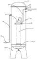
图1是本实用新型的一种实施例的局部透视结构示意图。FIG. 1 is a partial perspective structural schematic diagram of an embodiment of the present invention.
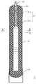
图2是图1中前置过滤器的一种实施例的平面结构示意图。FIG. 2 is a schematic plan view of an embodiment of the pre-filter in FIG. 1 .
图3是图2的剖视示意图。FIG. 3 is a schematic cross-sectional view of FIG. 2 .
图4是图2的A-A向剖视示意图。FIG. 4 is a schematic cross-sectional view taken along the line A-A in FIG. 2 .
图5是本实用新型的另一种实施例的局部透视结构示意图。FIG. 5 is a partial perspective structural schematic diagram of another embodiment of the present invention.
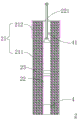
图6是本实用新型中前置过滤器的第三种实施例的剖视示意图。6 is a schematic cross-sectional view of the third embodiment of the pre-filter in the present invention.
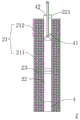
图7是本实用新型中前置过滤器的第四种实施例的剖视示意图。7 is a schematic cross-sectional view of the fourth embodiment of the pre-filter in the present invention.
图8是本实用新型中前置过滤器的第五种实施例的剖视示意图。8 is a schematic cross-sectional view of the fifth embodiment of the pre-filter in the present invention.
图9是本实用新型中前置过滤器的第六种实施例的剖视示意图。9 is a schematic cross-sectional view of the sixth embodiment of the pre-filter in the present invention.
图10是本实用新型中前置过滤器的第七种实施例的剖视示意图。10 is a schematic cross-sectional view of the seventh embodiment of the pre-filter in the present invention.
图11是本实用新型中前置过滤器的第八种实施例的剖视示意图。11 is a schematic cross-sectional view of the eighth embodiment of the pre-filter in the present invention.
图12是本实用新型中前置过滤器的第九种实施例的剖视示意图。12 is a schematic cross-sectional view of the ninth embodiment of the pre-filter in the present invention.
其中:1、储水装置;11、储水盖;12、出水孔;13、连接管;14、储水底座;15、排污阀;2、前置过滤器;21、过滤器外壳;211、外壳体;212、外壳盖;22、水泵;221、过滤出水管;23、过滤结构;25、过滤出水孔;26、凸起结构;27、过滤底座;28、外层;29、无纺布套筒;30、内层;31、第一电磁控制阀;32、低液位传感器;33、工作液位传感器; 34、高液位传感器;35、原水进水路径;4、水泵固定架;41、固定腔室;42、密封盖;43、水泵网板。Among them: 1, water storage device; 11, water storage cover; 12, water outlet; 13, connecting pipe; 14, water storage base; 15, drain valve; 2, pre-filter; 21, filter shell; 211, outer shell; 212, shell cover; 22, water pump; 221, filter outlet pipe; 23, filter structure; 25, filter outlet hole; 26, raised structure; 27, filter base; 28, outer layer; 29, non-woven fabric Sleeve; 30, inner layer; 31, first electromagnetic control valve; 32, low liquid level sensor; 33, working liquid level sensor; 34, high liquid level sensor; 35, raw water inlet path; 4, water pump fixing frame; 41. Fixed chamber; 42. Sealing cover; 43. Water pump mesh plate.
具体实施方式Detailed ways
在本实用新型的描述中,需要理解的是,术语中“中心”、“上”、“下”、“前”、“后”、“左”、“右”等指示的方位或位置关系为基于附图所示的方位或位置关系,仅是为了便于描述本实用新型和简化描述,而不是指示或暗示所指的装置或组件必须具有特定的方位、以特定的方位构造和操作,因此不能理解为对本实用新型的限制。此外,术语“第一”、“第二”仅用于描述目的,而不能理解为指示或暗示相对重要性。In the description of the present invention, it should be understood that the orientation or positional relationship indicated by "center", "upper", "lower", "front", "rear", "left" and "right" in the terms is Based on the orientation or positional relationship shown in the drawings, it is only for the convenience of describing the present invention and simplifying the description, rather than indicating or implying that the device or component referred to must have a specific orientation, be constructed and operated in a specific orientation, and therefore cannot It is understood as a limitation of the present invention. Furthermore, the terms "first" and "second" are used for descriptive purposes only and should not be construed to indicate or imply relative importance.
在本实用新型的描述中,需要说明的是,除非另有明确的规定和限定,术语“安装”、“连接”、“相连”应做广义理解,例如,可以是固定连接,也可以是拆卸连接,或一体地连接;可以是机械连接,也可以是电连接;可以是直接相连,也可以是通过中间媒介间接相连,可以是两个组件内部的连通。对于本领域的普通技术人员而言,可以具体情况理解上述术语在本实用新型的具体含义。In the description of the present invention, it should be noted that, unless otherwise expressly specified and limited, the terms "installation", "connection" and "connection" should be understood in a broad sense, for example, it may be a fixed connection or a disassembly Connection, or integral connection; it can be mechanical connection or electrical connection; it can be direct connection or indirect connection through an intermediate medium, and it can be internal communication between two components. For those of ordinary skill in the art, the specific meanings of the above terms in the present invention can be understood in specific situations.
请参见图1至图4,图1所揭示的是直饮水净水车前置水处理装置的一种实施例,图2所揭示的是直饮水净水车前置水处理装置中前置过滤器的一种实施例,图3和图4是图2中所示实施例的剖视示意图。Please refer to FIG. 1 to FIG. 4. FIG. 1 shows an embodiment of the front water treatment device of the direct drinking water purifier, and FIG. 2 shows the pre-filter in the front water treatment device of the direct drinking water purifier. Figure 3 and Figure 4 are schematic cross-sectional views of the embodiment shown in Figure 2.
所述直饮水净水车前置水处理装置包括前置过滤器2。所述前置水处理装置用于原水的前处理,即主要解决城市、集团、社区等集中式供水净化方案的原水前处理,其水源可以为城市自来水管网。当所述前置过滤器2单独使用时,原水可为地表水或地下水(地表水Ⅰ至Ⅲ类,地下水Ⅰ至Ⅳ类)。所述前置水处理装置可以作为直饮水深度处理的前置处理,直饮水深度处理包括超滤、纳滤和反渗透处理。The front water treatment device of the direct drinking water purification vehicle includes a pre-filter 2 . The pre-water treatment device is used for the pre-treatment of raw water, that is, the pre-treatment of raw water mainly solves the centralized water supply purification scheme of cities, groups, communities, etc., and the water source can be the urban tap water pipe network. When the pre-filter 2 is used alone, the raw water can be surface water or groundwater (surface water class I to III, groundwater class I to IV). The pretreatment device can be used as a pretreatment for the advanced treatment of direct drinking water, and the advanced treatment of direct drinking water includes ultrafiltration, nanofiltration and reverse osmosis treatment.
本实施例中,所述前置过滤器2包括过滤器外壳21、水泵22和过滤结构23(请参见图2和图3),所述前置过滤器2除了对原水进行初步过滤,还具有增压功能。所述前置过滤器2可以单独使用,所述前置过滤器2还可以配合储水装置1使用。In this embodiment, the pre-filter 2 includes a
所述过滤器外壳21可以采用金属材料制成,也可以采用PVC材料制成。所述过滤器外壳21包括外壳体211和外壳盖212,所述外壳体211的两端贯通,两个所述外壳盖212分别套设在所述过滤器外壳21的两端上。在所述过滤器外壳21的壳壁上分别设置有过滤进水结构和过滤出水孔25,即所述过滤进水结构设置在所述外壳体211的侧壁上或/和至少一个所述外壳盖212上,所述过滤出水孔25设置在至少一个所述外壳盖212上。The
所述过滤进水结构是过滤进水孔(未画图)或/和格栅。也就是说,所述过滤进水结构是所述过滤进水孔(未画图),或者所述过滤进水结构是所述格栅,或者所述过滤进水结构是所述过滤进水孔和所述格栅的组合(未画图)。下面将对三种结构分别进行举例说明:The filter water inlet structure is a filter water inlet hole (not drawn) or/and a grille. That is to say, the filter water inlet structure is the filter water inlet hole (not shown), or the filter water inlet structure is the grille, or the filter water inlet structure is the filter water inlet hole and Assembly of the grilles (not pictured). The following three structures are given as examples:
结构一:所述过滤进水结构是过滤进水孔时,所述过滤进水孔的数量是若干个,若干个所述过滤进水孔设置在所述过滤器外壳21的整个壳壁上,或者若干个所述过滤进水孔设置在所述过滤器外壳21的部分壳壁上。若干个所述过滤进水孔呈阵列设置在所述过滤器外壳21的壳壁上;或者若干个所述过滤进水孔无规则设置在所述过滤器外壳21的壳壁上;或者一部分所述过滤进水孔呈阵列设置在所述过滤器外壳21的壳壁上,余下部分所述过滤进水孔无规则设置在所述过滤器外壳21的壳壁上。所述过滤进水孔的形状可以呈圆形、方形、三角形、五边形等几何形状,所述过滤进水孔的形状也可以呈非几何形状,上述只是举例说明,本实用新型不以此为限。Structure 1: When the filter water inlet structure is a filter water inlet hole, the number of the filter water inlet holes is several, and a plurality of the filter water inlet holes are arranged on the entire shell wall of the
所述外壳体211可以是一体成型,或者所述外壳体211可以不是一体成型的。当所述外壳体211是一体成型时,所述过滤进水孔可以在一体成型时制成的,或者所述过滤进水孔是在所述外壳体211一体成型后,通过工具在所述外壳体211上制成的。需要说明的是,所述外壳体211是一体成型,并且所述外壳体211的表面呈筛网状,所述外壳体211可以是金属材料制成的,也可以是PVC材料制成的。The
当所述外壳体211不是一体成型的,即所述外壳体211是采用板状结构合围形成的筒状结构,所述筒状结构的横截面呈圆形、椭圆形、三角形、四边形、五边形等等几何形状,在本实施例中,所述筒状结构的横截面呈圆形。在合围形成筒状结构前,可以先在板状结构上设置所述过滤进水孔,然后再将其合围形成的筒状结构。或者在合围形成筒状结构后,在筒状结构上设置所述过滤进水孔。需要说明的是,板状结构可以网板,即板状结构是金属网板或非金属网板,在制作筒状结构时,只需要将网板弯曲呈筒状,然后将相邻的两侧连接在一起即可。When the
结构二:所述过滤进水结构是所述格栅(请参见图2)时,所述格栅是一体成型在所述外壳体211上,或者在所述外壳体211上设置有安装孔(未画图),所述格栅安装在所述安装孔中。在所述安装孔四周的所述外壳体211上设置有安装螺孔(未画图),在所述格栅上设置有穿孔(未画图),螺钉的一端穿过所述穿孔设置在所述安装螺孔中,从而将所述格栅安装在所述安装孔中。当所述格栅损坏时,可以拧掉所述螺钉,将用没有损坏的所述格栅换掉损坏的所述格栅。所述格栅的数量是一个以上,当所述格栅的数量是若干个时,若干个所述格栅呈阵列设置在所述外壳体211上,或者若干个所述格栅无规则设置在所述外壳体211上;或者一部分所述格栅呈阵列设置在所述外壳体211上,余下部分所述格栅无规则设置在所述外壳体211上。所述格栅的宽度根据所述过滤结构23的滤料种类的不同为1-3mm,宽度优选 1mm。需要说明的是,上述只是举例说明,本实用新型不以此为限。Structure 2: When the filter water inlet structure is the grille (refer to FIG. 2 ), the grille is integrally formed on the
结构三、所述过滤进水结构是所述过滤进水孔和所述格栅的组合。结构三中所述过滤进水孔的设置方式和结构一中所述过滤进水孔的设置方式相同,在这里不在重复介绍,详细内容请参见上述结构一中的内容。结构三中所述格栅的设置方式和结构二中所述格栅的设置方式相同,在这里不在重复介绍,详细内容请参见上述结构二中的内容。需要说明的是,所述过滤进水孔和所述格栅可以交替设置,及所述过滤进水孔设置在所述外壳体211的一侧,所述格栅设置在所述外壳体211的另一侧;或者所述过滤进水孔和所述格栅可以混合设置。Structure 3. The filter water inlet structure is a combination of the filter water inlet hole and the grille. The arrangement of the filter water inlet holes in Structure 3 is the same as the arrangement of the filter water inlet holes in Structure 1, and will not be repeated here. For details, please refer to the content in Structure 1 above. The setting method of the grid in the structure 3 is the same as the setting method of the grid in the
本实施例中,所述外壳盖212的一端开口,所述外壳盖212的一端套设在所述外壳体 211的端部上,所述外壳盖212的内壁和所述外壳体211的外壁紧配合。所述外壳盖212的内壁直径大于或等于所述外壳体211的外壁直径,所述外壳盖212的另一端呈圆弧面,或所述外壳盖212的另一端呈平面,所述过滤出水孔25设置在一个所述外壳盖212上。In this embodiment, one end of the
本实施例中,还包括凸起结构26,所述凸起结构26设置在所述过滤器外壳21的外壁上,并且所述凸起结构26靠近所述过滤出水孔25。所述凸起结构26设置在所述外壳盖212的外壁上,所述凸起结构26可以与所述外壳盖212一体成型,所述凸起结构26还可以不是与所述外壳盖212一体成型。所述凸起结构26是卡箍,所述卡箍卡设置在所述外壳盖212的外壁上,并且在所述卡箍上设置有吊耳,在所述吊耳上设置有吊孔。还可以对本实施例做出改进,将所述外壳体211的其它位置上也设置有一个以上的所述凸起结构26。需要说明的是,所述凸起结构26有两个作用,第一个作用是,可以通过所述凸起结构26将所述前置过滤器2悬挂起来;第二个作用是,当单独使用所述前置过滤器2时,所述凸起结构26可以起支撑和定位作用,所述凸起结构26插入到原水(河床)的底部,或者所述凸起结构26支撑在原水(河床)的底部,使得所述前置过滤器2整体悬空浸泡在水中。In this embodiment, a raised
本实施例中,还包括过滤底座27,所述过滤底座27的一端套设在另一个所述外壳盖 212上,所述过滤底座27的内壁直径等于另一个所述外壳盖212的外壁直径。当所述过滤底座27的一端套设在另一个所述外壳盖212上时,所述外壳盖212位于所述过滤底座27的内上部,即所述外壳盖212的底面与所述过滤底座27的另一端间隔预定距离。In this embodiment, a
本实施例中,所述水泵22设置在所述过滤器外壳21的内部,在所述水泵22的作用下,水通过所述过滤进水结构进入到所述前置过滤器2的内部进行过滤,过滤后的水通过所述过滤出水孔25输送出去。所述水泵22的四周与所述过滤器外壳21的内壁间隔预定距离,或者所述水泵22的下端与所述过滤器外壳21的底部接触,即所述水泵22的下端与另一个所述外壳盖212的内底面接触。所述水泵22可以是多级立式潜水泵,例如5-7级不锈钢潜水泵,优选5级。其上部为泵体,下部为电机,所述水泵22的扬程可以根据实际情况进行设置,所述水泵22的标准型号可以是10GPM-40GPM,优选10GPM、20GPM、40GPM的流量输出,其有基本效扬程应大于30m。需要说明的是,上述只是举例说明,本实用新型不以此为限。In this embodiment, the
本实施例中,所述过滤结构23设置在所述过滤器外壳21的内壁和所述水泵22之间的空间中。所述过滤结构23包括天然活性沸石和/或活性炭,也就是说,所述过滤结构23包括天然活性沸石,或者所述过滤结构23包括活性炭,或者所述过滤结构23包括天然活性沸石和活性炭组成的混合滤料。所述过滤结构23可以为多层滤料,例如为2至4层滤料,优选为2层滤料。从外到内(向靠近所述水泵22的方向)所述过滤结构23中滤料的粒径由小变大。不同粒径的滤料或/和不同结构的滤料用无纺布套管或者表面均匀分布筛孔的不锈钢筛网进行分隔,也就是说,只要相邻两个滤料存在不同,就会用无纺布套管或者不锈钢筛网进行分隔,并且滤料的粒径大于所述过滤进水结构的尺寸。如果所述滤料的粒径小于或等于所述过滤进水结构的尺寸时,在所述过滤进水结构和滤料之间设置无纺布。In this embodiment, the
本实用新型中,无纺布套管或筛网的高度基本与所述外壳体211的高度一样。天然活性沸石的粒径范围为0.5-5mm,活性炭为椰壳活性炭,其粒径范围为1-5mm,天然活性沸石过滤效果的粒径优选1mm。需要说明的是,上述只是举例说明,本实用新型不以此为限。In the present invention, the height of the non-woven sleeve or the screen is basically the same as the height of the
天然活性沸石的主要功能为重金属指标、TDS、硬度指标的控制,活性炭主要功能为有机指标、感官指标以及大颗粒的控制。所述滤进水结构主要隔离水中大体积颗粒(铁锈),无纺布主要功能为过滤形成浊度的中小颗粒(水中的絮凝剂沉淀物形成的固体小颗粒),筛网和无纺布套筒的功能包括隔离滤料,形成湍流,强化原水在所述过滤结构23的停留时间,增强过滤效果的作用。The main functions of natural active zeolite are the control of heavy metal indicators, TDS and hardness indicators, and the main functions of activated carbon are the control of organic indicators, sensory indicators and large particles. The water filter structure mainly isolates large-volume particles (rust) in the water, the main function of the non-woven fabric is to filter the medium and small particles that form turbidity (solid small particles formed by the flocculant sediment in the water), the screen mesh and the non-woven fabric cover. The function of the cartridge includes isolating the filter material, forming turbulent flow, enhancing the residence time of the raw water in the
在本实施例中,滤料填充在所述过滤器外壳21的内壁和所述水泵22之间的空间中,所述过滤结构23中滤料的设置顺序为;外层28是活性炭,内层30是天然活性沸石,天然活性沸石可以是一层,天然活性沸石还可以是多层,在多层天然活性沸石中,相邻两层天然活性沸石的颗粒直径不一样。为了达到最佳效果,优选天然活性沸石是两层,从外到内,两层天然活性沸石的颗粒直径分别为0.5mm和1.5mm。活性炭层和天然活性沸石用无纺布套筒29 或者筛网(未画图)隔开,相邻两层天然活性沸石用无纺布套筒29或者筛网隔开。需要说明的是,上述只是举例说明,本实用新型不以此为限。In this embodiment, the filter material is filled in the space between the inner wall of the
由于所述水泵22的上端和下端分别与所述过滤器外壳21的内部上端和内部下端间隔预定距离,可以在所述水泵22的下端和所述过滤器外壳21的内部下端之间的空间中填充滤料,滤料可以是天然活性沸石和/或活性炭。可以在所述水泵22的上端和所述过滤器外壳21 的内部上端之间的空间中填充滤料,滤料可以是天然活性沸石和/或活性炭。Since the upper end and the lower end of the
本实施例中,还包括过滤出水管221,所述过滤出水管221的两端分别与所述水泵22 的出水口和所述过滤出水孔25连通。所述过滤出水管221可以采用金属材料制成,也可以采用PVC材料制成。In this embodiment, a filtering
本实施例中,还包括储水装置1,所述前置过滤器2设置在所述储水装置1的内部,所述储水装置1是不锈钢立式储罐,所述储水装置1还可以采用非金属材料制成。在所述储水装置1的一端开口,在所述储水装置1的开口端上设置有储水盖11,所述储水盖11与所述储水装置1通过法兰连接密封,所述储水装置1的容积为1-5T,原水进水孔(未标识)设置在所述储水装置1的侧壁上,出水孔12设置在所述储水盖11上,所述过滤出水孔25通过连接管13与所述出水孔12连通。需要说明的是,上述只是举例说明,本实用新型不以此为限。In this embodiment, a water storage device 1 is further included, the
还包括储水底座14,所述储水装置1设置在所述储水底座14上。在所述储水装置1的顶部设置有泄压阀(未画图),在所述储水装置1的外部设置有与其内腔连通的连通器(未画图),通过所述连通器可以观察到所述储水装置1中的水位情况。It also includes a
所述储水装置1的底部为凹形半圆,在所述储水装置1的底部中心位置上设有排污阀 15和排污口,所述排污阀15设置在所述排污口中。所述储水装置1的底部可以对其内部的颗粒状物质进行收集,通过排污阀15将其排出,并进行定期清理。The bottom of the water storage device 1 is a concave semicircle, a sewage valve 15 and a sewage outlet are arranged at the bottom center of the water storage device 1, and the sewage valve 15 is arranged in the sewage outlet. The bottom of the water storage device 1 can collect the particulate matter in the water storage device 1, discharge it through the drain valve 15, and perform regular cleaning.
本实施例中,还包括PLC控制器(未画图),及分别与所述PLC控制器电性连接的第一电磁控制阀31、低液位传感器32、工作液位传感器33和高液位传感器34,所述第一电磁控制阀31设置在与所述原水进水孔连通的原水进水路径35上,所述低液位传感器32、所述工作液位传感器33和所述高液位传感器34按照从低到高的顺序依序设置所述储水装置1的内壁上,所述低液位传感器32位于所述前置过滤器2的上方。所述低液位传感器32、所述工作液位传感器33和所述高液位传感器34通过开孔(未画图)和安装基座(未画图),安装在所述储水装置1的侧壁固定点,所述低液位传感器32、所述工作液位传感器33和所述高液位传感器34处于同一垂直线。三个液位传感器可以优选超声控制传感(精度1mm)实现单个传感多点数据输出。需要说明的是,上述只是举例说明,本实用新型不以此为限。In this embodiment, it also includes a PLC controller (not shown), and a first
所述原水进水路径35是原水进水管,还可以是原水进水水渠等等。还可以在所述原水进水管上设置有手动控制球阀,所述手动控制球阀位于所述第一电磁阀和所述储水装置1 之间。The raw
本实施例的工作原理是:The working principle of this embodiment is:
原水通过原水进水路径35、所述第一电磁控制阀31和所述手动控制球阀进入到所述储水装置1中,所述水泵22开始运行,并且所述水泵22与所述过滤结构23之间形成负压,所述储水装置1中的原水通过所述过滤进水结构进入到所述前置过滤器2中。在所述前置过滤器2 中,所述过滤结构23对原水进水过滤处理,达到初步过滤效果。同时由所述水泵22进行增压和提升,过滤后的水通过所述过滤出水管221和所述连接管输送到所述储水装置1的外部。在过滤的过程中,存在所述储水装置1供水不足和供水过大两种情况,下面对这两种情况进行具体说明。The raw water enters the water storage device 1 through the raw
一、所述储水装置1供水不足1. Insufficient water supply of the water storage device 1
原水通过原水进水路径35、所述第一电磁控制阀31和所述手动控制球阀进入到所述储水装置1中,当所述储水装置1中的原水液位超过了所述工作液位传感器33所在的位置后,所述工作液位传感器33将液位信息发送给所述PLC控制器,所述PLC控制器控制所述水泵22 开始运行。当所述水泵22的泵送速率大于原水的给水速率,所述储水装置1中的原水液位下降,当原水液位下降至所述低液位传感器32时,所述低液位传感器32发送信息给所述PLC 控制器,所述PLC控制器根据接收到的反馈信息控制所述水泵22不运行。此时,所述储水装置1中的原水液位逐步提升,当原水液位恢复至所述工作液位传感器33所在的位置后,所述工作液位传感器33将液位信息发送给所述PLC控制器,所述PLC控制器控制所述水泵22 开始运行。这样设计的好处是,即使供水不足,也可以保证所述前置过滤器2能够进行正常过滤和保证过滤后的水压。The raw water enters the water storage device 1 through the raw
二、所述储水装置1供水过大2. The water supply of the water storage device 1 is too large
原水通过原水进水路径35、所述第一电磁控制阀31和所述手动控制球阀进入到所述储水装置1中,当所述储水装置1中的原水液位超过了所述工作液位传感器33所在的位置后,所述工作液位传感器33将液位信息发送给所述PLC控制器,所述PLC控制器控制所述水泵22 开始运行。当所述水泵22的泵送速率小于原水的给水速率,即使所述水泵22正常运行时,所述储水装置1中的原水液位也继续上升,当原水液位达到所述高液位传感器34所在的位置后,所述高液位传感器34发送信息给所述PLC控制器,所述PLC控制器根据接收到的反馈信息控制所述第一电磁控制阀31关闭运行。此时所述储水装置1中的原水液位下降,当原水液位下降至所述低液位传感器32时,所述低液位传感器32发送信息给所述PLC控制器,所述PLC控制器根据接收到的反馈信息控制所述第一电磁控制阀31运行。然后所述储水装置1中的原水液位逐步提升,当所述储水装置1中的原水液位在所述低液位传感器32和所述工作液位传感器33之间时,所述水泵22连续运转。当原水液位再次达到所述高液位传感器34所在的位置后,重复上述步骤。The raw water enters the water storage device 1 through the raw
请参见图5,图5所揭示的是直饮水净水车前置水处理装置的另一种实施例,其结构和图1中所示的结构基本相同,在这里不再对相同的结构进行详细的解释说明,具体内容请参见图1以及上述对图1的解释说明内容。不同的结构如下:Please refer to FIG. 5. FIG. 5 discloses another embodiment of the front water treatment device of the direct drinking water purifying vehicle. Its structure is basically the same as that shown in FIG. 1, and the same structure is not repeated here. For detailed explanation, please refer to FIG. 1 and the above explanation content of FIG. 1 for specific content. The different structures are as follows:
所述出水孔设置在所述储水装置1的侧壁上,所述过滤出水孔25通过连接管与所述出水孔连通。这样设计的好处是,方便开启所述储水盖11,也就是说,在开启所述储水盖11的时候,不会影响到所述前置过滤器2的过滤。需要说明的是,可以将本实用新型中任何一种结构的所述前置过滤器2设置在所述储水装置1中,也就是说,本实施例中的所述储水装置1适合任何一种结构的所述前置过滤器2。The water outlet hole is arranged on the side wall of the water storage device 1 , and the filtered
请参见图6,图6所揭示的是本实用新型中前置过滤器的第三种实施例,其结构和图 3中所示的结构基本相同,在这里不再对相同的结构进行详细的解释说明,具体内容请参见图3以及上述对图3的解释说明内容。不同的结构如下:Please refer to FIG. 6. FIG. 6 discloses the third embodiment of the pre-filter in the present invention, and its structure is basically the same as that shown in FIG. 3, and the same structure is not described in detail here. For the explanation, please refer to FIG. 3 and the above-mentioned explanation content of FIG. 3 for the specific content. The different structures are as follows:
所述外壳体211的一端开口,所述外壳体211的另一端封闭,所述外壳盖212设置在所述外壳体211的开口端上。One end of the
还包括水泵固定架4,所述水泵固定架4设置在所述过滤器外壳21的内部并形成固定腔室41,所述固定腔室41的一端为开口端,所述水泵22通过所述固定腔室41的开口端安装在所述固定腔室41中,或者从所述固定腔室41中移除。It also includes a water
所述水泵固定架4可以是由若干根金属柱焊接形成的笼状结构,或者所述水泵固定架 4还可以成筒状,在筒状的侧壁上设置有若干通孔。所述通孔的形状可以呈圆形、方形、三角形、五边形等几何形状,所述通孔的形状也可以呈非几何形状,上述只是举例说明,本实用新型不以此为限。The water
所述水泵固定架4的另一端与所述外壳体211的另一端内壁连接,所述过滤出水孔25 设置在所述外壳盖212上,并且所述过滤出水孔25与所述固定腔室41的位置对应。所述水泵固定架4的一端位于所述过滤器外壳21的一端中,即所述水泵固定架4的长度基本等于所述外壳体211的长度。需要说明的是,所述水泵固定架4的另一端与所述外壳体211的另一端内壁焊接,或者在所述外壳体211的另一端内壁上设置有插槽(未画图),所述水泵固定架4的另一端插接在所述插槽中。所述过滤器外壳21的中轴位于所述固定腔室41的内部或者外部,即所述固定腔室41位于所述外壳体211的中部位置上,或所述固定腔室41位于所述外壳体211的偏离中部的位置上,或者所述固定腔室41所在的位置远离所述外壳体211的中部位置。The other end of the water
请参见图7,图7所揭示的是本实用新型中前置过滤器的第四种实施例,其结构和图 6中所示的结构基本相同,在这里不再对相同的结构进行详细的解释说明,具体内容请参见图6以及上述对图6的解释说明内容。不同的结构如下:Please refer to FIG. 7. FIG. 7 discloses the fourth embodiment of the pre-filter in the present invention, and its structure is basically the same as that shown in FIG. 6, and the same structure is not described in detail here. For the explanation, please refer to FIG. 6 and the above-mentioned explanation content of FIG. 6 for the specific content. The different structures are as follows:
所述外壳体211的一端开口,所述外壳体211的另一端也开口,两个所述外壳盖212分别设置在所述外壳体211的两个开口端上。也就是说,一个所述外壳盖212设置在所述外壳体211 的一端上,另一个所述外壳盖212设置在所述外壳体211的另一端上。One end of the
所述水泵固定架4的另一端与另一个所述外壳盖212的内壁连接,所述过滤出水孔25 设置在一个所述外壳盖212上,并且所述过滤出水孔25与所述固定腔室41的位置对应,所述水泵固定架4的长度基本等于所述外壳体211的长度。需要说明的是,所述水泵固定架4的另一端与另一个所述外壳盖212的内壁焊接,或者另一个所述外壳盖212的内壁上设置有插槽,所述水泵固定架4的另一端插接在所述插槽中。The other end of the water
请参见图8,图8所揭示的是本实用新型中前置过滤器的第五种实施例,其结构和图 6中所示的结构基本相同,在这里不再对相同的结构进行详细的解释说明,具体内容请参见图6以及上述对图6的解释说明内容。不同的结构如下:Please refer to FIG. 8. FIG. 8 discloses the fifth embodiment of the pre-filter in the present invention, and its structure is basically the same as that shown in FIG. 6, and the same structure is not described in detail here. For the explanation, please refer to FIG. 6 and the above-mentioned explanation content of FIG. 6 for the specific content. The different structures are as follows:
所述水泵固定架4的一端凸伸出所述外壳体211的一端,在所述外壳盖212上设置有密封通孔,当所述外壳盖212设置在所述外壳体211的开口端上时,所述外壳盖212套设在所述水泵固定架4上,所述水泵固定架4的一端穿过所述密封通孔并位于所述外壳体211的外部。在所述水泵固定架4的一端上设置有密封盖42,所述过滤出水孔25设置在所述密封盖42上,并且所述过滤出水孔25与所述固定腔室41的位置对应。需要说明的是,所述水泵固定架4 凸伸出所述外壳体211的部分为密封结构。One end of the water
请参见图9,图9所揭示的是本实用新型中前置过滤器的第六种实施例,其结构和图8中所示的结构基本相同,在这里不再对相同的结构进行详细的解释说明,具体内容请参见图8以及上述对图8的解释说明内容。不同的结构如下:Please refer to FIG. 9. FIG. 9 discloses the sixth embodiment of the pre-filter in the present invention, and its structure is basically the same as that shown in FIG. 8, and the same structure is not described in detail here For explanation, please refer to FIG. 8 and the above explanation content of FIG. 8 for specific content. The different structures are as follows:
所述外壳体211的一端开口,所述外壳体211的另一端也开口,两个所述外壳盖212分别设置在所述外壳体211的两个开口端上。也就是说,一个所述外壳盖212设置在所述外壳体211 的一端上,另一个所述外壳盖212设置在所述外壳体211的另一端上。所述水泵固定架4的另一端与另一个所述外壳盖212的内壁焊接,或者另一个所述外壳盖212的内壁上设置有插槽,所述水泵固定架4的另一端插接在所述插槽中。One end of the
请参见图10,图10所揭示的是本实用新型中前置过滤器的第七种实施例,其结构和图6中所示的结构基本相同,在这里不再对相同的结构进行详细的解释说明,具体内容请参见图6以及上述对图6的解释说明内容。不同的结构如下:Please refer to FIG. 10. FIG. 10 discloses the seventh embodiment of the pre-filter of the present invention. Its structure is basically the same as that shown in FIG. 6, and the same structure is not described in detail here. For the explanation, please refer to FIG. 6 and the above-mentioned explanation content of FIG. 6 for the specific content. The different structures are as follows:
所述水泵固定架4的另一端与所述外壳体211的另一端内壁间隔预定距离,也就是说,所述水泵固定架4的另一端与所述外壳体211的另一端内壁不接触。The other end of the water
请参见图11,图11所揭示的是本实用新型中前置过滤器的第八种实施例,其结构和图10中所示的结构基本相同,在这里不再对相同的结构进行详细的解释说明,具体内容请参见图10以及上述对图10的解释说明内容。不同的结构如下:Please refer to FIG. 11. FIG. 11 shows the eighth embodiment of the pre-filter in the present invention, and its structure is basically the same as that shown in FIG. 10, and the same structure is not described in detail here. For the explanation, please refer to FIG. 10 and the above-mentioned explanation content of FIG. 10 for the specific content. The different structures are as follows:
所述水泵固定架4的一端凸伸出所述外壳体211的一端,在所述外壳盖212上设置有密封通孔,当所述外壳盖212设置在所述外壳体211的开口端上时,所述外壳盖212套设在所述水泵固定架4上,所述水泵固定架4的一端穿过所述密封通孔并位于所述外壳体211的外部。在所述水泵固定架4的一端上设置有密封盖42,所述过滤出水孔25设置在所述密封盖42上,并且所述过滤出水孔25与所述固定腔室41的位置对应。需要说明的是,所述水泵固定架4 凸伸出所述外壳体211的部分为密封结构。One end of the water
请参见图12,图12所揭示的是本实用新型中前置过滤器的第九种实施例,其结构和图6中所示的结构基本相同,在这里不再对相同的结构进行详细的解释说明,具体内容请参见图6以及上述对图6的解释说明内容。不同的结构如下:Please refer to FIG. 12. FIG. 12 discloses the ninth embodiment of the pre-filter in the present invention. Its structure is basically the same as that shown in FIG. 6, and the same structure is not described in detail here. For the explanation, please refer to FIG. 6 and the above-mentioned explanation content of FIG. 6 for the specific content. The different structures are as follows:
在所述外壳体211的内壁上设置有若干固定插槽(未画图),所述水泵固定架为水泵网板43,所述水泵网板43具有一定的弹性,可以弯曲。所述水泵网板43的两侧插入到所述固定插槽中,从而使得所述水泵网板43将所述外壳体211的内部分成两个腔室,其中一个腔室可以用来作为所述水泵22的固定腔室41进行使用,另一个腔室用来安装所述过滤结构23。需要说明的是,所述过滤进水结构设置在所述外壳体211对应所述水泵网板43的位置上,即所述过滤进水结构与所述水泵网板43相对设置。由于在所述外壳体211的内壁上设置有若干所述固定插槽,因此,可以根据需要将所述水泵网板43插入到不同的所述固定插槽中,这样方便调节所述固定腔室41的大小。Several fixing slots (not shown) are arranged on the inner wall of the
本实用新型由于采用了所述前置过滤器,在所述前置过滤器中设置有所述过滤结构和所述水泵,在所述水泵的作用下,水通过所述过滤进水结构进入到所述前置过滤器的内部进行过滤,过滤后的水通过所述过滤出水孔输送出去,也就是说,所述前置过滤器不仅具有初步过滤的功能,还具有增压功能,可以将过滤后的水输送到更远的地方,相对现有技术,其结构设计更加合理,具有使用方便、设计合理、过滤效果好和增加水压等优点。Because the utility model adopts the pre-filter, the filtering structure and the water pump are arranged in the pre-filter, and under the action of the water pump, water enters into the water through the filtering water inlet structure. The interior of the pre-filter is filtered, and the filtered water is transported out through the filtered water outlet. That is to say, the pre-filter not only has the function of preliminary filtration, but also has the function of supercharging, which can filter the water. After the water is transported to a farther place, compared with the prior art, its structure design is more reasonable, and it has the advantages of convenient use, reasonable design, good filtering effect and increased water pressure.
需要说明的是,针对上述各实施方式的详细解释,其目的仅在于对本实用新型进行解释,以便于能够更好地解释本实用新型,但是,这些描述不能以任何理由解释成是对本实用新型的限制,特别是,在不同的实施方式中描述的各个特征也可以相互任意组合,从而组成其他实施方式,除了有明确相反的描述,这些特征应被理解为能够应用于任何一个实施方式中,而并不仅局限于所描述的实施方式。It should be noted that the detailed explanations for the above-mentioned embodiments are only intended to explain the present utility model, so as to be able to better explain the present utility model, but these descriptions cannot be interpreted as any reason for the present utility model. Limitation, in particular, the various features described in different embodiments can also be arbitrarily combined with each other to form other embodiments, unless there is an explicit description to the contrary, these features should be understood as applicable to any embodiment, and It is not limited to the described embodiments.
Claims (10)
Priority Applications (1)
| Application Number | Priority Date | Filing Date | Title |
|---|---|---|---|
| CN201920419428.8U CN210125194U (en) | 2019-03-29 | 2019-03-29 | Direct drinking water purifier front water treatment device |
Applications Claiming Priority (1)
| Application Number | Priority Date | Filing Date | Title |
|---|---|---|---|
| CN201920419428.8U CN210125194U (en) | 2019-03-29 | 2019-03-29 | Direct drinking water purifier front water treatment device |
Publications (1)
| Publication Number | Publication Date |
|---|---|
| CN210125194U true CN210125194U (en) | 2020-03-06 |
Family
ID=69661382
Family Applications (1)
| Application Number | Title | Priority Date | Filing Date |
|---|---|---|---|
| CN201920419428.8U Expired - Fee Related CN210125194U (en) | 2019-03-29 | 2019-03-29 | Direct drinking water purifier front water treatment device |
Country Status (1)
| Country | Link |
|---|---|
| CN (1) | CN210125194U (en) |
Cited By (1)
| Publication number | Priority date | Publication date | Assignee | Title |
|---|---|---|---|---|
| CN112727782A (en) * | 2021-01-11 | 2021-04-30 | 中山市嘉誉电子电器有限公司 | Filtering and pressurizing integrated water pump |
-
2019
- 2019-03-29 CN CN201920419428.8U patent/CN210125194U/en not_active Expired - Fee Related
Cited By (1)
| Publication number | Priority date | Publication date | Assignee | Title |
|---|---|---|---|---|
| CN112727782A (en) * | 2021-01-11 | 2021-04-30 | 中山市嘉誉电子电器有限公司 | Filtering and pressurizing integrated water pump |
Similar Documents
| Publication | Publication Date | Title |
|---|---|---|
| CN103570152B (en) | Catering oil-water separating device and method | |
| CN212025033U (en) | Seawater desalination device with sand filtering mechanism | |
| CN203653339U (en) | Device for treating oilfield sewage to realize fine standard attainment | |
| CN100438945C (en) | Press filter type water purification method and device thereof | |
| CN102698477A (en) | Filtering device | |
| CN201042646Y (en) | Back flush filter | |
| CN206255903U (en) | A kind of Multifunction clear water tanks | |
| CN212491924U (en) | Water purification unit waste water reuse device | |
| CN205061738U (en) | Clarifier is adsorbed with fixed attention to high -efficient mixing | |
| CN219409319U (en) | Swift cluster cylinder water purification device | |
| CN220564377U (en) | An ultrafiltration water purifier with backwash function | |
| CN110723834A (en) | A five-in-one composite filter element with reverse osmosis | |
| CN104860430A (en) | High-efficiency sewage filtration device | |
| CN203989990U (en) | The filter chamber structure of filter | |
| CN205730596U (en) | A kind of Novel quartz sand filter | |
| CN209952361U (en) | Automatic back flush filter equipment | |
| CN102092884A (en) | Operation method and device of magnetic flocculation-membrane filtration | |
| CN208065858U (en) | A kind of sandstone filter device | |
| CN219194724U (en) | Biological contact oxidation pond of milipore filter | |
| CN204815932U (en) | Water purifier | |
| CN204325017U (en) | Membrane filter appts | |
| CN220642679U (en) | Molecular sieve of multi-level degree of depth water purification | |
| CN215627188U (en) | Self-circulation purified water system | |
| CN216537068U (en) | Back-flushing aeration controller for quartz sand filter | |
| CN212151837U (en) | Unpowered Integrated Rainfall Runoff Filtration System |
Legal Events
| Date | Code | Title | Description |
|---|---|---|---|
| GR01 | Patent grant | ||
| GR01 | Patent grant | ||
| CF01 | Termination of patent right due to non-payment of annual fee |
Granted publication date: 20200306 |
|
| CF01 | Termination of patent right due to non-payment of annual fee |