CN210122851U - Electromechanical separation structure of electromechanical lock body - Google Patents
Electromechanical separation structure of electromechanical lock body Download PDFInfo
- Publication number
- CN210122851U CN210122851U CN201822257155.XU CN201822257155U CN210122851U CN 210122851 U CN210122851 U CN 210122851U CN 201822257155 U CN201822257155 U CN 201822257155U CN 210122851 U CN210122851 U CN 210122851U
- Authority
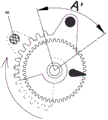
- CN
- China
- Prior art keywords
- gear
- electromechanical
- lock
- sector gear
- main
- Prior art date
- Legal status (The legal status is an assumption and is not a legal conclusion. Google has not performed a legal analysis and makes no representation as to the accuracy of the status listed.)
- Expired - Fee Related
Links
- 238000000926 separation method Methods 0.000 title claims abstract description 8
- 244000309464 bull Species 0.000 claims description 14
- 240000007643 Phytolacca americana Species 0.000 claims description 2
- 235000009074 Phytolacca americana Nutrition 0.000 claims description 2
- 238000003756 stirring Methods 0.000 claims 4
- 238000000034 method Methods 0.000 description 4
- 230000008901 benefit Effects 0.000 description 2
- 238000004519 manufacturing process Methods 0.000 description 2
- 238000012986 modification Methods 0.000 description 2
- 230000004048 modification Effects 0.000 description 2
- 230000008569 process Effects 0.000 description 2
- 230000004888 barrier function Effects 0.000 description 1
- 230000009286 beneficial effect Effects 0.000 description 1
- 238000010586 diagram Methods 0.000 description 1
- 238000005516 engineering process Methods 0.000 description 1
- 230000006698 induction Effects 0.000 description 1
- 238000003754 machining Methods 0.000 description 1
Images



Landscapes
- Lock And Its Accessories (AREA)
Abstract
The utility model discloses an electromechanical separation structure of electromechanical lock body, including lock shell and main spring bolt, the lock core of installing in the lock shell, the lock core passes through this main spring bolt of sector gear linkage, and sector gear is connected with main spring bolt, and the gear wheel is direct or indirect to be connected with the motor, the gear wheel is concentric with sector gear, and has the independent pivoted angle difference of permission sector gear between gear wheel and the sector gear. Therefore, the design between the large gear and the sector gear is very ingenious, and the angle difference exists, so that the large gear and the sector gear are separated when the lock is opened and closed manually, and the large gear and the sector gear are closed when the lock is opened and closed electrically. Therefore, the manual unlocking and locking is easy and labor-saving, the structure is simple, and the cost is low.
Description
Technical Field
The utility model belongs to the technical field of the lock technique and specifically relates to indicate an electromechanical separation structure of electromechanical lock body.
Background
In daily life, door locks are important barriers for guaranteeing property and privacy safety. With the development of society, the requirements of door locks on safety and convenience are increasing day by day. The door lock generally has two opening modes, namely an electric unlocking mode; a mechanical unlocking mode. The electric unlocking mode comprises an electronic lock head, a magnetic card, a TM card (button key), an ID induction card, a wireless remote control, a computer door lock control system, a fingerprint, an eye mask and other biological identification technologies. The mechanical unlocking mode is that a mechanical key matched with the anti-theft lock head is inserted into the exposed or hidden anti-theft lock head to unlock the lockset. The mechanical opening mode can be used in case of electrical failure or emergency special condition.
The mechanical unlocking part and the electrical unlocking part of the door lock are usually connected with an unlocking gear through a clutch, the electrical unlocking and the mechanical unlocking are not interfered mutually through the clutch, and the function of preventing violent unlocking is achieved. After power failure, when the door is opened by a handle or a key, the motor is driven to rotate together, the motor gear cannot idle, and the motor can be damaged after the door is opened violently. Moreover, the traditional clutch has the advantages of very complicated structure, low fault tolerance rate, very high requirements on machining and assembling precision, complex process and very high cost.
SUMMERY OF THE UTILITY MODEL
In view of the above, the present invention is directed to a mechanical and electrical separating structure of an electromechanical lock body, wherein the mechanical and electrical separating structure is "off" when the lock is opened or closed manually, and the mechanical and electrical separating structure is "on" when the lock is opened or closed electrically. Therefore, the manual unlocking and locking is easy and labor-saving, and simultaneously, the electric unlocking and locking function can be firmed.
In order to achieve the above purpose, the utility model adopts the following technical scheme:
the utility model provides an electromechanical separation structure of electromechanical lock body, includes lock shell and installs main spring bolt, the lock core in the lock shell, the lock core passes through this main spring bolt of sector gear linkage, and sector gear is connected with main spring bolt, and the gear wheel is direct or indirect and is connected with the motor, gear wheel and sector gear are concentric, and have the angle difference that allows sector gear independent rotation between gear wheel and the sector gear.
As a preferred scheme, a poking block is arranged on the large gear, an included angle a is formed between the first end face of the sector gear and the poking block, an included angle B is formed between the second end face of the sector gear and the poking block in a normal state, and the rotating angle of the sector gear when the sector gear pokes the main lock tongue to be locked is A ', wherein A' is less than A.
As a preferred scheme, the radius of the bull gear is smaller than that of the sector gear, the bull gear is overlapped on the inner side of the sector gear, and the bull gear penetrates through the vertical hole of the main bolt through a shaft connecting piece and then is assembled on the lock shell.
As a preferred scheme, the sector gear is provided with a tooth part and a main lock tongue poking part, the main lock tongue poking part protrudes out of the tooth part, and a poking convex column is arranged on the back surface of the main lock tongue poking part and extends into an inclined lock groove of the main lock tongue.
Preferably, the sector gear has a shaft connecting portion having a first shaft hole at a center thereof, the bull gear has a second shaft hole at a center thereof, the first shaft hole is opposite to the second shaft hole, and a shaft connecting member is assembled in the first shaft hole and the second shaft hole.
Preferably, the shifting block of the large gear is not lower than the surface of the sector gear.
Preferably, the output main shaft of the motor is connected with a scroll rod, the scroll rod is meshed with a small gear set, and the small gear is meshed with a large gear.
Preferably, the pinion gear is located on the right side of the bull gear, and the motor is located on the lower side of the pinion gear.
As a preferable scheme, a lock cylinder gear is arranged on the lock cylinder, and the lock cylinder gear is meshed with the sector gear.
Preferably, the cylinder gear is located to the left of the sector gear.
Compared with the prior art, the utility model obvious advantage and beneficial effect have, particularly, can know by above-mentioned technical scheme, the design between gear wheel and the sector gear is very ingenious, has between gear wheel and the sector gear to allow the independent pivoted angle difference of sector gear, and when manual division shutting, gear wheel and sector gear are "from", and when electronic division shutting, gear wheel and sector gear are "close". Therefore, the manual unlocking and locking is easy and labor-saving, the structure is simple, and the cost is low.
To illustrate the structural features and functions of the present invention more clearly, the present invention will be described in detail with reference to the accompanying drawings and specific embodiments.
Drawings
Fig. 1 is a schematic perspective view of an embodiment of the present invention.
Fig. 2 is a front view of fig. 1.
Fig. 3 is a schematic view of an unlocked state according to the embodiment of the present invention.
Fig. 4 is a schematic diagram of a locked state according to an embodiment of the present invention.
Fig. 5 is a schematic view illustrating the sector gear of the embodiment of the present invention being changed from the unlocked state to the locked state.
Fig. 6 is a schematic view of a sector gear according to an embodiment of the present invention.
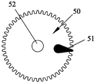
Fig. 7 is a schematic view of a gearwheel according to an embodiment of the present invention.
Fig. 8 is a schematic view of a sector gear and a gearwheel according to an embodiment of the present invention in a normal state.
The attached drawings indicate the following:
10. lock shell 20 and main bolt
21. Inclined lock groove 30 and lock cylinder
31. Lock core gear 40, sector gear
41. Shaft connector 42 and shaft connecting part
43. First shaft hole 44, tooth part
45. Main lock bolt striking part 46, striking convex column
50. Gearwheel 51, toggle block
52. Second shaft hole 60, motor
61. A worm 70, a pinion gear set.
Detailed Description
Referring to fig. 1 to 8, a specific structure of a preferred embodiment of the present invention is shown, which is an electromechanical separating structure of an electromechanical lock body, including a lock case 10, a main bolt 20 installed in the lock case 10, a lock cylinder 30, a sector gear 40, a gearwheel 50, and a motor 60. The lock core 30 is linked with the main bolt 20 through a sector gear 40, the sector gear 40 is connected with the main bolt 20, the motor 60 is directly or indirectly connected with a large gear 50, the large gear 50 is concentric with the sector gear 40, and an angle difference allowing the sector gear 40 to rotate independently is formed between the large gear 50 and the sector gear 40.
The bull gear 50 is provided with a toggle block 51, and the toggle block 51 of the bull gear 50 is not lower than the surface of the sector gear 40. Under normal state, an included angle a is formed between the first end surface of the sector gear 40 and the dial block 51, an included angle B is formed between the second end surface of the sector gear 40 and the dial block 51, and the rotation angle when the sector gear 40 dials the main bolt 20 to be locked is a ', wherein a' < a. This kind of design makes from the interior manual door that opens the door, perhaps when opening the door from the external key of door, the rotatory certain angle A 'that drives of lock core 30 can open the door of sector gear 40, because A' < A, also be the clockwise rotation of sector gear 40 and unblank, can not touch shifting block 51 yet, consequently at whole manual door opening in-process, gear wheel 50 can not rotate, consequently motor 60 just can not be pulled, the separation of mechanical unlocking and electric unlocking has been realized ingeniously, separation and reunion reasonable in design, light laborsaving, moreover, the steam generator is simple in structure, and is low in cost.
The radius of the bull gear 50 is smaller than that of the sector gear 40, and the bull gear 50 is overlapped inside the sector gear 40, passes through the vertical hole of the main bolt 20 through the shaft connector 41, and then is assembled to the lock case 10. More specifically, the sector gear 40 has a shaft connecting portion 42, a first shaft hole 43 is formed in the center of the shaft connecting portion 42, a second shaft hole 52 is formed in the center of the large gear 50, the first shaft hole 43 faces the second shaft hole 52, and the shaft connecting member 41 is assembled to the first shaft hole 43 and the second shaft hole 52 and then fixed to the lock case 10.
The output shaft of the motor 60 is connected with a scroll 61, the scroll 61 is engaged with a small gear set 70, and the small gear is engaged with the large gear 50. In this embodiment, the pinion gear is located on the right side of the bull gear 50, and the motor 60 is located on the lower side of the pinion gear. The key cylinder 30 is provided with a key cylinder gear 31, and the key cylinder gear 31 is engaged with the sector gear 40. The cylinder gear 31 is located on the left side of the sector gear 40. Each gear of this design distributes on a plane basically for the lock body can make thinlyer, and the equipment is more convenient, and production is easy, and the cost of manufacture is low.
The utility model provides a design between gear wheel 50 and sector gear 40 is very ingenious, and when manual unblock, gear wheel 50 and sector gear 40 are "from", and when electronic unblock, gear wheel 50 and sector gear 40 are "close".
The specific working process is as follows:
when the manual unlocking is carried out, a person inserts the lock core 30 by using a key from the outside of the door, or the person rotates the door handle from the inside of the door, the lock core 30 rotates to drive the lock core gear 31 and then drive the sector gear 40 to rotate anticlockwise, so that the main lock body is pulled downwards and retracts into the main lock hole, and then the unlocking is carried out.
When the lock is manually locked, the lock cylinder 30 is also rotated to drive the lock cylinder gear 31 and then drive the sector gear 40 to rotate clockwise, so that the main lock body is pushed upwards and is locked after extending out of the main lock hole. Therefore, it is understood that, in the manual unlocking, the large gear 50 does not operate, and the motor 60 and the small gear do not operate.
When the lock is unlocked electrically, the motor 60 rotates to drive the large gear 50 to rotate anticlockwise, the shifting block 51 can be blocked on the sector gear after the large gear 50 rotates anticlockwise by a certain angle, at the moment, the large gear 50 drives the sector gear 40 to rotate anticlockwise together, and the motor stops until the sector gear 40 drags the main bolt 20 to retract into the main lock hole completely.
During electronic locking, motor 60 rotates, drives gear wheel 50 clockwise rotation, and after gear wheel 50 clockwise rotation certain angle, shifting block 51 can keep off on sector gear, and gear wheel 50 drives sector gear 40 clockwise rotation together this moment, and the motor stops after sector gear 40 drags main spring bolt 20 and stretches out the main lockhole completely.
To sum up, the design of the present invention is focused on that the design between the large gear 50 and the sector gear 40 is very ingenious, the angle difference allowing the sector gear 40 to rotate independently is provided between the large gear 50 and the sector gear 40, when the lock is opened and closed manually, the large gear 50 and the sector gear 40 are "apart", and when the lock is opened and closed electrically, the large gear 50 and the sector gear 40 are "close". Therefore, the manual unlocking and locking is easy and labor-saving, the structure is simple, and the cost is low.
The above description is only a preferred embodiment of the present invention, and is not intended to limit the technical scope of the present invention, so that any slight modifications, equivalent changes and modifications made by the technical spirit of the present invention to the above embodiments are all within the scope of the technical solution of the present invention.
Claims (10)
1. The utility model provides an electromechanical separation structure of electromechanical lock body, includes the lock shell and installs main spring bolt, the lock core in the lock shell, its characterized in that: the lock core is linked with the main lock tongue through a sector gear, the sector gear is connected with the main lock tongue, the large gear is directly or indirectly connected with the motor, the large gear is concentric with the sector gear, and an angle difference allowing the sector gear to rotate independently is formed between the large gear and the sector gear.
2. The electromechanical decoupling structure of an electromechanical lock body of claim 1, wherein: the large gear is provided with a poking block, an included angle A is formed between the first end face of the sector gear and the poking block, an included angle B is formed between the second end face of the sector gear and the poking block, and the sector gear pokes the main bolt to rotate at an angle A 'when the main bolt is locked, wherein A' is less than A.
3. The electromechanical decoupling structure of an electromechanical lock body of claim 1, wherein: the radius of the bull gear is smaller than that of the sector gear, the bull gear is superposed on the inner side of the sector gear, and the bull gear penetrates through the vertical hole of the main spring bolt through the shaft connecting piece and then is assembled on the lock shell.
4. The electromechanical decoupling structure of an electromechanical lock body of claim 1, wherein: the sector gear is provided with a tooth part and a main lock tongue stirring part, the main lock tongue stirring part protrudes out of the tooth part, and a stirring convex column is arranged on the back surface of the main lock tongue stirring part and extends into an inclined lock groove of the main lock tongue.
5. The electromechanical decoupling structure of an electromechanical lock body of claim 1, wherein: the sector gear is provided with a shaft connecting part, a first shaft hole is formed in the center of the shaft connecting part, a second shaft hole is formed in the center of the large gear, the first shaft hole is opposite to the second shaft hole, and the shaft connecting piece is assembled in the first shaft hole and the second shaft hole.
6. The electromechanical decoupling structure of an electromechanical lock body of claim 1, wherein: and the poking block of the large gear is not lower than the surface of the sector gear.
7. The electromechanical decoupling structure of an electromechanical lock body of claim 1, wherein: the output main shaft of the motor is connected with a scroll bar which is meshed with a small gear set, and the small gear is meshed with a large gear.
8. The electromechanical breakaway structure of an electromechanical lock body of claim 7, wherein: the pinion is positioned on the right side of the bull gear, and the motor is positioned on the lower side of the pinion.
9. The electromechanical decoupling structure of an electromechanical lock body of claim 1, wherein: and a lock cylinder gear is arranged on the lock cylinder and is meshed with the sector gear.
10. The electromechanical breakaway structure of an electromechanical lock body of claim 9, wherein: the lock cylinder gear is located on the left side of the sector gear.
Priority Applications (1)
| Application Number | Priority Date | Filing Date | Title |
|---|---|---|---|
| CN201822257155.XU CN210122851U (en) | 2018-12-29 | 2018-12-29 | Electromechanical separation structure of electromechanical lock body |
Applications Claiming Priority (1)
| Application Number | Priority Date | Filing Date | Title |
|---|---|---|---|
| CN201822257155.XU CN210122851U (en) | 2018-12-29 | 2018-12-29 | Electromechanical separation structure of electromechanical lock body |
Publications (1)
| Publication Number | Publication Date |
|---|---|
| CN210122851U true CN210122851U (en) | 2020-03-03 |
Family
ID=69631886
Family Applications (1)
| Application Number | Title | Priority Date | Filing Date |
|---|---|---|---|
| CN201822257155.XU Expired - Fee Related CN210122851U (en) | 2018-12-29 | 2018-12-29 | Electromechanical separation structure of electromechanical lock body |
Country Status (1)
| Country | Link |
|---|---|
| CN (1) | CN210122851U (en) |
Cited By (1)
| Publication number | Priority date | Publication date | Assignee | Title |
|---|---|---|---|---|
| CN111173410A (en) * | 2020-03-09 | 2020-05-19 | 广州市好的门窗有限公司 | Manual-automatic integrated clutch lock and manual-electric integrated folding door and window |
-
2018
- 2018-12-29 CN CN201822257155.XU patent/CN210122851U/en not_active Expired - Fee Related
Cited By (1)
| Publication number | Priority date | Publication date | Assignee | Title |
|---|---|---|---|---|
| CN111173410A (en) * | 2020-03-09 | 2020-05-19 | 广州市好的门窗有限公司 | Manual-automatic integrated clutch lock and manual-electric integrated folding door and window |
Similar Documents
| Publication | Publication Date | Title |
|---|---|---|
| CN103774925B (en) | A kind of dynamo-electric double opening lock | |
| CN202299736U (en) | Safe burglarproof lock | |
| CN106337602B (en) | Safe-guard door lock | |
| CN208564216U (en) | The emergent unlocking of smart lock and lock two-in-one device | |
| CN209761052U (en) | Electromechanical lock body | |
| CN110359776B (en) | Electromechanical lock | |
| CN215978878U (en) | an electronic lock | |
| CN206035136U (en) | Electronic anti -theft lock | |
| CN211058492U (en) | Electromechanical lock | |
| CN220395418U (en) | Electric lock body | |
| CN208430892U (en) | Lockset and door-plate system | |
| CN219431573U (en) | Antitheft lock with emergency escape capability | |
| CN219281485U (en) | A fully automatic lock body | |
| CN211173527U (en) | Novel separation and reunion lock body mechanism of intelligence lock | |
| CN110930554B (en) | Intelligent lock body with anti-pry function and door equipped with the lock body | |
| CN219491984U (en) | Mechanical electronic lock of medical movable cabinet | |
| CN104213775B (en) | Physical-distribution intelligent locks dual locking clutch | |
| CN208010093U (en) | A kind of smart lock driving device | |
| CN209799614U (en) | Motor type automatic blade lock | |
| CN208816011U (en) | Anti-locking electronic door lock | |
| CN209494345U (en) | Mechanical and electronic combined safety lock | |
| CN115613909A (en) | A three-open two-lock assembly and a vault door locking mechanism | |
| CN209837946U (en) | Front-end mechanical coded door lock | |
| CN201526206U (en) | Emergency opening mechanism of electronic safety box | |
| CN223459233U (en) | Door lock structure and intelligent door |
Legal Events
| Date | Code | Title | Description |
|---|---|---|---|
| GR01 | Patent grant | ||
| GR01 | Patent grant | ||
| CF01 | Termination of patent right due to non-payment of annual fee |
Granted publication date: 20200303 Termination date: 20211229 |
|
| CF01 | Termination of patent right due to non-payment of annual fee |