CN210115751U - Small Auger Bit Sharpener - Google Patents
Small Auger Bit Sharpener Download PDFInfo
- Publication number
- CN210115751U CN210115751U CN201920079752.XU CN201920079752U CN210115751U CN 210115751 U CN210115751 U CN 210115751U CN 201920079752 U CN201920079752 U CN 201920079752U CN 210115751 U CN210115751 U CN 210115751U
- Authority
- CN
- China
- Prior art keywords
- pair
- install
- bevel gear
- plate
- lead screw
- Prior art date
- Legal status (The legal status is an assumption and is not a legal conclusion. Google has not performed a legal analysis and makes no representation as to the accuracy of the status listed.)
- Expired - Fee Related
Links
- 238000005498 polishing Methods 0.000 claims 2
- 230000008878 coupling Effects 0.000 claims 1
- 238000010168 coupling process Methods 0.000 claims 1
- 238000005859 coupling reaction Methods 0.000 claims 1
- 238000012545 processing Methods 0.000 abstract description 5
- 238000005520 cutting process Methods 0.000 abstract description 4
- 238000013461 design Methods 0.000 abstract description 4
- 230000001186 cumulative effect Effects 0.000 abstract description 3
- 238000012549 training Methods 0.000 abstract description 3
- 230000009286 beneficial effect Effects 0.000 abstract 1
- 238000010586 diagram Methods 0.000 description 7
- 238000004519 manufacturing process Methods 0.000 description 4
- 238000000034 method Methods 0.000 description 4
- 230000000694 effects Effects 0.000 description 3
- 238000005553 drilling Methods 0.000 description 1
- 238000009434 installation Methods 0.000 description 1
- 238000003754 machining Methods 0.000 description 1
- 238000012423 maintenance Methods 0.000 description 1
Images


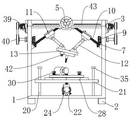

Landscapes
- Finish Polishing, Edge Sharpening, And Grinding By Specific Grinding Devices (AREA)
Abstract
本实用新型公开了一种小型螺旋钻头刃磨机,包括机架,所述机架的底部四角处安装有两对结构相同的脚座,所述机架上安装有控制装夹单元,所述机架的底部处安装有工作台单元。本实用新型的有益效果是,操作简单,不需要进行专业培训,适应各层次的操作人员;很多零件都是常见件,使用者可以按此设计自已制作;更换装夹装置,可以刃磨片状直线刃刀具,如菜单、铡刀、匕首、剪刀等,或片状曲线刃具,如钩刀、镰刀等;可以对本设备进行机电控制,实现四轴联动,使加工更精确;控制部分累积误差小、精度较高、运动部分重量轻、速度高、动态响应好、结构紧凑、刚度高、承载能力大。
The utility model discloses a small spiral drill bit sharpening machine, which comprises a frame, two pairs of foot seats with the same structure are installed at the four corners of the bottom of the frame, a control clamping unit is installed on the frame, and the A workbench unit is installed at the bottom of the rack. The beneficial effect of the utility model is that the operation is simple, no professional training is required, and it is suitable for operators at all levels; many parts are common parts, and users can design and make their own; straight-line cutting tools, such as menus, guillotine knives, daggers, scissors, etc., or flaky curved cutting tools, such as hook knives, sickles, etc.; this equipment can be electromechanically controlled to realize four-axis linkage, making processing more accurate; the cumulative error of the control part is small , High precision, light weight of moving parts, high speed, good dynamic response, compact structure, high rigidity and large bearing capacity.
Description
技术领域technical field
本实用新型涉及刃磨机技术领域,特别是小型螺旋钻头刃磨机。The utility model relates to the technical field of sharpening machines, in particular to a small spiral drill bit sharpening machine.
背景技术Background technique
在机械孔加工中,螺旋钻头使用时间长后,钻头就会磨损,会影响加工效率和精度。如果进行更换会造成刀具浪费,特别对于一些昂贵的螺旋钻刀具成本增加更大。In mechanical hole processing, after the auger bit is used for a long time, the drill bit will wear out, which will affect the processing efficiency and accuracy. If it is replaced, the tool will be wasted, especially for some expensive auger tools.
目前,使用较多的螺旋钻头刃磨机包括大型机和小型机两种。分别是例如公告号为CN 101774128 A 的发明专利以及公告号为CN 1299727的发明专利,它们在结构上都是做水平面进给运动,工作空间小,刀具角度变换小。大型机结构复杂、部件多、制造成本高、维护费用高、占用空间大、设备沉重;小型机加工精度低、工作时易振动且稳定性差。At present, the most commonly used auger sharpeners include two types: large machines and small machines. They are, for example, the invention patent with the publication number CN 101774128 A and the invention patent with the publication number CN 1299727, both of which are structurally capable of horizontal plane feed movement, with small working space and small tool angle change. Mainframes have complex structures, many components, high manufacturing costs, high maintenance costs, large footprints, and heavy equipment; small machines have low machining accuracy, are prone to vibration during work, and have poor stability.
发明内容SUMMARY OF THE INVENTION
本实用新型的目的是为了解决上述问题,设计了小型螺旋钻头刃磨机。The purpose of this utility model is to solve the above problems, and design a small spiral drill sharpening machine.
实现上述目的本实用新型的技术方案为,小型螺旋钻头刃磨机,包括机架,所述机架的底部四角处安装有两对结构相同的脚座,所述机架的前壁面上且位于顶部处安装有刻度尺,所述机架上安装有控制装夹单元,所述机架的底部处安装有工作台单元。The technical scheme of the present invention to achieve the above-mentioned purpose is that a small auger bit sharpening machine includes a frame, two pairs of feet with the same structure are installed at the bottom four corners of the frame, and the front wall of the frame is located on the front wall of the frame. A scale is installed at the top, a control clamping unit is installed on the frame, and a workbench unit is installed at the bottom of the frame.
优选的,所述控制装夹单元,包括:横移结构,所述机架上安装有横移结构,所述横移结构的底部安装有一对结构相同的活动结构,一对所述活动结构的底部处安装有装夹结构。Preferably, the control clamping unit includes: a traverse structure, a traverse structure is installed on the frame, a pair of movable structures with the same structure are installed at the bottom of the traverse structure, and a pair of movable structures are installed on the bottom of the traverse structure. A clamping structure is installed at the bottom.
优选的,所述横移结构,包括:拖板,所述机架上滑动安装有拖板,所述拖板上开设有第一螺孔,所述机架上转动安装有第一丝杠,所述第一丝杆通过第一螺孔与拖板螺旋相连,所述第一丝杠的左端面上安装有第一手轮。Preferably, the traverse structure includes: a carriage, a carriage is slidably installed on the frame, a first screw hole is formed on the carriage, and a first lead screw is rotatably mounted on the frame, The first lead screw is screwed with the carriage through a first screw hole, and a first hand wheel is installed on the left end surface of the first lead screw.
优选的,所述活动结构,包括:连接轴承,所述拖板的内侧壁面上且靠近底部处安装有连接轴承,所述连接轴承上插装有第一伞形齿轮,所述拖板的外侧壁面上转动安装有第二手轮,所述第二手轮的前端面上安装有第二伞形齿轮,所述第二伞形齿轮与第一伞形齿轮啮合相连,所述第一伞形齿轮上固接有第二丝杠,所述第二丝杠的上端面与拖板转动相连,所述第二丝杠上安装有滑块,所述滑块与第二丝杠螺纹相连,所述滑块的下壁面上活动安装有连杆。Preferably, the movable structure includes: a connecting bearing, a connecting bearing is installed on the inner side wall of the carriage and near the bottom, a first bevel gear is inserted on the connecting bearing, and the outer side of the carriage is A second hand wheel is rotatably installed on the wall surface, a second bevel gear is installed on the front end surface of the second hand wheel, the second bevel gear is meshed and connected with the first bevel gear, and the first bevel gear is A second lead screw is fixed on the gear, the upper end surface of the second lead screw is rotatably connected with the carriage, a slider is installed on the second lead screw, and the slider is threadedly connected with the second lead screw, so A connecting rod is movably installed on the lower wall of the slider.
优选的,所述装夹结构,包括:底座,一对所述连杆的下端面上活动安装有底座,所述底座内安装有旋转气缸,所述旋转气缸的旋转端面上安装有插板,所述插板上安装有盖板,所述插板上插装有钻头,所述钻头依次贯穿盖板与插板,所述钻头的外环面上且位于盖板与插板之间安装有接板,所述盖板上左右两侧处安装有一对结构相同的凸块,一对所述凸块依次贯穿接板与插板,所述插板的下壁面左右两侧处开设有一对结构相同的第二螺孔,一对所述第一螺栓插装于盖板的下壁面上,一对所述第一螺栓依次贯穿盖板以及凸块且与第二螺孔螺旋相连,所述底座的下壁面上安装有角度传感器。Preferably, the clamping structure includes: a base, a base is movably installed on the lower end surfaces of a pair of the connecting rods, a rotating cylinder is installed in the base, and a plug plate is installed on the rotating end surface of the rotating cylinder, A cover plate is installed on the insert plate, a drill bit is inserted on the insert plate, the drill bit penetrates the cover plate and the insert plate in sequence, and a drill bit is installed on the outer ring surface of the drill bit and located between the cover plate and the insert plate. A connecting plate, a pair of bumps with the same structure are installed on the left and right sides of the cover plate, a pair of the bumps pass through the connecting plate and the inserting plate in turn, and a pair of structures are opened on the left and right sides of the lower wall of the inserting plate The same second screw holes, a pair of the first bolts are inserted on the lower wall surface of the cover plate, a pair of the first bolts pass through the cover plate and the bumps in turn and are connected with the second screw holes in a spiral, the base An angle sensor is installed on the lower wall of the .
优选的,所述工作台单元,包括:升降结构,所述机架的底部处安装有升降结构,所述升降结构上安装有滑动打磨结构。Preferably, the worktable unit includes: a lifting structure, a lifting structure is installed at the bottom of the frame, and a sliding grinding structure is installed on the lifting structure.
优选的,所述升降结构,包括:两对结构相同的导柱,所述机架的内下壁面上安装有两对所述导柱,两对所述导柱上安装有底板,所述机架的内下壁面上且位于底板的下部处安装有一对结构相同的轴承桥座,一对所述轴承桥座之间插装有转杆,所述转杆的前端面上安装有第三手轮,所述转杆的后端面上安装有第三伞形齿轮,所述机架的内下壁面上且靠近后部处转动安装有第四伞形齿轮,所述第四伞形齿轮与第三伞形齿轮啮合相连,所述第四伞形齿轮上安装有第三丝杠,所述底板上开设有第三螺孔,所述第三丝杠通过第三螺孔与底板螺旋相连。Preferably, the lifting structure includes: two pairs of guide posts with the same structure, two pairs of the guide posts are installed on the inner and lower walls of the frame, and bottom plates are installed on the two pairs of the guide posts, and the machine A pair of bearing bridge seats with the same structure are installed on the inner and lower walls of the frame and located at the lower part of the bottom plate, a rotating rod is inserted between the pair of bearing bridge seats, and a third hand is installed on the front end surface of the rotating rod. A third bevel gear is installed on the rear end surface of the rotating rod, and a fourth bevel gear is rotatably installed on the inner lower wall of the frame and close to the rear. The three bevel gears are meshed and connected, a third lead screw is installed on the fourth bevel gear, a third screw hole is opened on the bottom plate, and the third lead screw is screwed with the bottom plate through the third screw hole.
优选的,所述滑动打磨结构,包括:第一垫板,所述底板上安装有第一垫板,所述第一垫板上转动安装有第二垫板,所述第一垫板上开设有若干结构相同的插孔,所述第二垫板上插装有一对结构相同的第二螺栓,所述第二垫板上滑动安装有电机座,所述电机座上安装有砂轮机,所述电机座的前后两侧处插装有一对结构相同的第三螺栓,一对所述第三螺栓的下端面上安装有一对结构相同的压板,一对所述压板与第二垫板相触碰。Preferably, the sliding grinding structure includes: a first backing plate, a first backing plate is installed on the bottom plate, a second backing plate is rotatably mounted on the first backing plate, and the first backing plate is opened There are several jacks with the same structure, a pair of second bolts with the same structure are inserted on the second backing plate, a motor seat is slidably installed on the second backing plate, and a grinding wheel is installed on the motor seat, so the A pair of third bolts with the same structure are inserted at the front and rear sides of the motor base, a pair of pressure plates with the same structure are installed on the lower end surfaces of the pair of third bolts, and a pair of the pressure plates are in contact with the second backing plate bump.
优选的,两对所述导柱上安装有两对结构相同的卡块。Preferably, two pairs of clamping blocks with the same structure are installed on the two pairs of the guide posts.
优选的,若干所述插孔其数量为八个。Preferably, the number of the jacks is eight.
利用本实用新型的技术方案制作的小型螺旋钻头刃磨机,结构简单,零件少,制造成本低;可实现X、Y、Z、C轴的四轴运动,工作空间大,角度控制精确;操作简单,不需要进行专业培训,适应各层次的操作人员;很多零件都是常见件,使用者可以按此设计自已制作;更换装夹装置,可以刃磨片状直线刃刀具,如菜单、铡刀、匕首、剪刀等,或片状曲线刃具,如钩刀、镰刀等;可以对本设备进行机电控制,实现四轴联动,使加工更精确;控制部分累积误差小、精度较高、运动部分重量轻、速度高、动态响应好、结构紧凑、刚度高、承载能力大。The small helical drill sharpening machine produced by the technical scheme of the utility model has the advantages of simple structure, few parts and low manufacturing cost; it can realize four-axis motion of X, Y, Z, and C axes, with large working space and precise angle control; Simple, no professional training is required, and it is suitable for operators at all levels; many parts are common parts, and users can design and make their own according to this; change the clamping device, and can sharpen flaky straight-edged knives, such as menus, guillotine knives , daggers, scissors, etc., or flaky curved cutting tools, such as hook knives, sickles, etc.; the equipment can be electromechanically controlled to realize four-axis linkage, making processing more accurate; the control part has small cumulative error, high precision, and light weight of the moving part , High speed, good dynamic response, compact structure, high rigidity and large bearing capacity.
附图说明Description of drawings
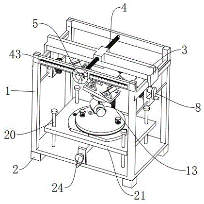
图1是本实用新型的结构示意图;Fig. 1 is the structural representation of the present utility model;
图2是本实用新型的主视结构示意图;Fig. 2 is the front view structure schematic diagram of the present utility model;
图3是本实用新型的右视结构示意图;Fig. 3 is the right side view structure schematic diagram of the present utility model;
图4是本实用新型的俯视结构示意图;Fig. 4 is the top view structure schematic diagram of the present utility model;
图5是本实用新型的装夹结构示意图;5 is a schematic diagram of the clamping structure of the present invention;
图6是本实用新型的装夹结构局部放大示意图;Fig. 6 is a partial enlarged schematic view of the clamping structure of the present invention;
图7是本实用新型的滑动打磨结构示意图;7 is a schematic view of the sliding grinding structure of the present invention;
图8是本实用新型的实施例二结构示意图;8 is a schematic structural diagram of
图9是本实用新型的实施例三结构示意图;9 is a schematic structural diagram of
图10是本实用新型的实施例四结构示意图;10 is a schematic structural diagram of
图中,1、机架;2、脚座;3、拖板;4、第一丝杠;5、第一手轮;6、连接轴承;7、第一伞形齿轮;8、第二手轮;9、第二伞形齿轮;10、第二丝杠;11、滑块;12、连杆;13、底座;14、旋转气缸;15、插板;16、盖板;17、钻头;18、接板;19、第一螺栓;20、导柱;21、底板;22、轴承桥座;23、转杆;24、第三手轮;25、第三伞形齿轮;26、第四伞形齿轮;27、第三丝杠;28、第一垫板;29、第二垫板;30、第二螺栓;31、电机座;32、砂轮机;33、第三螺栓;34、压板;35、卡块;36、第一伺服电机;37、第五伞形齿轮;38、第六伞形齿轮;39、第二伺服电机;40、滚轮;41、第三伺服电机;42、角度传感器;43、刻度尺。In the figure, 1, the frame; 2, the foot seat; 3, the carriage; 4, the first lead screw; 5, the first hand wheel; 6, the connecting bearing; 7, the first bevel gear; 8, the second hand Wheel; 9. Second bevel gear; 10. Second lead screw; 11. Slider; 12. Connecting rod; 13. Base; 14. Rotary cylinder; 15. Insert plate; 16. Cover plate; 18, connecting plate; 19, first bolt; 20, guide column; 21, bottom plate; 22, bearing bridge seat; 23, rotating rod; 24, third hand wheel; 25, third bevel gear; 26, fourth Bevel gear; 27, the third screw; 28, the first pad; 29, the second pad; 30, the second bolt; 31, the motor seat; 32, the grinding machine; 33, the third bolt; 34, the pressure plate ;35, block; 36, the first servo motor; 37, the fifth bevel gear; 38, the sixth bevel gear; 39, the second servo motor; 40, the roller; 41, the third servo motor; 42, the angle sensor; 43, scale.
具体实施方式Detailed ways
下面结合附图对本实用新型进行具体描述,如图1-10所示,小型螺旋钻头17刃磨机,包括机架1,所述机架1的底部四角处安装有两对结构相同的脚座2,所述机架1的前壁面上且位于顶部处安装有刻度尺43,所述机架1上安装有控制装夹单元,所述机架1的底部处安装有工作台单元,所述控制装夹单元,包括:横移结构,所述机架1上安装有横移结构,所述横移结构的底部安装有一对结构相同的活动结构,一对所述活动结构的底部处安装有装夹结构,所述横移结构,包括:拖板3,所述机架1上滑动安装有拖板3,所述拖板3上开设有第一螺孔,所述机架1上转动安装有第一丝杠4,所述第一丝杆通过第一螺孔与拖板3螺旋相连,所述第一丝杠4的左端面上安装有第一手轮5,所述活动结构,包括:连接轴承6,所述拖板3的内侧壁面上且靠近底部处安装有连接轴承6,所述连接轴承6上插装有第一伞形齿轮7,所述拖板3的外侧壁面上转动安装有第二手轮8,所述第二手轮8的前端面上安装有第二伞形齿轮9,所述第二伞形齿轮9与第一伞形齿轮7啮合相连,所述第一伞形齿轮7上固接有第二丝杠10,所述第二丝杠10的上端面与拖板3转动相连,所述第二丝杠10上安装有滑块11,所述滑块11与第二丝杠10螺纹相连,所述滑块11的下壁面上活动安装有连杆12,所述装夹结构,包括:底座13,一对所述连杆12的下端面上活动安装有底座13,所述底座13内安装有旋转气缸14,所述旋转气缸14的旋转端面上安装有插板15,所述插板15上安装有盖板16,所述插板15上插装有钻头17,所述钻头17依次贯穿盖板16与插板15,所述钻头17的外环面上且位于盖板16与插板15之间安装有接板18,所述盖板16上左右两侧处安装有一对结构相同的凸块,一对所述凸块依次贯穿接板18与插板15,所述插板15的下壁面左右两侧处开设有一对结构相同的第二螺孔,一对所述第一螺栓19插装于盖板16的下壁面上,一对所述第一螺栓19依次贯穿盖板16以及凸块且与第二螺孔螺旋相连,所述底座13的下壁面上安装有角度传感器42,所述工作台单元,包括:升降结构,所述机架1的底部处安装有升降结构,所述升降结构上安装有滑动打磨结构,所述升降结构,包括:两对结构相同的导柱20,所述机架1的内下壁面上安装有两对所述导柱20,两对所述导柱20上安装有底板21,所述机架1的内下壁面上且位于底板21的下部处安装有一对结构相同的轴承桥座22,一对所述轴承桥座22之间插装有转杆23,所述转杆23的前端面上安装有第三手轮24,所述转杆23的后端面上安装有第三伞形齿轮25,所述机架1的内下壁面上且靠近后部处转动安装有第四伞形齿轮26,所述第四伞形齿轮26与第三伞形齿轮25啮合相连,所述第四伞形齿轮26上安装有第三丝杠27,所述底板21上开设有第三螺孔,所述第三丝杠27通过第三螺孔与底板21螺旋相连,所述滑动打磨结构,包括:第一垫板28,所述底板21上安装有第一垫板28,所述第一垫板28上转动安装有第二垫板29,所述第一垫板28上开设有若干结构相同的插孔,所述第二垫板29上插装有一对结构相同的第二螺栓30,所述第二垫板29上滑动安装有电机座31,所述电机座31上安装有砂轮机32,所述电机座31的前后两侧处插装有一对结构相同的第三螺栓33,一对所述第三螺栓33的下端面上安装有一对结构相同的压板34,一对所述压板34与第二垫板29相触碰,两对所述导柱20上安装有两对结构相同的卡块35,若干所述插孔其数量为八个。The present utility model will be described in detail below with reference to the accompanying drawings. As shown in Figures 1-10, a
本实施方案的特点为,包括机架1,其特征在于,机架1的底部四角处安装有两对结构相同的脚座2,机架1上安装有控制装夹单元,机架1的底部处安装有工作台单元结构简单,零件少,制造成本低;可实现X、Y、Z、C轴的四轴运动,工作空间大,角度控制精确;操作简单,不需要进行专业培训,适应各层次的操作人员;很多零件都是常见件,使用者可以按此设计自已制作;更换装夹装置,可以刃磨片状直线刃刀具,如菜单、铡刀、匕首、剪刀等,或片状曲线刃具,如钩刀、镰刀等;可以对本设备进行机电控制,实现四轴联动,使加工更精确;控制部分累积误差小、精度较高、运动部分重量轻、速度高、动态响应好、结构紧凑、刚度高、承载能力大。The feature of this embodiment is that it includes a
下列为本案的各电器件型号及作用:The following is the model and function of each electrical device in this case:
砂轮机:型号为ESA-YS3040FN001,用于打磨工件。Grinder: Model ESA-YS3040FN001, used for grinding workpieces.
旋转气缸:型号为MSQB20A,用于带动钻头转动。Rotary cylinder: Model MSQB20A, used to drive the drill bit to rotate.
第一伺服电机:型号为SGDM-02ADA,由型号为JASD4002-20Z的伺服驱动器控制,用于带动第一丝杠转动,取代的第一手轮的扳动。The first servo motor: the model is SGDM-02ADA, which is controlled by the servo driver of the model JASD4002-20Z, which is used to drive the first lead screw to rotate and replace the pulling of the first hand wheel.
第二伺服电机:型号为SGDM-02ADA,由型号为JASD4002-20Z的伺服驱动器控制,用于带动第二丝杠转动,取代的第二手轮的扳动。The second servo motor: the model is SGDM-02ADA, which is controlled by the servo driver of the model JASD4002-20Z, which is used to drive the second lead screw to rotate, replacing the pulling of the second hand wheel.
第三伺服电机:型号为SGDM-02ADA,由型号为JASD4002-20Z的伺服驱动器控制,用于带动第三丝杠转动,取代的第三手轮的扳动。The third servo motor: the model is SGDM-02ADA, which is controlled by the servo driver of the model JASD4002-20Z, which is used to drive the third lead screw to rotate, instead of the third hand wheel.
角度传感器:型号为SSA00XXH2-V010,连接有外部显示屏,调整底座角度时,可以将准确的角度信息反馈出去,并在显示屏上显示,以告知操作人员调解的角度具体为多少,增加了调解的准确性。Angle sensor: Model SSA00XXH2-V010, connected to an external display screen, when adjusting the angle of the base, the accurate angle information can be fed back and displayed on the display screen to inform the operator of the specific angle to be adjusted. accuracy.
下列为本案的各组件型号及作用:The following is the model and function of each component in this case:
第二丝杠:第二丝杠与拖板之间呈斜角安装,较现在市面上的水平丝杠,这样安装会使第二丝杠获得更大的刚性,在底座较重时也可以保证钻头的稳定性。Second lead screw: The second lead screw and the carriage are installed at an oblique angle. Compared with the horizontal lead screw on the market, this installation will make the second lead screw more rigid, which can also be guaranteed when the base is heavier. Stability of the drill.
滑块:滑块上设有竖直的锥形凸点,用以与刻度尺上的刻度相对应。Slider: There are vertical conical bumps on the slider to correspond with the scale on the scale.
刻度尺:由于第二丝杠与拖板之间的夹角一定,所以可以根据滑块上的凸点所对应的刻度,通过勾股定理即可算出滑块在第二丝杠上的行距,由于钻头的位置与两个滑块在第二丝杠上滑动后的位置是一一对应的,因此以这种方式便可以准确定位钻头在两个滑块不同行距时的位置,使钻磨更加精准。Scale: Since the angle between the second lead screw and the carriage is fixed, the line spacing of the slider on the second lead screw can be calculated by the Pythagorean theorem according to the scale corresponding to the bump on the slider. Since the position of the drill bit is in one-to-one correspondence with the positions of the two sliders after sliding on the second lead screw, the position of the drill bit when the two sliders have different row spacings can be accurately positioned in this way, which makes drilling and grinding more efficient. Precise.
通过本领域人员,将本案中所有电气件与其适配的电源通过导线进行连接,并且应该根据实际情况,选择合适的控制器,以满足控制需求,具体连接以及控制顺序,应参考下述工作原理中,各电气件之间先后工作顺序完成电性连接,其详细连接手段,为本领域公知技术,下述主要介绍工作原理以及过程,不在对电气控制做说明。All the electrical components in this case are connected with the power supply to which they are adapted through wires by those skilled in the art, and an appropriate controller should be selected according to the actual situation to meet the control requirements. The specific connection and control sequence should refer to the following working principles Among them, the electrical connection between the electrical components is completed in sequence, and the detailed connection means are known in the art. The following mainly introduces the working principle and process, and does not describe the electrical control.
实施例一: 旋转第一手轮带动第一丝杠转动,拖板在第一丝杠转动的过程,会顺着与机架之间的滑道,沿Z轴运动,旋转第二手轮会使滑块顺着第二丝杠上移或者下移,通过连杆带动底座移动,做Y轴运动,通过两侧连杆运动的程度不同,使底座产生倾角或是水平升降,通过旋转第二垫板可以使砂轮机旋转到合适的角度,然后拧下第二螺栓,使其插入对应的插孔中,后推动砂轮机,使其顺着与第二垫板之间的滑道,前或者后移,到达合适的位置以后,拧下第三螺栓,使压板压在第二垫板上,通过第二垫板与压板之间的摩擦力,将砂轮机固定,后启动砂轮机进行打磨操作即可,当需要将砂轮机升起时,可以通过慢慢旋转第三手轮的方式,使连杆上的第三伞形齿轮转动,并带动第四伞形齿轮转动,使第三丝杠转动,随着第三丝杠转动,底板由于不能转动,从而与第三丝杠相对转动,从而根据第三丝杠的转动方向,向上或是向下移动,带动砂轮机升高或是降低,使砂轮与钻头接触,进行磨削,磨削完成后,反向旋转第三手轮降低工作台,关闭砂轮机即可,当需要更换钻头时,首先拧出第一螺栓,然后将其出去,顺着钻头抽出盖板,然后将钻头拔下,将新的钻头插入插板中,然后将盖板盖回,使凸块依次插进接板与插板上的凹槽内,然后将第一螺栓拧回第一螺孔,这样不仅防止钻头在机器工作时脱落,而且防止其左右晃动,拆装过程较为方便。Example 1: Rotating the first hand wheel drives the first lead screw to rotate. During the rotation of the first lead screw, the carriage will move along the Z axis along the slideway between the carriage and the frame. Make the slider move up or down along the second lead screw, drive the base to move through the connecting rod, and perform Y-axis movement. The backing plate can make the grinder rotate to a proper angle, then unscrew the second bolt and insert it into the corresponding socket, and then push the grinding machine to make it follow the slideway between the second backing plate and the front or Move back, after reaching the proper position, unscrew the third bolt to press the pressure plate on the second pad, fix the grinder through the friction between the second pad and the pressure plate, and then start the grinder for grinding operation That is, when the grinding machine needs to be lifted, the third bevel gear on the connecting rod can be rotated by slowly rotating the third handwheel, and the fourth bevel gear can be driven to rotate, so that the third lead screw can be rotated. Rotation, with the rotation of the third lead screw, the bottom plate can not rotate, so it rotates relative to the third lead screw, so as to move up or down according to the rotation direction of the third lead screw, driving the grinder to raise or lower, Make the grinding wheel contact the drill bit to perform grinding. After the grinding is completed, rotate the third hand wheel in the opposite direction to lower the worktable and turn off the grinding wheel machine. Pull out the cover plate along the drill bit, then pull out the drill bit, insert the new drill bit into the insert plate, then cover the cover plate back so that the bumps are inserted into the grooves on the insert plate and the insert plate in turn, and then insert the first The bolt is screwed back to the first screw hole, which not only prevents the drill from falling off when the machine is working, but also prevents it from shaking left and right, and the disassembly process is more convenient.
实施例二:当把实施例一中的第一手轮取下后,并在第一丝杠的后端面上安装第五伞形齿轮,在机架上安装第一伺服电机,在第一伺服电机上安装第六伞形齿轮使第五伞形齿轮与第六伞形齿轮啮合相连,通过第一伺服电机的带动使第一丝杆转动,取代了原来通过第一手轮扳动的方式,其他结构不变,也能带动横移前后移动拖板的效果,虽然成本有所提高,但是节约人力,且伺服电机扳动第一丝杆转动角度更加精准。Embodiment 2: After removing the first hand wheel in
实施例三:当把实施例一中的第二手轮取下,然后装上滚轮,并在机架两侧装上第二伺服电机,通过皮带将伺服电机的旋转端面与滚轮相连,第二伺服电机转动,通过皮带带动第二伞形齿轮转动,其他结构不变,也能达到带动第二丝杠转动的效果,虽然成本有所提高,但是节约人力,且伺服电机扳动第一丝杆转动角度更加精准。Embodiment 3: When the second hand wheel in
实施例四:当把实施例一中的第三手轮取下,然后将机架的内下壁面上安装第三伺服电机,使第三伞形齿轮的前端直接与第三伺服电机相连接,其他结构不变,也可以达到带动第四伞形齿轮与第三丝杠转动的效果,虽然成本有所提高,但是节约人力,且伺服电机扳动第一丝杆转动角度更加精准。Embodiment 4: When the third handwheel in
上述技术方案仅体现了本实用新型技术方案的优选技术方案,本技术领域的技术人员对其中某些部分所可能做出的一些变动均体现了本实用新型的原理,属于本实用新型的保护范围之内。The above technical solutions only reflect the preferred technical solutions of the technical solutions of the present invention, and some changes that those skilled in the art may make to some parts of them all reflect the principles of the present invention and belong to the protection scope of the present invention. within.
Claims (10)
Priority Applications (1)
| Application Number | Priority Date | Filing Date | Title |
|---|---|---|---|
| CN201920079752.XU CN210115751U (en) | 2019-01-17 | 2019-01-17 | Small Auger Bit Sharpener |
Applications Claiming Priority (1)
| Application Number | Priority Date | Filing Date | Title |
|---|---|---|---|
| CN201920079752.XU CN210115751U (en) | 2019-01-17 | 2019-01-17 | Small Auger Bit Sharpener |
Publications (1)
| Publication Number | Publication Date |
|---|---|
| CN210115751U true CN210115751U (en) | 2020-02-28 |
Family
ID=69611254
Family Applications (1)
| Application Number | Title | Priority Date | Filing Date |
|---|---|---|---|
| CN201920079752.XU Expired - Fee Related CN210115751U (en) | 2019-01-17 | 2019-01-17 | Small Auger Bit Sharpener |
Country Status (1)
| Country | Link |
|---|---|
| CN (1) | CN210115751U (en) |
Cited By (1)
| Publication number | Priority date | Publication date | Assignee | Title |
|---|---|---|---|---|
| CN109676447A (en) * | 2019-01-17 | 2019-04-26 | 沈阳工程学院 | A kind of compact spiral drill point grinder |
-
2019
- 2019-01-17 CN CN201920079752.XU patent/CN210115751U/en not_active Expired - Fee Related
Cited By (1)
| Publication number | Priority date | Publication date | Assignee | Title |
|---|---|---|---|---|
| CN109676447A (en) * | 2019-01-17 | 2019-04-26 | 沈阳工程学院 | A kind of compact spiral drill point grinder |
Similar Documents
| Publication | Publication Date | Title |
|---|---|---|
| CN204673400U (en) | Abnormity material hypotenuse or periphery machining tool | |
| CN107186602B (en) | Five-axis numerical control polishing machine | |
| CN110842599B (en) | Milling machine convenient to fix work piece | |
| CN112757066A (en) | Forming centerless cylindrical grinding machine | |
| CN211249228U (en) | A high positioning milling machine | |
| CN113878464A (en) | Grinding tool capable of adjusting grinding degree | |
| CN206912884U (en) | A kind of multi-faceted sander | |
| CN109676458B (en) | Automatic tool changing grinding and polishing machine | |
| CN211193196U (en) | Manual surface grinding machine | |
| CN206869192U (en) | Light-duty multifunctional automatic flat-plate edge milling machines | |
| CN211940134U (en) | A CNC tool grinder | |
| CN211439305U (en) | A disc brake pad inner and outer arc edge chamfering grinder | |
| CN209439891U (en) | A kind of single head Flat grinder and milling-grinding equipment | |
| CN210878522U (en) | Automatic adjust vertical rig of attacking of double-end of processing position | |
| CN206998546U (en) | A kind of infrared profiling arc stone machining equipment | |
| CN216179399U (en) | Grinding tool capable of adjusting grinding degree | |
| CN213411543U (en) | Workpiece polishing device | |
| CN115673941A (en) | Grinding device for metal material processing | |
| CN109746699A (en) | TCV11 horizontal pentahedron machine tool | |
| CN116000732A (en) | End tooth machining platform with deburring function | |
| CN208841180U (en) | A kind of transmission gear production cylindrical grinder clamping device | |
| CN109676447A (en) | A kind of compact spiral drill point grinder | |
| CN224011773U (en) | Feeding mechanism for vertical machining center | |
| CN211516191U (en) | Milling machine for machine-building | |
| CN113770725B (en) | Novel stair railing elbow machining center |
Legal Events
| Date | Code | Title | Description |
|---|---|---|---|
| GR01 | Patent grant | ||
| GR01 | Patent grant | ||
| CF01 | Termination of patent right due to non-payment of annual fee |
Granted publication date: 20200228 Termination date: 20210117 |
|
| CF01 | Termination of patent right due to non-payment of annual fee |