CN210094382U - An aquatic product circulating water culture laboratory breeding device - Google Patents
An aquatic product circulating water culture laboratory breeding device Download PDFInfo
- Publication number
- CN210094382U CN210094382U CN201920916589.8U CN201920916589U CN210094382U CN 210094382 U CN210094382 U CN 210094382U CN 201920916589 U CN201920916589 U CN 201920916589U CN 210094382 U CN210094382 U CN 210094382U
- Authority
- CN
- China
- Prior art keywords
- biological filter
- pipe
- water
- circulating water
- tank
- Prior art date
- Legal status (The legal status is an assumption and is not a legal conclusion. Google has not performed a legal analysis and makes no representation as to the accuracy of the status listed.)
- Expired - Fee Related
Links
- XLYOFNOQVPJJNP-UHFFFAOYSA-N water Substances O XLYOFNOQVPJJNP-UHFFFAOYSA-N 0.000 title claims abstract description 248
- 238000009395 breeding Methods 0.000 title claims abstract description 8
- 230000001488 breeding effect Effects 0.000 title claims abstract description 8
- 238000000926 separation method Methods 0.000 claims abstract description 83
- 239000007788 liquid Substances 0.000 claims abstract description 44
- 239000006260 foam Substances 0.000 claims abstract description 26
- 239000004744 fabric Substances 0.000 claims abstract description 19
- 238000007599 discharging Methods 0.000 claims abstract description 12
- 230000003139 buffering effect Effects 0.000 claims abstract 12
- 125000004122 cyclic group Chemical group 0.000 claims abstract 2
- 239000010865 sewage Substances 0.000 claims description 88
- 102000004169 proteins and genes Human genes 0.000 claims description 40
- 108090000623 proteins and genes Proteins 0.000 claims description 40
- 239000000463 material Substances 0.000 claims description 30
- 238000009826 distribution Methods 0.000 claims description 26
- 238000009360 aquaculture Methods 0.000 claims description 23
- 244000144974 aquaculture Species 0.000 claims description 23
- 239000000872 buffer Substances 0.000 claims description 20
- 238000009434 installation Methods 0.000 claims description 20
- 238000005273 aeration Methods 0.000 claims description 17
- 238000004659 sterilization and disinfection Methods 0.000 claims description 16
- 238000004891 communication Methods 0.000 claims description 7
- 238000007789 sealing Methods 0.000 claims description 6
- 238000009313 farming Methods 0.000 claims 1
- 238000000746 purification Methods 0.000 abstract description 14
- 238000002627 tracheal intubation Methods 0.000 description 16
- 239000012535 impurity Substances 0.000 description 13
- 230000009471 action Effects 0.000 description 9
- 238000010586 diagram Methods 0.000 description 9
- 239000012556 adjustment buffer Substances 0.000 description 8
- 238000000034 method Methods 0.000 description 8
- 244000005700 microbiome Species 0.000 description 6
- 239000007789 gas Substances 0.000 description 4
- 239000002351 wastewater Substances 0.000 description 4
- 238000006243 chemical reaction Methods 0.000 description 3
- 230000003750 conditioning effect Effects 0.000 description 3
- 238000005516 engineering process Methods 0.000 description 3
- 230000007774 longterm Effects 0.000 description 3
- 238000006213 oxygenation reaction Methods 0.000 description 3
- 238000004064 recycling Methods 0.000 description 3
- 239000010802 sludge Substances 0.000 description 3
- 230000000903 blocking effect Effects 0.000 description 2
- 230000008859 change Effects 0.000 description 2
- 230000000052 comparative effect Effects 0.000 description 2
- 238000012258 culturing Methods 0.000 description 2
- 230000000694 effects Effects 0.000 description 2
- 230000007613 environmental effect Effects 0.000 description 2
- 238000002474 experimental method Methods 0.000 description 2
- 238000005187 foaming Methods 0.000 description 2
- 239000013505 freshwater Substances 0.000 description 2
- 238000005457 optimization Methods 0.000 description 2
- 239000007787 solid Substances 0.000 description 2
- 238000003860 storage Methods 0.000 description 2
- 241000251468 Actinopterygii Species 0.000 description 1
- 238000009825 accumulation Methods 0.000 description 1
- 230000009286 beneficial effect Effects 0.000 description 1
- 230000004071 biological effect Effects 0.000 description 1
- 238000004140 cleaning Methods 0.000 description 1
- 238000007872 degassing Methods 0.000 description 1
- 238000013461 design Methods 0.000 description 1
- 238000005265 energy consumption Methods 0.000 description 1
- 238000001914 filtration Methods 0.000 description 1
- 238000007667 floating Methods 0.000 description 1
- 230000005484 gravity Effects 0.000 description 1
- 230000036039 immunity Effects 0.000 description 1
- 238000011081 inoculation Methods 0.000 description 1
- 238000012423 maintenance Methods 0.000 description 1
- 238000001471 micro-filtration Methods 0.000 description 1
- 230000000813 microbial effect Effects 0.000 description 1
- 238000002156 mixing Methods 0.000 description 1
- 238000012986 modification Methods 0.000 description 1
- 230000004048 modification Effects 0.000 description 1
- 238000007254 oxidation reaction Methods 0.000 description 1
- 239000002245 particle Substances 0.000 description 1
- 238000005191 phase separation Methods 0.000 description 1
- 238000009428 plumbing Methods 0.000 description 1
- 230000008569 process Effects 0.000 description 1
- 238000011084 recovery Methods 0.000 description 1
- 238000010992 reflux Methods 0.000 description 1
- 238000011160 research Methods 0.000 description 1
- 241000894007 species Species 0.000 description 1
Images




Landscapes
- Farming Of Fish And Shellfish (AREA)
Abstract
Description
技术领域technical field
本实用新型涉及水产品实验室养殖技术领域,具体为一种水产品循环水培养实验室养殖装置。The utility model relates to the technical field of aquatic product laboratory culture, in particular to an aquatic product circulating water culture laboratory culture device.
背景技术Background technique
为了方便在实验室内进行水产品的水循环养殖,便于实验者观察水产品的生长状况和循环水使用对水产品生物活性的影响,需要在实验内时设置独立的水产品养殖区和水源的循环利用设备,从而方便实验数据的观察,减少外界环境因素造成的实验数据误差,设置独立的水生态环境圈,使得实验人员能够方便对该生态环境圈的环境温度和水产品的种类进行改变限定,使得待检测的实验数据调控更加的方便,从而在长期大量的实验数据积累作用下,达到实验数据的研究成果推广到社会生活中,为社会经济的发生提供有效支撑。In order to facilitate the water circulation culture of aquatic products in the laboratory, and to facilitate the experimenter to observe the growth status of aquatic products and the influence of the use of circulating water on the biological activity of aquatic products, it is necessary to set up an independent aquatic product culture area and water circulation in the experiment. The equipment is used to facilitate the observation of experimental data, reduce the error of experimental data caused by external environmental factors, and set up an independent water ecological environment circle, so that the experimenter can easily change and limit the environmental temperature of the ecological environment circle and the types of aquatic products. It makes the control of the experimental data to be detected more convenient, so that under the effect of long-term accumulation of a large amount of experimental data, the research results of the experimental data can be extended to social life and provide effective support for the occurrence of social economy.
然而现有的水产品循环水培养实验室养殖装置在使用存在以下问题:However, the existing aquatic product circulating water culture laboratory aquaculture device has the following problems in use:
1、设备的使用形态小,在利用时不方便进行大规模的水产品养殖难以进行对比实验数据的采集,局部较小的水产品养殖容易因个别因素导致水产品养殖数据的采集出现个例导致的误差;1. The use form of the equipment is small, and it is inconvenient to carry out large-scale aquaculture during use. It is difficult to collect comparative experimental data. Locally small aquaculture is prone to individual factors leading to the collection of aquaculture data. error;
2、对水产品养殖用水的杂质清除和微生物等物质的清除效率不高,在长期利用时,自使用的循环用水质量难以达到水产品养殖的所需要求,从而需要间歇引入外界水源,影响实验数据的观察和分析,导致最终的数据结果在一定程度上出现误差。2. The removal efficiency of impurities and microorganisms in aquatic product aquaculture water is not high. In long-term use, the quality of self-used recycled water cannot meet the requirements of aquatic product aquaculture. Therefore, it is necessary to intermittently introduce external water sources, which will affect the experiment. The observation and analysis of data lead to errors in the final data results to a certain extent.
针对上述问题,急需在原有水产品循环水培养实验室养殖装置的基础上进行创新设计。In view of the above problems, it is urgent to carry out innovative design on the basis of the original aquatic product circulating water culture laboratory culture device.
实用新型内容Utility model content
本实用新型的目的在于提供一种水产品循环水培养实验室养殖装置,以解决上述背景技术提出现有水产品循环水培养实验室养殖装置,设备的使用形态小,在利用时不方便进行大规模的水产品养殖难以进行对比实验数据的采集,局部较小的水产品养殖容易因个别因素导致水产品养殖数据的采集出现个例导致的误差,对水产品养殖用水的杂质清除和微生物等物质的清除效率不高,在长期利用时,自使用的循环用水质量难以达到水产品养殖的所需要求,从而需要间歇引入外界水源,影响实验数据的观察和分析,导致最终的数据结果在一定程度上出现误差的问题。The purpose of this utility model is to provide a kind of aquatic product circulating water culture laboratory breeding device, in order to solve the above-mentioned background technology, the existing aquatic product circulating water culture laboratory breeding device is proposed. Large-scale aquaculture is difficult to collect comparative experimental data, and local small aquatic products are prone to errors caused by individual factors in the collection of aquatic product aquaculture data. In the long-term use, the quality of self-used recycled water is difficult to meet the requirements of aquatic product breeding, so it is necessary to intermittently introduce external water sources, which affects the observation and analysis of experimental data, resulting in the final data results. There is an error problem.
为实现上述目的,本实用新型提供如下技术方案:一种水产品循环水培养实验室养殖装置,包括圆形循环水池、分离池进水渠、弧形筛缓冲布水池、第一级生物滤池集沫排沫管、第二级生物滤池和蓄水池,所述圆形循环水池的底部固定安装有固液分离排水管,且固液分离排水管的下端管道安装于排水井内,并且排水井的边侧设置有管道排水沟,而且管道排水沟和排水井之间预留有排污口,所述管道排水沟的内部固定有回水支架,且管道排水沟的顶部安装有盖板,所述固液分离排水管位于排水井内的端部连接有回水支管,且回水支管与水池排沫管相互连接,并且水池排沫管的另一端设置于圆形循环水池中,所述圆形循环水池的内部设置有供水阀门,且供水阀门的端部连接有供水支管,并且供水支管上连接有供水主管,而且供水主管通过回水支架设置于管道排水沟内,同时供水主管边侧的回水支管上连接有回水主管,所述固液分离排水管的底部设置有排污管道,且排污管道的端部位于排水井中,并且排污管道的顶部设置有边侧插管,所述分离池进水渠设置于涡流式分离池上,且分离池进水渠与回水主管的端部相互连接,并且涡流式分离池的底部固定有分离池排污管,而且分离池排污管和管道排水沟的内部之间连接有分离池排污管法兰接口,同时涡流式分离池的顶部设置有分离池出水渠,所述弧形筛缓冲布水池位于涡流式分离池的边侧,且弧形筛缓冲布水池的内部设置有弧形筛安装槽、弧形筛连通孔和弧形筛集污排污槽,并且弧形筛缓冲布水池的底部通过弧形筛出水管与回水调节缓冲池的内部贯通连接,而且回水调节缓冲池中设置有潜水泵,所述潜水泵的管端位于第一级生物滤池进水配水槽中,且第一级生物滤池进水配水槽的底部设置有第一级生物滤池,并且第一级生物滤池的内部安装有第一级生物滤池进水配水管,而且第一级生物滤池的底部贯通连接有集污排污管,同时第一级生物滤池中固定有第一级生物滤池弹性生物滤料支撑,所述第一级生物滤池集沫排沫管设置于第一级生物滤池的边侧,且第一级生物滤池与第一级生物滤池集沫排沫管管口位置处设置有生物滤池连接口,并且第一级生物滤池集沫排沫管的另一端设置于管道排水沟中,所述第二级生物滤池位于第一级生物滤池的另一侧,且第二级生物滤池内安装有第二生物滤池弹性生物滤料支撑,并且第二级生物滤池的边侧设置有循环水出水井,所述循环水出水井通过紫外线消毒井与第二级生物滤池的内部相互连接,且循环水出水井的底部设置有平衡连通管,并且第二级生物滤池与紫外线消毒井和管道排水沟之间均安装有排空管,所述循环水出水井的内部通过循环水出水管和蛋白质分离器进水管与蛋白质分离器相互连接,且蛋白质分离器进水管上安装有蛋白质分离器进水控制阀门,并且蛋白质分离器通过蛋白质分离器出水控制阀门连接有蛋白质分离器出水管,而且蛋白质分离器出水管的端部与供水主管相互连接,同时供水主管的底部设置有循环水绕过管,所述蓄水池位于管道排水沟的上方,且蓄水池和管道排水沟之间通过蓄水池出水和排空法兰接口相互连接。In order to achieve the above purpose, the utility model provides the following technical solutions: a laboratory culturing device for circulating water for aquatic products, including a circular circulating water pool, a separation pool inlet channel, an arc-shaped screen buffer cloth pool, and a first-stage biological filter pool collection. The foam discharge pipe, the second-stage biological filter tank and the water storage tank, the bottom of the circular circulating water tank is fixedly installed with a solid-liquid separation drainage pipe, and the lower end pipe of the solid-liquid separation drainage pipe is installed in the drainage well, and the drainage well The side of the pipe drainage ditch is provided with a pipeline drainage ditch, and a sewage outlet is reserved between the pipeline drainage ditch and the drainage well. The end of the solid-liquid separation drainage pipe located in the drainage well is connected with a return water branch pipe, and the return water branch pipe and the pool foam discharge pipe are connected to each other, and the other end of the pool foam discharge pipe is arranged in a circular circulating water pool. The inside of the pool is provided with a water supply valve, and the end of the water supply valve is connected with a water supply branch pipe, and the water supply branch pipe is connected with a water supply main pipe, and the water supply main pipe is set in the pipeline drainage ditch through the return water bracket, and the return water on the side of the water supply main pipe is at the same time. A backwater main pipe is connected to the branch pipe, a sewage pipe is arranged at the bottom of the solid-liquid separation drainage pipe, and the end of the sewage pipe is located in a drainage well, and a side intubation pipe is arranged on the top of the sewage pipe. It is arranged on the vortex separation tank, and the inlet channel of the separation pool and the end of the return water main pipe are connected to each other, and the bottom of the vortex separation pool is fixed with a separation pool sewage pipe, and the separation pool sewage pipe is connected with the inside of the pipeline drain. There is a flange interface for the sewage pipe of the separation pool, and the top of the vortex separation pool is provided with a separation pool outlet channel. There are arc-shaped screen installation grooves, arc-shaped screen communication holes and arc-shaped screen sewage collection and sewage grooves, and the bottom of the arc-shaped screen buffer distribution pool is connected to the interior of the backwater adjustment buffer tank through the arc-shaped screen outlet pipe, and the backwater A submersible pump is arranged in the adjustment buffer tank, and the pipe end of the submersible pump is located in the first-stage biological filter water inlet water distribution tank, and the first-stage biological filter tank inlet water distribution tank is provided with a first-stage biological filter tank at the bottom , and the inside of the first-stage biological filter is installed with the first-stage biological filter inlet and water distribution pipe, and the bottom of the first-stage biological filter is connected with a sewage collection and sewage pipe, and the first-stage biological filter is fixed with a The first-stage biological filter is supported by elastic biological filter material, the first-stage biological filter foam collecting and discharging pipe is arranged on the side of the first-stage biological filter, and the first-stage biological filter is connected to the first-stage biological filter. A biological filter connection port is provided at the nozzle of the foam collecting and discharging pipe of the pool, and the other end of the foam collecting and discharging pipe of the first-stage biological filter is set in the pipeline drainage ditch, and the second-stage biological filter is located in the first-stage biological filter. The other side of the first-stage biological filter, and the second-stage biological filter is equipped with a second-stage biological filter elastic biological filter material support, and the side of the second-stage biological filter is provided with a circulating water outlet well, the said The circulating water outlet well is connected with the interior of the second-stage biological filter through the ultraviolet disinfection well, and the bottom of the circulating water outlet well is provided with a balance communication pipe, and the second-stage biological filter is connected to the bottom of the circulating water outlet well. An emptying pipe is installed between the ultraviolet disinfection well and the pipeline drainage ditch. The inside of the circulating water outlet well is connected to the protein skimmer through the circulating water outlet pipe and the protein skimmer inlet pipe, and the protein skimmer is installed on the inlet pipe. There is a protein skimmer inlet control valve, and the protein skimmer is connected with a protein skimmer outlet pipe through the protein skimmer outlet control valve, and the end of the protein skimmer outlet pipe is connected to the water supply main pipe, and the bottom of the water supply main pipe is provided with a The circulating water bypasses the pipe, the reservoir is located above the pipeline drainage ditch, and the reservoir and the pipeline drainage ditch are connected to each other through the water outlet of the reservoir and the emptying flange interface.
优选的,所述圆形循环水池与管道排水沟、涡流式分离池、弧形筛缓冲布水池、回水调节缓冲池、第一级生物滤池、第二级生物滤池、紫外线消毒井、循环水出水井和蓄水池共同组成水产品养殖的水循环利用系统,且圆形循环水池的底部为向中倾斜的内凹状。Preferably, the circular circulating water pool and the pipeline drainage ditch, the vortex separation pool, the curved screen buffer distribution pool, the backwater adjustment buffer pool, the first-stage biological filter, the second-stage biological filter, the ultraviolet disinfection well, The circulating water outlet well and the reservoir together form a water recycling system for aquatic product aquaculture, and the bottom of the circular circulating water tank is a concave shape inclined inward.
优选的,所述固液分离排水管由固液分离器集污槽、排水管道、排污接管、滤板和上插管五部分组成,且固液分离器集污槽的中部固定连接有排水管道,并且固液分离器集污槽的下方设置有排污接管,而且排污接管上安装有滤板,同时排水管道的顶部安装有上插管。Preferably, the solid-liquid separation drainage pipe is composed of five parts: a solid-liquid separator sewage collection tank, a drainage pipe, a sewage pipe, a filter plate and an upper intubation pipe, and a drainage pipe is fixedly connected to the middle of the solid-liquid separator sewage collection tank , and a sewage pipe is arranged below the sewage collecting tank of the solid-liquid separator, and a filter plate is installed on the sewage pipe, and an upper intubation pipe is installed on the top of the drainage pipe.
优选的,所述固液分离器集污槽和排水管道均设置为环形结构,且固液分离器集污槽和滤板设置为卡合的拆卸安装结构,并且滤板上的孔径为10-25mm之间,所述上插管和排水管道之间构成密封环连接的拆卸安装结构,且上插管远离排水管道的一端设置为环形镂空状的封堵结构,并且上插管上的环形镂空的直径为160mm。Preferably, both the solid-liquid separator sewage collection tank and the drainage pipeline are arranged in an annular structure, and the solid-liquid separator sewage collection tank and the filter plate are arranged in a snap-fit disassembly and installation structure, and the aperture on the filter plate is 10- 25mm between the upper cannula and the drainage pipe to form a disassembly and installation structure for the connection of the sealing ring, and the end of the upper cannula away from the drainage pipe is set as a ring-shaped hollowed-out blocking structure, and the annular hollow on the upper cannula is formed. The diameter is 160mm.
优选的,所述边侧插管与排污管道的端部之间为贯穿的相互垂直设置,且边侧插管和排污管道之间为拆卸安装结构设置,并且边侧插管和排污管道的连接处为密封环连接。Preferably, the side cannula and the end of the sewage pipeline are arranged perpendicular to each other, and the side cannula and the sewage pipeline are arranged in a disassembly and installation structure, and the connection between the side cannula and the sewage pipeline The sealing ring is connected at the place.
优选的,所述弧形筛缓冲布水池内的弧形筛的弧长和幅宽选用均为1000mm,且弧形筛缓冲布水池内的弧形筛的涩面朝上,并且每个弧形筛缓冲布水池设置有3张弧形筛。Preferably, the arc length and width of the arc screen in the arc screen buffer cloth pool are both 1000mm, and the astringent surface of the arc screen in the arc screen buffer cloth pool is upward, and each arc The screen buffer cloth pool is provided with 3 arc screens.
优选的,所述第一级生物滤池进水配水管在第一级生物滤池的内部等间距均匀分布,且第一级生物滤池的水流方向为下进上出,底部设曝气盘,曝气盘安装方式为向上曝气。Preferably, the water inlet and distribution pipes of the first-stage biological filter are evenly distributed at equal intervals inside the first-stage biological filter, and the water flow direction of the first-stage biological filter is bottom in and top out, and an aeration plate is arranged at the bottom. , The installation method of the aeration plate is upward aeration.
优选的,所述第一级生物滤池弹性生物滤料支撑和第二生物滤池弹性生物滤料支撑为形状相同、大小相等的“工”字型结构,且第一级生物滤池弹性生物滤料支撑和第二生物滤池弹性生物滤料支撑与第一级生物滤池和第二级生物滤池的侧壁之间为贯穿连接,并且第一级生物滤池弹性生物滤料支撑和第二生物滤池弹性生物滤料支撑与第一级生物滤池和第二级生物滤池的底部之间留有间距,而且第二级生物滤池的水流方向为下进上出,底部设曝气盘,曝气盘安装方式为向下曝气。Preferably, the elastic biological filter material support of the first-stage biological filter and the elastic biological-filter material support of the second biological filter are "I"-shaped structures with the same shape and size, and the elastic biological filter material of the first-stage biological filter The filter material support and the elastic biological filter material support of the second biological filter are through-connected with the side walls of the first-stage biological filter and the second-stage biological filter, and the elastic biological filter material support of the first-stage biological filter and the There is a space between the elastic biological filter material support of the second biological filter and the bottom of the first-stage biological filter and the second-stage biological filter, and the water flow direction of the second-stage biological filter is bottom in and top out. The aeration plate, the installation method of the aeration plate is downward aeration.
与现有技术相比,本实用新型的有益效果是:该水产品循环水培养实验室养殖装置,能够进行大规模的水产品养殖的水源的循环利用,同时提高水处理的效率,提高系统的生物承载量,方便水源的循环净化工作进行,减少人工辅助劳动力消耗;Compared with the prior art, the beneficial effects of the present utility model are: the aquatic product circulating water culture laboratory culture device can recycle the water source for large-scale aquatic product culture, and at the same time improve the efficiency of water treatment and improve the efficiency of the system. The biological carrying capacity is convenient for the circulation and purification of the water source and reduces the consumption of artificial auxiliary labor;
1、养殖池循环水回收组件,每个养殖池安装一套,结构为敞口式(不会产生回水管道气塞的现象)虹吸结构,具有回收养殖废水(包括水面浮沫)、恒定池内水位、单池排污(可以将池底的污物单独排出以减轻循环水处理系统的压力)、可以根据养殖品种调节池内水位、必要时可以单独脱离循环水系统改为流水养殖(如果此池内养殖生物有病时)等功能,养殖池设置集污排污组件可以将残饵和排泄物在第一时间分离出去使回收的循环水相对的较为洁净,减轻后续处理工序的压力,从而提高了系统的生物承载量;1. A set of circulating water recovery components for aquaculture ponds, one set is installed in each aquaculture pond, and the structure is an open type (no gas blockage in the return water pipe) siphon structure, which has the ability to recover aquaculture wastewater (including floating foam on the water surface), a constant pool Water level, single-pond sewage discharge (the dirt at the bottom of the pond can be discharged separately to reduce the pressure of the circulating water treatment system), the water level in the pond can be adjusted according to the cultured species, and if necessary, it can be separated from the circulating water system and changed to flowing water aquaculture (if the pond is cultured in When the organisms are sick) and other functions, the aquaculture pond is equipped with a sewage collection and sewage component, which can separate the residual bait and excrement at the first time, so that the recycled circulating water is relatively clean, and the pressure of the subsequent treatment process is reduced, thereby improving the system. bioburden;
2、提高固液分离效率,为弧形筛的固液分离减少工作负担,在使用时节水、节能和绿色无公害、减少废水的排放,比常规采用微滤机固液分离的循环水养殖系统节水得到有效提高,将用过的养殖废水处理成水质稳定的新鲜水,水处理综合反应净化技术就是将这一过程达到了简单化和高效化,水处理综合反应净化装置就是巧妙的将水气混合反应、接触氧化反应、生物净化反应和固、气、液三相分离融为一体的综合处理装置,具有功能强、效率高、低功耗和占地面积小造价低的特点,无剩余污泥净化技术,将污泥转化为生物附着载体,这样大大的提高了生物滤料的比表面积,提高了生物净化的效率,生物滤池无需进行排污操作,节省了循环水的消耗和劳动强度;2. Improve the solid-liquid separation efficiency, reduce the workload for the solid-liquid separation of the curved screen, save water, save energy and be green and pollution-free when in use, reduce the discharge of waste water, compared with the conventional use of microfiltration machines for solid-liquid separation of circulating aquaculture The system water saving has been effectively improved, and the used aquaculture wastewater is treated into fresh water with stable water quality. The comprehensive reaction and purification technology of water treatment simplifies and It is a comprehensive treatment device integrating water-gas mixing reaction, contact oxidation reaction, biological purification reaction and solid, gas and liquid three-phase separation. It has the characteristics of strong function, high efficiency, low power consumption, small footprint and low cost. The residual sludge purification technology converts the sludge into a biological attachment carrier, which greatly increases the specific surface area of the biological filter material and improves the efficiency of biological purification. The biological filter does not need to carry out sewage operation, saving the consumption and labor of circulating water. strength;
3、直射式紫外线垂直消毒装置高效、节能和绿色无公害,比常规紫外线消毒装置降低了造价、能耗和操作管理的劳动强度,进行循环水水质终端优化处理是通过充氧、ORP控制和总气体水平的平衡、脱气以及去除循环水中脱落的生物膜及其他杂质等一系列技术手段来达到优化水质的目的,使循环水最大程度的还原到新鲜水的水平,提高养殖生物适应能力和免疫力,采用分段回流的方法来维持系统内净水微生物的含量,将系统内的循环水回流到系统的前端来,这样可以将水中游离的各种净水微生物回流到前端来起到微生物接种的目的,周而复始不间断的回流,保证了系统内净水微生物的浓度和净水微生物更新的速度,保持了系统生物净化的活力,因而达到了循环水处理系统自维护免接种的目的。3. The direct ultraviolet vertical disinfection device is efficient, energy-saving, and green and pollution-free. Compared with conventional ultraviolet disinfection devices, the cost, energy consumption and labor intensity of operation management are reduced. The terminal optimization of circulating water quality is carried out through oxygenation, ORP control and total. A series of technical means such as the balance of gas level, degassing and removal of biofilm and other impurities from circulating water are used to achieve the purpose of optimizing water quality, so that circulating water can be restored to the level of fresh water to the greatest extent, and the adaptability and immunity of cultured organisms can be improved. It adopts the method of segmented reflux to maintain the content of water-purifying microorganisms in the system, and returns the circulating water in the system to the front end of the system, so that various water-purifying microorganisms free in the water can be returned to the front end for microbial inoculation. The purpose of continuous return flow is to ensure the concentration of water purification microorganisms in the system and the renewal speed of water purification microorganisms, and maintain the vitality of biological purification of the system, thus achieving the purpose of self-maintenance and inoculation-free circulation of the circulating water treatment system.
附图说明Description of drawings
图1为本实用新型圆形循环水池结构示意图;1 is a schematic structural diagram of a circular circulating water pool of the present utility model;
图2为本实用新型固液分离排水管结构示意图。Figure 2 is a schematic diagram of the structure of the solid-liquid separation drainage pipe of the present invention.
图3为本实用新型排污管道安装结构示意图;3 is a schematic diagram of the installation structure of the sewage pipeline of the present invention;
图4为本实用新型涡流式分离池结构示意图;4 is a schematic structural diagram of a vortex separation tank of the present invention;
图5为本实用新型第二级生物滤池结构示意图;5 is a schematic structural diagram of the second-stage biological filter of the present invention;
图6为本实用新型第一级生物滤池结构示意图;6 is a schematic structural diagram of the first-stage biological filter of the present invention;
图7为本实用新型第一级生物滤池和回水调节缓冲池结构示意图;7 is a schematic structural diagram of the first-stage biological filter tank and the backwater adjustment buffer tank of the present invention;
图8为本实用新型管道排水沟结构示意图;FIG. 8 is a schematic structural diagram of a pipeline drainage ditch of the utility model;
图9为本实用新型管道排水沟和蓄水池连接结构示意图;FIG. 9 is a schematic diagram of the connection structure of the pipeline drainage ditch and the reservoir of the present invention;
图10为本实用新型水循环系统流程示意图。FIG. 10 is a schematic flow chart of the water circulation system of the present invention.
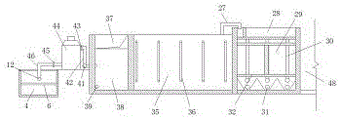
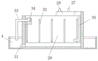
图中:1、圆形循环水池;2、固液分离排水管;201、固液分离器集污槽;202、排水管道;203、排污接管;204、滤板;205、上插管;3、排水井;4、管道排水沟;5、排污口;6、回水支架;7、盖板;8、回水支管;9、水池排沫管;10、供水阀门;11、供水支管;12、供水主管;13、回水主管;14、排污管道;15、边侧插管;16、分离池进水渠;17、涡流式分离池;18、分离池排污管;19、分离池排污管法兰接口;20、分离池出水渠;21、弧形筛缓冲布水池;22、弧形筛安装槽;23、弧形筛连通孔;24、弧形筛集污排污槽;25、弧形筛出水管;26、回水调节缓冲池;27、潜水泵;28、第一级生物滤池进水配水槽;29、第一级生物滤池;30、第一级生物滤池进水配水管;31、集污排污管;32、第一级生物滤池弹性生物滤料支撑;33、第一级生物滤池集沫排沫管;34、生物滤池连接口;35、第二级生物滤池;36、第二生物滤池弹性生物滤料支撑;37、紫外线消毒井;38、循环水出水井;39、平衡连通管;40、排空管;41、循环水出水管;42、蛋白质分离器进水管;43、蛋白质分离器进水控制阀门;44、蛋白质分离器;45、蛋白质分离器出水控制阀门;46、蛋白质分离器出水管;47、循环水绕过管;48、蓄水池;49、蓄水池出水和排空法兰接口。In the figure: 1. Circular circulating pool; 2. Drainage pipe for solid-liquid separation; 201. Sewage collection tank for solid-liquid separator; 202. Drainage pipe; 203. , drainage well; 4, pipeline drainage ditch; 5, sewage outlet; 6, return water bracket; 7, cover plate; 8, return water branch pipe; 9, pool foam discharge pipe; 10, water supply valve; 11, water supply branch pipe; 12 , water supply main pipe; 13, return water main pipe; 14, sewage pipe; 15, side intubation; 16, separation tank inlet channel; 17, vortex separation tank; 18, separation tank sewage pipe; 19, separation tank sewage pipe method Lan interface; 20. Separation tank outlet channel; 21. Curved screen buffer distribution pool; 22. Curved screen installation slot; 23. Curved screen connecting hole; 24. Curved screen sewage collection tank; 25. Curved screen Outlet pipe; 26, backwater adjustment buffer tank; 27, submersible pump; 28, first-stage biological filter inlet water distribution tank; 29, first-stage biological filter; 30, first-stage biological filter inlet
具体实施方式Detailed ways
下面将结合本实用新型实施例中的附图,对本实用新型实施例中的技术方案进行清楚、完整地描述,显然,所描述的实施例仅仅是本实用新型一部分实施例,而不是全部的实施例。基于本实用新型中的实施例,本领域普通技术人员在没有做出创造性劳动前提下所获得的所有其他实施例,都属于本实用新型保护的范围。The technical solutions in the embodiments of the present utility model will be clearly and completely described below with reference to the accompanying drawings in the embodiments of the present utility model. Obviously, the described embodiments are only a part of the embodiments of the present utility model, rather than all the implementations. example. Based on the embodiments of the present invention, all other embodiments obtained by those of ordinary skill in the art without creative work fall within the protection scope of the present invention.
请参阅图1-9,本实用新型提供一种技术方案:一种水产品循环水培养实验室养殖装置,包括圆形循环水池1、固液分离排水管2、固液分离器集污槽201、排水管道202、排污接管203、滤板204、上插管205、排水井3、管道排水沟4、排污口5、回水支架6、盖板7、回水支管8、水池排沫管9、供水阀门10、供水支管11、供水主管12、回水主管13、排污管道14、边侧插管15、分离池进水渠16、涡流式分离池17、分离池排污管18、分离池排污管法兰接口19、分离池出水渠20、弧形筛缓冲布水池21、弧形筛安装槽22、弧形筛连通孔23、弧形筛集污排污槽24、弧形筛出水管25、回水调节缓冲池26、潜水泵27、第一级生物滤池进水配水槽28、第一级生物滤池29、第一级生物滤池进水配水管30、集污排污管31、第一级生物滤池弹性生物滤料支撑32、第一级生物滤池集沫排沫管33、生物滤池连接口34、第二级生物滤池35、第二生物滤池弹性生物滤料支撑36、紫外线消毒井37、循环水出水井38、平衡连通管39、排空管40、循环水出水管41、蛋白质分离器进水管42、蛋白质分离器进水控制阀门43、蛋白质分离器44、蛋白质分离器出水控制阀门45、蛋白质分离器出水管46、循环水绕过管47、蓄水池48和蓄水池出水和排空法兰接口49,圆形循环水池1的底部固定安装有固液分离排水管2,且固液分离排水管2的下端管道安装于排水井3内,并且排水井3的边侧设置有管道排水沟4,而且管道排水沟4和排水井3之间预留有排污口5,管道排水沟4的内部固定有回水支架6,且管道排水沟4的顶部安装有盖板7,固液分离排水管2位于排水井3内的端部连接有回水支管8,且回水支管8与水池排沫管9相互连接,并且水池排沫管9的另一端设置于圆形循环水池1中,圆形循环水池1的内部设置有供水阀门10,且供水阀门10的端部连接有供水支管11,并且供水支管11上连接有供水主管12,而且供水主管12通过回水支架6设置于管道排水沟4内,同时供水主管12边侧的回水支管8上连接有回水主管13,固液分离排水管2的底部设置有排污管道14,且排污管道14的端部位于排水井3中,并且排污管道14的顶部设置有边侧插管15,分离池进水渠16设置于涡流式分离池17上,且分离池进水渠16与回水主管13的端部相互连接,并且涡流式分离池17的底部固定有分离池排污管18,而且分离池排污管18和管道排水沟4的内部之间连接有分离池排污管法兰接口19,同时涡流式分离池17的顶部设置有分离池出水渠20,弧形筛缓冲布水池21位于涡流式分离池17的边侧,且弧形筛缓冲布水池21的内部设置有弧形筛安装槽22、弧形筛连通孔23和弧形筛集污排污槽24,并且弧形筛缓冲布水池21的底部通过弧形筛出水管25与回水调节缓冲池26的内部贯通连接,而且回水调节缓冲池26中设置有潜水泵27,潜水泵27的管端位于第一级生物滤池进水配水槽28中,且第一级生物滤池进水配水槽28的底部设置有第一级生物滤池29,并且第一级生物滤池29的内部安装有第一级生物滤池进水配水管30,而且第一级生物滤池29的底部贯通连接有集污排污管31,同时第一级生物滤池29中固定有第一级生物滤池弹性生物滤料支撑32,第一级生物滤池集沫排沫管33设置于第一级生物滤池29的边侧,且第一级生物滤池29与第一级生物滤池集沫排沫管33管口位置处设置有生物滤池连接口34,并且第一级生物滤池集沫排沫管33的另一端设置于管道排水沟4中,第二级生物滤池35位于第一级生物滤池29的另一侧,且第二级生物滤池35内安装有第二生物滤池弹性生物滤料支撑36,并且第二级生物滤池35的边侧设置有循环水出水井38,循环水出水井38通过紫外线消毒井37与第二级生物滤池35的内部相互连接,且循环水出水井38的底部设置有平衡连通管39,并且第二级生物滤池35与紫外线消毒井37和管道排水沟4之间均安装有排空管40,循环水出水井38的内部通过循环水出水管41和蛋白质分离器进水管42与蛋白质分离器44相互连接,且蛋白质分离器进水管42上安装有蛋白质分离器进水控制阀门43,并且蛋白质分离器44通过蛋白质分离器出水控制阀门45连接有蛋白质分离器出水管46,而且蛋白质分离器出水管46的端部与供水主管12相互连接,同时供水主管12的底部设置有循环水绕过管47,蓄水池48位于管道排水沟4的上方,且蓄水池48和管道排水沟4之间通过蓄水池出水和排空法兰接口49相互连接。Please refer to Figures 1-9, the present utility model provides a technical solution: a laboratory culturing device for aquatic product circulating water culture, comprising a circular circulating water tank 1, a solid-liquid separation drain pipe 2, and a solid-liquid separator sewage collection tank 201 , drainage pipe 202, sewage pipe 203, filter plate 204, upper intubation pipe 205, drainage well 3, pipeline drainage ditch 4, sewage outlet 5, return water support 6, cover plate 7, return water branch pipe 8, pool foam discharge pipe 9 , water supply valve 10, water supply branch pipe 11, water supply main pipe 12, return water main pipe 13, sewage pipe 14, side intubation pipe 15, separation tank inlet channel 16, vortex separation tank 17, separation tank sewage pipe 18, separation tank sewage pipe Flange interface 19, separation tank outlet channel 20, curved screen buffer distribution pool 21, curved screen installation groove 22, curved screen connecting hole 23, curved screen sewage collection and sewage tank 24, curved screen water outlet pipe 25, return Water conditioning buffer tank 26, submersible pump 27, first-stage biological filter inlet water distribution tank 28, first-stage biological filter 29, first-stage biological filter inlet water distribution pipe 30, sewage collection and sewage pipe 31, first The first-stage biological filter elastic biological filter material support 32, the first-stage biological filter foam collecting and foaming pipe 33, the biological filter connecting port 34, the second-stage biological filter 35, the second biological filter elastic biological filter material support 36 , UV disinfection well 37, circulating water outlet well 38, balance communication pipe 39, emptying pipe 40, circulating water outlet pipe 41, protein skimmer inlet pipe 42, protein skimmer inlet control valve 43, protein skimmer 44, protein skimmer Separator outlet water control valve 45, protein separator outlet pipe 46, circulating water bypass pipe 47, reservoir 48 and reservoir outlet and emptying flange interface 49, the bottom of the circular circulating water tank 1 is fixedly installed with solid-liquid The drainage pipe 2 is separated, and the lower end pipe of the solid-liquid separation drainage pipe 2 is installed in the drainage well 3, and the side of the drainage well 3 is provided with a pipeline drainage ditch 4, and there is reserved space between the pipeline drainage ditch 4 and the drainage well 3. Sewage outlet 5, a
圆形循环水池1与管道排水沟4、涡流式分离池17、弧形筛缓冲布水池21、回水调节缓冲池26、第一级生物滤池29、第二级生物滤池35、紫外线消毒井37、循环水出水井38和蓄水池48共同组成水产品养殖的水循环利用系统,且圆形循环水池1的底部为向中倾斜的内凹状,方便杂质和分离和水源的循环净化,进行水产品的培育养殖。
固液分离排水管2由固液分离器集污槽201、排水管道202、排污接管203、滤板204和上插管205五部分组成,且固液分离器集污槽201的中部固定连接有排水管道202,并且固液分离器集污槽201的下方设置有排污接管203,而且排污接管203上安装有滤板204,同时排水管道202的顶部安装有上插管205,方便固液分离排水管2的组装使用。The solid-liquid
固液分离器集污槽201和排水管道202均设置为环形结构,且固液分离器集污槽201和滤板204设置为卡合的拆卸安装结构,并且滤板204上的孔径为10-25mm之间,上插管205和排水管道202之间构成密封环连接的拆卸安装结构,且上插管205远离排水管道202的一端设置为环形镂空状的封堵结构,并且上插管205上的环形镂空的直径为160mm,方便进行水的循环回收以及杂质的排污清理。The solid-liquid separator
边侧插管15与排污管道14的端部之间为贯穿的相互垂直设置,且边侧插管15和排污管道14之间为拆卸安装结构设置,并且边侧插管15和排污管道14的连接处为密封环连接,通过边侧插管15的长度改变进行圆形循环水池1中水源溢流量的控制改变。The
弧形筛缓冲布水池21内的弧形筛的弧长和幅宽选用均为1000mm,且弧形筛缓冲布水池21内的弧形筛的涩面朝上,并且每个弧形筛缓冲布水池21设置有3张弧形筛,方便弧形筛的安装,有效的滤去水中的颗粒杂质,节水、节能和绿色无公害、减少废水的排放,提高经济效率。The arc length and width of the arc screen in the arc screen
第一级生物滤池进水配水管30在第一级生物滤池29的内部等间距均匀分布,且第一级生物滤池29的水流方向为下进上出,底部设曝气盘,曝气盘安装方式为向上曝气,第一级生物滤池弹性生物滤料支撑32和第二生物滤池弹性生物滤料支撑36为形状相同、大小相等的“工”字型结构,且第一级生物滤池弹性生物滤料支撑32和第二生物滤池弹性生物滤料支撑36与第一级生物滤池29和第二级生物滤池35的侧壁之间为贯穿连接,并且第一级生物滤池弹性生物滤料支撑32和第二生物滤池弹性生物滤料支撑36与第一级生物滤池29和第二级生物滤池35的底部之间留有间距,而且第二级生物滤池35的水流方向为下进上出,底部设曝气盘,曝气盘安装方式为向下曝气,将污泥转化为生物附着载体,这样大大的提高了生物滤料的比表面积,提高了生物净化的效率,生物滤池无需进行排污操作,节省了循环水的消耗和劳动强度。The first-stage biological filter water inlet and
工作原理:在使用该水产品循环水培养实验室养殖装置时,首先根据图1-3,在圆形循环水池1中养殖的水和鱼儿及排泄物在固液分离排水管2的作用下进行分离,固液分离器集污槽201进行排泄物的收集,在排污接管203的作用下通过排污管道14排放到管道排水沟4内部,同理排污管道14上安装的边侧插管15控制圆形循环水池1内水的溢流量,在滤板204的作用下能够防止育苗一起冲走,在上插管205和排水管道202的贯通连接作用下,水和部分杂质进入回水支管8内,杂质在重力作用下进入排水井3和管道排水沟4内,然后其余的水在回水主管13的作用下进入循环流通;Working principle: When using the aquatic product circulating water culture laboratory breeding device, first according to Figure 1-3, the water, fish and excrement cultured in the circular circulating
如图4-9所示,水首先通过分离池进水渠16进入涡流式分离池17内,在涡流式分离池17中进入杂质和水的分离,排出部分杂质,随后杂质通过分离池排污管18和分离池排污管法兰接口19流入管道排水沟4的内部,同时涡流式分离池17中分离的水通过分离池出水渠20流入弧形筛缓冲布水池21中进行弧形筛的固液分离,在弧形筛安装槽22的作用下进行弧形筛的安装,过滤后的固定杂质在弧形筛集污排污槽24作用下排放,同时过滤后的水通过弧形筛出水管25进入回水调节缓冲池26内,然后在回水调节缓冲池26中的潜水泵27作用下导入第一级生物滤池进水配水槽28中,通过第一级生物滤池进水配水管30进入第一级生物滤池29中,在第一级生物滤池29中进行生物净化,同时在第一级生物滤池29的底部集污排污管31进行固态杂质的分离排放,第一级生物滤池弹性生物滤料支撑32的设置便于弹性生物滤料的放置安装,随后水在生物滤池连接口34和连接管道的作用下导入第二级生物滤池35中,在第二级生物滤池35的内部进行无淤泥生物净化,第二级生物滤池35和第一级生物滤池29设置有连接管道和鼓风机,提高净化效果,第二级生物滤池35中的水通过紫外线消毒井37导入循环水出水井38,在紫外线消毒井37中进行微生物的消毒操作,在循环水出水井38和平衡连通管39的进行充氧及充氧ORP控制,然后在蛋白质分离器44将循环水出水井38中的水依次通过循环水出水管41、蛋白质分离器进水管42与蛋白质分离器进水控制阀门43和蛋白质分离器出水控制阀门45与蛋白质分离器出水管46进行水质终端优化,然后在蛋白质分离器出水管46连接供水主管12,通过循环水绕过管47和供水主管12及供水阀门10排入到圆形循环水池1内,进行水源的循环流通,文中排沫管的使用,去除水中的悬浮泡沫杂质。As shown in Figures 4-9, the water first enters the vortex separation tank 17 through the separation
尽管参照前述实施例对本实用新型进行了详细的说明,对于本领域的技术人员来说,其依然可以对前述各实施例所记载的技术方案进行修改,或者对其中部分技术特征进行等同替换,凡在本实用新型的精神和原则之内,所作的任何修改、等同替换、改进等,均应包含在本实用新型的保护范围之内。Although the present invention has been described in detail with reference to the foregoing embodiments, for those skilled in the art, it is still possible to modify the technical solutions described in the foregoing embodiments, or perform equivalent replacements for some of the technical features. Within the spirit and principle of the present utility model, any modifications, equivalent replacements, improvements, etc. made shall be included within the protection scope of the present utility model.
Claims (8)
Priority Applications (1)
| Application Number | Priority Date | Filing Date | Title |
|---|---|---|---|
| CN201920916589.8U CN210094382U (en) | 2019-06-18 | 2019-06-18 | An aquatic product circulating water culture laboratory breeding device |
Applications Claiming Priority (1)
| Application Number | Priority Date | Filing Date | Title |
|---|---|---|---|
| CN201920916589.8U CN210094382U (en) | 2019-06-18 | 2019-06-18 | An aquatic product circulating water culture laboratory breeding device |
Publications (1)
| Publication Number | Publication Date |
|---|---|
| CN210094382U true CN210094382U (en) | 2020-02-21 |
Family
ID=69565468
Family Applications (1)
| Application Number | Title | Priority Date | Filing Date |
|---|---|---|---|
| CN201920916589.8U Expired - Fee Related CN210094382U (en) | 2019-06-18 | 2019-06-18 | An aquatic product circulating water culture laboratory breeding device |
Country Status (1)
| Country | Link |
|---|---|
| CN (1) | CN210094382U (en) |
Cited By (1)
| Publication number | Priority date | Publication date | Assignee | Title |
|---|---|---|---|---|
| CN110089479A (en) * | 2019-06-18 | 2019-08-06 | 岭南师范学院 | A kind of aquatic products recirculated water culture Laboratory culture device |
-
2019
- 2019-06-18 CN CN201920916589.8U patent/CN210094382U/en not_active Expired - Fee Related
Cited By (2)
| Publication number | Priority date | Publication date | Assignee | Title |
|---|---|---|---|---|
| CN110089479A (en) * | 2019-06-18 | 2019-08-06 | 岭南师范学院 | A kind of aquatic products recirculated water culture Laboratory culture device |
| CN110089479B (en) * | 2019-06-18 | 2024-04-12 | 岭南师范学院 | Aquatic product circulating water culture laboratory breeding device |
Similar Documents
| Publication | Publication Date | Title |
|---|---|---|
| CN204070180U (en) | A kind of cycle water fiberglass aquarium system | |
| CN105613389B (en) | A kind of shrimp ecosystem | |
| CN110192538A (en) | A kind of external Penaeus Vannmei circulating water culture system | |
| CN104904628B (en) | A kind of fry hatching breeding system | |
| CN109924151A (en) | A kind of device for culturing prawn and method of continuous concentration blowdown | |
| CN106698849B (en) | Distributed treatment and recycling system and method for wastewater of milking parlour of large-scale dairy farm | |
| CN104756916A (en) | Self-maintaining reflowing type cold water salmon fry culture system | |
| CN108094301A (en) | A kind of circulating water culture system and application method based on the processing of biological flocculation dystopy | |
| CN205061704U (en) | Floated microorganism sewage purification ware in aquatic | |
| CN204599025U (en) | A kind of water-saving type flowing water culture pond | |
| CN110089479B (en) | Aquatic product circulating water culture laboratory breeding device | |
| CN206570083U (en) | Floatation type microorganism water body purification system | |
| CN208394902U (en) | A kind of floating media filter | |
| CN203451340U (en) | Reclaimed water treatment device in FBMBR (Fluidized Bed Membrane Bioreactor) | |
| CN109937949A (en) | Flowing water circulation fish farming system | |
| CN213463479U (en) | An intelligent aquaculture pond | |
| CN205455358U (en) | Penaeus cultivation system | |
| CN217958365U (en) | Industrial aquaculture pond | |
| CN220265504U (en) | Novel aquaculture is exempted from to wash filtration system | |
| CN105000758A (en) | Integrated membrane bioreactor | |
| CN201648191U (en) | Mobile flat membrane MBR sewage treatment equipment | |
| CN112715463A (en) | Low-power-consumption energy-saving recirculating aquaculture system | |
| CN209493375U (en) | A kind of domestic sewage processing system | |
| CN208071427U (en) | Low energy consumption is from reflow type membrane bioreactor | |
| CN207769563U (en) | A kind of plate film assembly |
Legal Events
| Date | Code | Title | Description |
|---|---|---|---|
| GR01 | Patent grant | ||
| GR01 | Patent grant | ||
| CF01 | Termination of patent right due to non-payment of annual fee |
Granted publication date: 20200221 Termination date: 20200618 |
|
| CF01 | Termination of patent right due to non-payment of annual fee |