CN210082165U - Waste plastic recycling device - Google Patents
Waste plastic recycling device Download PDFInfo
- Publication number
- CN210082165U CN210082165U CN201920576936.7U CN201920576936U CN210082165U CN 210082165 U CN210082165 U CN 210082165U CN 201920576936 U CN201920576936 U CN 201920576936U CN 210082165 U CN210082165 U CN 210082165U
- Authority
- CN
- China
- Prior art keywords
- tube
- shell
- outlet
- nozzle
- feeding hopper
- Prior art date
- Legal status (The legal status is an assumption and is not a legal conclusion. Google has not performed a legal analysis and makes no representation as to the accuracy of the status listed.)
- Expired - Fee Related
Links
Images


Landscapes
- Separation, Recovery Or Treatment Of Waste Materials Containing Plastics (AREA)
- Processing And Handling Of Plastics And Other Materials For Molding In General (AREA)
Abstract
废弃塑料回收装置,包括粉碎融化机构、塑料挤出机、出料冷却机构及切断机构;粉碎融化机构、塑料挤出机及出料冷却机构依次连通;切断机构设在出料冷却机构的出料端处,以切断出料冷却机构排出的连续条状塑料。本实用新型实现了废弃塑料的回收利用,从进料斗投入废弃塑料,便可从喷嘴输出颗粒状固体塑料,输出的颗粒状固体塑料可直接作为工业生产或3D打印的原材料。
The waste plastic recycling device includes a crushing and melting mechanism, a plastic extruder, a discharging cooling mechanism and a cutting mechanism; the crushing and melting mechanism, the plastic extruder and the discharging cooling mechanism are connected in sequence; the cutting mechanism is arranged at the discharging of the discharging cooling mechanism at the end to cut off the continuous strip of plastic discharged from the discharge cooling mechanism. The utility model realizes the recycling of waste plastics, and the waste plastics are put into the feeding hopper, and the granular solid plastics can be output from the nozzle, and the output granular solid plastics can be directly used as raw materials for industrial production or 3D printing.
Description
技术领域technical field
本实用新型涉及垃圾回收机械领域,特别是一种废弃塑料回收装置。The utility model relates to the field of garbage recycling machinery, in particular to a waste plastic recycling device.
背景技术Background technique
随着经济的发展和人民生活水平的提高,垃圾的产出量也越来越高,如何有效回收利用垃圾已经成为了社会越来越关注的问题。With the development of the economy and the improvement of people's living standards, the output of garbage is also getting higher and higher. How to effectively recycle garbage has become a problem that the society pays more and more attention to.
其中,不可降解的塑料是组成垃圾最主要的成分,而塑料废弃品在自然条件下不容易被分解,所产生的白色污染已经成为全球性的公害,对生态环境造成了严重的影响。Among them, non-degradable plastic is the most important component of garbage, and plastic waste is not easy to be decomposed under natural conditions, and the resulting white pollution has become a global public hazard, which has a serious impact on the ecological environment.
传统的压缩深埋地下的处理方式占用空间较大,降解速度缓慢,回收利用率为零,已经不能满足日益增长的废弃塑料垃圾量的处理需求。The traditional method of compression and deep burial takes up a lot of space, the degradation speed is slow, and the recycling rate is zero, which can no longer meet the processing needs of the growing amount of waste plastic waste.
发明内容SUMMARY OF THE INVENTION
本实用新型的目的是克服现有技术的不足,而提供一种废弃塑料回收装置,它解决了传统的废弃塑料垃圾回收利用难的问题,它以废弃塑料做为原材料,可产出符合工业应用的颗粒状塑料原料。The purpose of the utility model is to overcome the deficiencies of the prior art, and provide a waste plastic recycling device, which solves the problem of the difficulty of recycling and utilization of traditional waste plastic waste. granular plastic raw materials.
本实用新型的技术方案是:废弃塑料回收装置,包括粉碎融化机构、塑料挤出机、出料冷却机构及切断机构;粉碎融化机构、塑料挤出机及出料冷却机构依次连通;切断机构设在出料冷却机构的出料端处,以切断出料冷却机构排出的连续条状塑料。The technical scheme of the utility model is as follows: a waste plastic recycling device includes a crushing and melting mechanism, a plastic extruder, a discharging cooling mechanism and a cutting mechanism; the crushing and melting mechanism, the plastic extruder and the discharging cooling mechanism are connected in sequence; the cutting mechanism is provided with At the discharge end of the discharge cooling mechanism, the continuous strip-shaped plastic discharged from the discharge cooling mechanism is cut off.
本实用新型进一步的技术方案是:粉碎融化机构包括进料斗、破碎滚筒组、驱动组件和电热板;进料斗上端设有进料口,下端设有出料口,进料斗在内腔下端靠近出料口处设有用于过滤杂质的筛板;破碎滚筒组包括两个滚筒,滚筒外壁上均布有多个钉齿,两个滚筒分别通过转轴安装在进料斗的内腔中,两个滚筒之间设有条形间隙;驱动组件设在进料斗外并与两个滚筒的转轴关联,以驱动两个滚筒同步反向转动;电热板倾斜设在进料斗的内腔中,并位于破碎滚筒组的下端,其与进料斗的内腔之间形成下落口。The further technical scheme of the utility model is as follows: the crushing and melting mechanism includes a feeding hopper, a crushing roller group, a driving component and an electric heating plate; the upper end of the feeding hopper is provided with a feeding port, the lower end is provided with a discharging port, and the feeding hopper has an inner cavity The lower end is provided with a sieve plate for filtering impurities; the crushing drum group includes two drums, and the outer wall of the drum is evenly distributed with a plurality of nail teeth, and the two drums are respectively installed in the inner cavity of the feeding hopper through the rotating shaft. There is a strip gap between the two rollers; the driving component is arranged outside the feeding hopper and is associated with the rotating shafts of the two rollers to drive the two rollers to rotate synchronously and reversely; the electric heating plate is inclined and arranged in the inner cavity of the feeding hopper , and is located at the lower end of the crushing drum group, and a drop opening is formed between it and the inner cavity of the feeding hopper.
本实用新型再进一步的技术方案是:驱动组件包括电机A、齿轮A及齿轮B;电机A安装在进料斗的外壁上,并通过联轴器与滚筒的转轴连接;齿轮A和齿轮B分别安装在两个滚筒的转轴上,且相互啮合。A further technical solution of the present utility model is: the driving component includes a motor A, a gear A and a gear B; the motor A is installed on the outer wall of the feeding hopper, and is connected with the rotating shaft of the drum through a coupling; the gear A and the gear B are respectively It is installed on the rotating shaft of the two rollers and meshes with each other.
本实用新型更进一步的技术方案是:出料冷却机构包括管壳式换热器、水泵、水箱、喷嘴及冷却管;管壳式换热器内设有互不连通的管程腔体和壳程腔体,管程腔体在管壳式换热器外壁上设有管程入口和管程出口,壳程腔体在管壳式换热器外壁上设有冷却液入口和冷却液出口;水泵一端为进水端,另一端为出水端;水箱外壁上设有连通至其内腔的进水口和出水口,进水口与管壳式换热器的管程出口连通,出水口与水泵的进水端连通;喷嘴呈两端开口的管形,其一端为进料端,另一端为出料端;冷却管螺旋盘绕在喷嘴上,其两端分别与管壳式换热器的管程入口及水泵的出水端连通。A further technical solution of the utility model is: the discharge cooling mechanism includes a shell-and-tube heat exchanger, a water pump, a water tank, a nozzle and a cooling pipe; the shell-and-tube heat exchanger is provided with a tube-side cavity and a shell that are not connected to each other. The tube-side cavity is provided with a tube-side inlet and a tube-side outlet on the outer wall of the shell-and-tube heat exchanger, and the shell-side cavity is provided with a cooling liquid inlet and a cooling liquid outlet on the outer wall of the shell-and-tube heat exchanger; One end of the water pump is the water inlet end, and the other end is the water outlet end; the outer wall of the water tank is provided with a water inlet and a water outlet connected to its inner cavity, the water inlet is connected with the tube side outlet of the shell-and-tube heat exchanger, and the water outlet is connected to the water outlet of the pump. The water inlet end is connected; the nozzle is in the shape of a tube with two open ends, one end of which is the feeding end and the other end is the discharging end; the cooling pipe is spirally wound on the nozzle, and its two ends are respectively connected to the tube side of the shell and tube heat exchanger. The inlet is communicated with the outlet end of the water pump.
本实用新型更进一步的技术方案是:出料冷却机构还包括设在喷嘴两侧相对布置的冷却风扇。A further technical solution of the utility model is that the discharging cooling mechanism further comprises cooling fans arranged oppositely on both sides of the nozzle.
本实用新型更进一步的技术方案是:塑料挤出机一端设有进口,另一端设有出口,塑料挤出机的进口与进料斗的出料口连通,塑料挤出机的出口与喷嘴的进料端连通。The further technical scheme of the utility model is: one end of the plastic extruder is provided with an inlet, the other end is provided with an outlet, the inlet of the plastic extruder is communicated with the discharge port of the feeding hopper, and the outlet of the plastic extruder is connected with the nozzle of the nozzle. The feed end is connected.
本实用新型更进一步的技术方案是:切断机构包括电机B和安装在电机B的机轴上的切刀,切刀正对喷嘴的出料端。A further technical solution of the present utility model is that the cutting mechanism comprises a motor B and a cutter installed on the shaft of the motor B, and the cutter is facing the discharge end of the nozzle.
本实用新型与现有技术相比具有如下优点:Compared with the prior art, the utility model has the following advantages:
1、实现了废弃塑料的回收利用,从进料斗投入废弃塑料,便可从喷嘴输出颗粒状固体塑料,输出的颗粒状固体塑料可直接作为工业生产或3D打印的原材料。1. The recycling of waste plastics is realized, and the waste plastics are put into the feed hopper, and granular solid plastics can be output from the nozzle, and the output granular solid plastics can be directly used as raw materials for industrial production or 3D printing.
2、通过调节切刀转速、塑料挤出机的挤出速率、或更换不同内径的喷嘴即可输出不同尺寸的颗粒状固体塑料,以适应不同应用场景的工业生产或3D打印原材料需求。2. Granular solid plastics of different sizes can be output by adjusting the rotational speed of the cutter, the extrusion rate of the plastic extruder, or by changing nozzles with different inner diameters to meet the needs of industrial production or 3D printing raw materials in different application scenarios.
以下结合图和实施例对本实用新型作进一步描述。The utility model will be further described below in conjunction with figures and embodiments.
附图说明Description of drawings
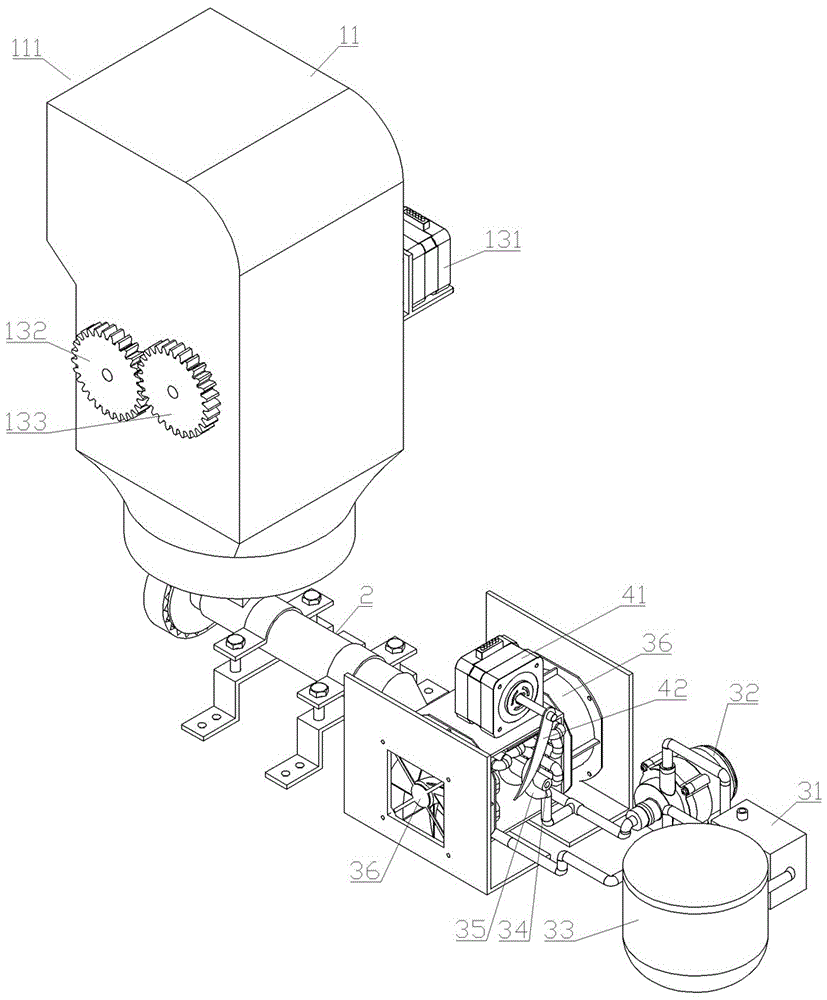
图1为本实用新型的结构示意图;Fig. 1 is the structural representation of the utility model;
图2为粉碎融化机构的结构示意图;Fig. 2 is the structural representation of pulverizing and melting mechanism;
图3为出料冷却机构的连接关系示意图。Figure 3 is a schematic diagram of the connection relationship of the discharge cooling mechanism.
具体实施方式Detailed ways
实施例1:Example 1:
如图1-3所示,废弃塑料回收装置,包括粉碎融化机构、塑料挤出机2、出料冷却机构及切断机构。As shown in Figure 1-3, the waste plastic recycling device includes a crushing and melting mechanism, a plastic extruder 2, a discharge cooling mechanism and a cutting mechanism.
粉碎融化机构包括进料斗11、破碎滚筒组、驱动组件和电热板14。进料斗11上端设有进料口111,下端设有出料口112,进料斗11在内腔下端靠近出料口112处设有用于过滤杂质的筛板113。破碎滚筒组包括两个滚筒121,滚筒121外壁上均布有多个钉齿1211,两个滚筒121分别通过转轴122安装在进料斗11的内腔中,两个滚筒121之间设有条形间隙15,条形间隙15可供碾碎的塑料通过并下落。驱动组件设在进料斗11外并与两个滚筒121的转轴122关联,以驱动两个滚筒121同步反向转动,驱动组件包括电机A131、齿轮A132及齿轮B133,电机A131安装在进料斗11的外壁上,并通过联轴器与滚筒121的转轴122连接,齿轮A132和齿轮B133分别安装在两个滚筒121的转轴122上,且相互啮合。电热板14倾斜设在进料斗11的内腔中,并位于破碎滚筒组的下端,其与进料斗11的内腔之间形成下落口16。The crushing and melting mechanism includes a
出料冷却机构包括管壳式换热器31、水泵32、水箱33、喷嘴34及冷却管35。管壳式换热器31内设有互不连通的管程腔体和壳程腔体,管程腔体在管壳式换热器31外壁上设有管程入口311和管程出口312,壳程腔体在管壳式换热器31外壁上设有冷却液入口313和冷却液出口314。水泵32一端为进水端,另一端为出水端。水箱33外壁上设有连通至其内腔的进水口331和出水口332,进水口331与管壳式换热器31的管程出口312连通,出水口332与水泵32的进水端连通。喷嘴34呈两端开口的管形,其一端为进料端,另一端为出料端。冷却管35螺旋盘绕在喷嘴34上,其两端分别与管壳式换热器31的管程入口311及水泵32的出水端连通。The discharge cooling mechanism includes a shell and
塑料挤出机2一端设有进口,另一端设有出口,塑料挤出机2的进口与进料斗11的出料口112连通,塑料挤出机2的出口与喷嘴34的进料端连通。One end of the plastic extruder 2 is provided with an inlet, and the other end is provided with an outlet. The inlet of the plastic extruder 2 is communicated with the
切断机构包括电机B41和安装在电机B41的机轴上的切刀42,切刀42正对喷嘴34的出料端,电机B41驱动切刀42做回转运动,以切断喷嘴34的出料端排出的连续条状塑料。The cutting mechanism includes a motor B41 and a
优选,出料冷却机构还包括设在喷嘴34两侧相对布置的冷却风扇36。Preferably, the discharge cooling mechanism further includes
简述本实用新型的工作过程:Briefly describe the working process of the present utility model:
回收废弃塑料之前,先进行以下几项操作:Before recycling waste plastic, do the following:
a、启动电热板14,进行预热;a. Start the
b、启动电机A131,使破碎滚筒组的两个滚筒121同步反向转动;b. Start the motor A131 to make the two
c、为塑料挤出机2通电,使其待机;c. Power on the plastic extruder 2 to make it stand by;
d、启动水泵32,使冷却介质在冷却管35中流动;d. Start the
e、在管壳式换热器31的壳程腔体内通入冷却液,当冷却液填充满管壳式换热器31的壳程腔体后,保持从冷却液入口313输入的冷却液流量与冷却液出口314输出的冷却液流量一致;e. The cooling liquid is introduced into the shell side cavity of the shell and
f、启动电机B41,以驱动切刀42做回转运动。f. Start the motor B41 to drive the
1、将废弃塑料从进料斗11上端的进料口111投入进料斗11的内腔中,废弃塑料被同步反向转动的两个滚筒121碾碎,并从两个滚筒121之间的条形缝隙下落在电热板上,碾碎的废弃塑料在电热板14上被加热至融化,融化塑料顺着电热板14的斜度从下落口16处滴落,通过筛板113后,从出料口112排出。1. Put the waste plastic into the inner cavity of the
2、从进料斗11的出料口112排出的融化塑料通过塑料挤出机2进口进入塑料挤出机2内腔中,然后通过推挤从塑料挤出机2出口排出。2. The melted plastic discharged from the
3、从塑料挤出机2出口排出的液态塑料通过喷嘴34进料端进入喷嘴34内腔,并在塑料挤出机2的推挤作用下向喷嘴34出料端移动,液态塑料在喷嘴34内腔中移动的过程中,通过冷却管35内循环流动的水不断被带走热量,从喷嘴34出料端排出时冷却硬化为固体。3. The liquid plastic discharged from the outlet of the plastic extruder 2 enters the inner cavity of the
4、从喷嘴34出料端排出的条状的固体塑料通过切刀42切断为颗粒状固体塑料。4. The strip-shaped solid plastic discharged from the discharge end of the
Claims (7)
Priority Applications (1)
| Application Number | Priority Date | Filing Date | Title |
|---|---|---|---|
| CN201920576936.7U CN210082165U (en) | 2019-04-25 | 2019-04-25 | Waste plastic recycling device |
Applications Claiming Priority (1)
| Application Number | Priority Date | Filing Date | Title |
|---|---|---|---|
| CN201920576936.7U CN210082165U (en) | 2019-04-25 | 2019-04-25 | Waste plastic recycling device |
Publications (1)
| Publication Number | Publication Date |
|---|---|
| CN210082165U true CN210082165U (en) | 2020-02-18 |
Family
ID=69475845
Family Applications (1)
| Application Number | Title | Priority Date | Filing Date |
|---|---|---|---|
| CN201920576936.7U Expired - Fee Related CN210082165U (en) | 2019-04-25 | 2019-04-25 | Waste plastic recycling device |
Country Status (1)
| Country | Link |
|---|---|
| CN (1) | CN210082165U (en) |
Cited By (1)
| Publication number | Priority date | Publication date | Assignee | Title |
|---|---|---|---|---|
| CN110053183A (en) * | 2019-04-25 | 2019-07-26 | 南华大学 | Waste plastic recyclable device and recovery method |
-
2019
- 2019-04-25 CN CN201920576936.7U patent/CN210082165U/en not_active Expired - Fee Related
Cited By (1)
| Publication number | Priority date | Publication date | Assignee | Title |
|---|---|---|---|---|
| CN110053183A (en) * | 2019-04-25 | 2019-07-26 | 南华大学 | Waste plastic recyclable device and recovery method |
Similar Documents
| Publication | Publication Date | Title |
|---|---|---|
| CN110238986A (en) | A high-efficiency plastic granulation device | |
| CN204566452U (en) | A kind of horizontal-type waste plastic reclaims comminutor | |
| CN210148474U (en) | A kind of waste recycling granulation device for polymer plastic film production | |
| CN206416474U (en) | A kind of PC pipe extruding production lines with cooler bin | |
| CN104859067A (en) | Horizontal plastic waste recovering granulator | |
| CN112720908B (en) | Hot air melting plastic extrusion granulator and use method thereof | |
| CN112454742A (en) | Environment-friendly waste plastic bottle treatment device | |
| CN201511459U (en) | Thin film air cooling granulator | |
| CN118721531A (en) | Granulating device and method for recycling waste plastics | |
| CN210132749U (en) | Cooling device for plastic extruder | |
| CN222135553U (en) | Waste plastic crushing, recycling and granulation device | |
| CN206623375U (en) | A kind of PVC material contaminant filter extruders of high-efficiency environment friendly | |
| CN110053183A (en) | Waste plastic recyclable device and recovery method | |
| CN211104989U (en) | Broken melting all-in-one of plastics | |
| CN106832396B (en) | Full-automatic plasticizing desulfurizing machine | |
| CN108515637A (en) | A kind of horizontal hot air melting waste plastic recovery pelletizer | |
| CN206123990U (en) | Be used for quick prilling granulator of PVC material | |
| CN217021364U (en) | Extruder with hybrid heating function | |
| CN216068600U (en) | Extrusion device is used in production of hot tectorial membrane of PET | |
| CN216578698U (en) | Plastic products secondary recycle device | |
| CN110843153A (en) | A plastic crushing and melting machine | |
| CN215512188U (en) | Extrusion molding device for recycling plastics | |
| CN116442420A (en) | A plastic production process | |
| CN204431693U (en) | Fixed star extruder | |
| CN210477762U (en) | PVC panel production is with heating extrusion equipment |
Legal Events
| Date | Code | Title | Description |
|---|---|---|---|
| GR01 | Patent grant | ||
| GR01 | Patent grant | ||
| CF01 | Termination of patent right due to non-payment of annual fee |
Granted publication date: 20200218 Termination date: 20210425 |
|
| CF01 | Termination of patent right due to non-payment of annual fee |