CN210068290U - Exhaust pipe decoration cover assembly with protection structure - Google Patents
Exhaust pipe decoration cover assembly with protection structure Download PDFInfo
- Publication number
- CN210068290U CN210068290U CN201920510618.0U CN201920510618U CN210068290U CN 210068290 U CN210068290 U CN 210068290U CN 201920510618 U CN201920510618 U CN 201920510618U CN 210068290 U CN210068290 U CN 210068290U
- Authority
- CN
- China
- Prior art keywords
- exhaust pipe
- spring
- connecting rod
- sleeve
- trim cover
- Prior art date
- Legal status (The legal status is an assumption and is not a legal conclusion. Google has not performed a legal analysis and makes no representation as to the accuracy of the status listed.)
- Active
Links
Images

Landscapes
- Exhaust Silencers (AREA)
Abstract
本实用新型公开了一种带有防护结构的排气管装饰罩总成,包括排气管和排气管装饰罩本体,所述排气管的外侧均匀设置有螺孔,所述连接环远离排气管的一侧安装有排气管装饰罩本体,所述第四弹簧远离排气管装饰罩本体的一端水平安装有固定环,所述第二套筒内部水平安装有第三弹簧,所述第三连接杆远离第三弹簧的一端通过第一铰接轴铰接有第二连接杆,所述金属板的外侧粘贴有橡胶垫,所述第二套筒两侧的排气管装饰罩本体侧壁均竖直安装有第一套筒,所述第二弹簧远离排气管装饰罩本体一端竖直安装有贯穿第一套筒的第一连接杆。该带有防护结构的排气管装饰罩总成通过第二弹簧、第三弹簧和第一弹簧的弹力作用提高该排气管装饰罩总成的防护效果。

The utility model discloses an exhaust pipe decoration cover assembly with a protective structure, which comprises an exhaust pipe and an exhaust pipe decoration cover body. The outer side of the exhaust pipe is evenly provided with screw holes, and the connecting ring is far away from the An exhaust pipe trim cover body is installed on one side of the exhaust pipe, a fixing ring is installed horizontally at one end of the fourth spring away from the exhaust pipe trim cover body, and a third spring is installed horizontally inside the second sleeve. One end of the third connecting rod away from the third spring is hinged with a second connecting rod through the first hinge shaft, rubber pads are pasted on the outside of the metal plate, and the exhaust pipe trim cover body side on both sides of the second sleeve A first sleeve is installed vertically on each wall, and a first connecting rod extending through the first sleeve is installed vertically at one end of the second spring away from the body of the exhaust pipe trim cover. The exhaust pipe trim cover assembly with the protective structure improves the protection effect of the exhaust pipe trim cover assembly through the elastic force of the second spring, the third spring and the first spring.
Description
技术领域technical field
本实用新型涉及排气管装饰罩总成技术领域,具体为一种带有防护结构的排气管装饰罩总成。The utility model relates to the technical field of an exhaust pipe decorative cover assembly, in particular to an exhaust pipe decorative cover assembly with a protective structure.
背景技术Background technique
排气管装饰罩总成是汽车尾气管尾部的部件,它具有保护尾气管的作用。The exhaust pipe trim cover assembly is a component at the tail of the automobile exhaust pipe, which has the function of protecting the exhaust pipe.
但目前市场上大多数排气管装饰罩总成防护效果不佳,并且目前市场上大多数排气管装饰罩总成不能适用于不同种类的汽车,为此我们提出了一种带有防护结构的排气管装饰罩总成来解决上述问题。However, most of the exhaust pipe trim cover assemblies on the market have poor protection effects, and most exhaust pipe trim cover assemblies on the market cannot be applied to different types of vehicles. For this reason, we propose a protective structure with The exhaust pipe trim cover assembly to solve the above problems.
实用新型内容Utility model content
本实用新型的目的在于提供一种带有防护结构的排气管装饰罩总成,以解决上述背景技术中提出的问题。The purpose of the present invention is to provide an exhaust pipe decorative cover assembly with a protective structure to solve the problems raised in the above background technology.
为实现上述目的,本实用新型提供如下技术方案:一种带有防护结构的排气管装饰罩总成,包括排气管和排气管装饰罩本体,所述排气管的外侧均匀设置有螺孔,且排气管通过螺孔和锁紧螺栓安装有连接环,所述连接环远离排气管的一侧安装有排气管装饰罩本体,且排气管装饰罩本体内部远离连接环的一端均匀竖直安装有第四弹簧,所述第四弹簧远离排气管装饰罩本体的一端水平安装有固定环,且排气管装饰罩本体外侧远离连接环的一端水平安装有第二套筒,所述第二套筒内部水平安装有第三弹簧,且第三弹簧两侧水平安装有贯穿第二套筒的第三连接杆,所述第三连接杆远离第三弹簧的一端通过第一铰接轴铰接有第二连接杆,且第二连接杆远离第三连接杆的一端通过第二铰接轴铰接有金属板,所述金属板的外侧粘贴有橡胶垫,且金属板内侧中间位置处均匀竖直安装有与第二套筒相连接的第一弹簧,所述第二套筒两侧的排气管装饰罩本体侧壁均竖直安装有第一套筒,且第一套筒的内部竖直安装有第二弹簧,所述第二弹簧远离排气管装饰罩本体一端竖直安装有贯穿第一套筒的第一连接杆,且第一连接杆远离第一套筒的一端与金属板相连接。In order to achieve the above purpose, the utility model provides the following technical solutions: an exhaust pipe decorative cover assembly with a protective structure, including an exhaust pipe and an exhaust pipe decorative cover body, the outer side of the exhaust pipe is evenly provided with screw holes, and the exhaust pipe is installed with a connecting ring through the screw holes and locking bolts, the side of the connecting ring away from the exhaust pipe is installed with an exhaust pipe trim cover body, and the interior of the exhaust pipe trim cover body is far away from the connecting ring A fourth spring is evenly and vertically installed at one end of the fourth spring, and a fixing ring is installed horizontally at one end of the fourth spring away from the body of the exhaust pipe decoration cover, and a second set of A third spring is installed horizontally inside the second sleeve, and a third connecting rod extending through the second sleeve is installed horizontally on both sides of the third spring, and the end of the third connecting rod away from the third spring passes through the A hinge shaft is hinged with a second connecting rod, and one end of the second connecting rod away from the third connecting rod is hinged with a metal plate through the second hinge shaft. The first spring connected to the second sleeve is evenly and vertically installed, the side walls of the exhaust pipe decorative cover body on both sides of the second sleeve are vertically installed with the first sleeve, and the first sleeve is installed vertically. A second spring is installed vertically inside, and one end of the second spring away from the body of the exhaust pipe trim cover is vertically installed with a first connecting rod penetrating the first sleeve, and one end of the first connecting rod away from the first sleeve is connected with the first connecting rod. The metal plates are connected.
优选的,所述第二连接杆通过第二铰接轴和金属板连接构成转动机构,且第二连接杆通过第一铰接轴和第三连接杆连接构成转动机构,并且第三连接杆通过第三弹簧和第二套筒连接构成伸缩机构。Preferably, the second connecting rod is connected by the second hinge shaft and the metal plate to form a rotating mechanism, and the second connecting rod is connected by the first hinge shaft and the third connecting rod to form a rotating mechanism, and the third connecting rod is connected by the third connecting rod. The spring and the second sleeve are connected to form a telescopic mechanism.
优选的,所述第一连接杆通过第二弹簧和第一套筒连接构成伸缩机构。Preferably, the first connecting rod is connected with the first sleeve through a second spring to form a telescopic mechanism.
优选的,所述金属板通过第一弹簧和第二套筒连接构成伸缩机构。Preferably, the metal plate is connected by a first spring and a second sleeve to form a telescopic mechanism.
优选的,所述固定环通过第四弹簧和排气管装饰罩本体连接构成伸缩机构。Preferably, the fixing ring is connected with the exhaust pipe trim cover body through a fourth spring to form a telescopic mechanism.
优选的,所述锁紧螺栓和螺孔之间为螺纹连接。Preferably, the locking bolt and the screw hole are connected by a thread.
与现有技术相比,本实用新型的有益效果是:Compared with the prior art, the beneficial effects of the present utility model are:
(1)通过安装有锁紧螺栓、螺孔、排气管、第四弹簧和固定环,先通过锁紧螺栓和螺孔将该带有防护结构的排气管装饰罩总成安装在排气管上,在第四弹簧的弹力作用下带动固定环自动与排气管紧密贴合,从而便于提高该带有防护结构的排气管装饰罩总成安装的稳定性;(1) By installing locking bolts, screw holes, exhaust pipe, fourth spring and fixing ring, first install the exhaust pipe trim cover assembly with protective structure on the exhaust through locking bolts and screw holes. On the pipe, under the elastic force of the fourth spring, the fixing ring is driven to closely fit the exhaust pipe automatically, so as to improve the installation stability of the exhaust pipe decorative cover assembly with a protective structure;
(2)同时装置通过安装有排气管、螺孔和锁紧螺栓,通过排气管表面均匀设置的螺孔与锁紧螺栓配合,从而便于该带有防护结构的排气管装饰罩总成满足不同车型的需要;(2) At the same time, the device is equipped with an exhaust pipe, screw holes and locking bolts, and the screw holes evenly arranged on the surface of the exhaust pipe are matched with the locking bolts, so as to facilitate the exhaust pipe decorative cover assembly with a protective structure Meet the needs of different models;
(3)同时装置通过安装有金属板、橡胶垫、第二连接杆、第一连接杆、第三连接杆、第二弹簧、第三弹簧和第一弹簧,当汽车受到颠簸从而使得金属板和橡胶垫与地面接触时,地面传递给金属板和橡胶垫的力分别传递给第二连接杆和第一连接杆,第二连接杆将力传递给第三连接杆,从而在第二弹簧、第三弹簧和第一弹簧的弹力作用下消除该力,从而便于提高该带有防护结构的排气管装饰罩总成的防护效果。(3) At the same time, the device is installed with a metal plate, a rubber pad, a second connecting rod, a first connecting rod, a third connecting rod, a second spring, a third spring and a first spring. When the car is bumped, the metal plate and the When the rubber pad is in contact with the ground, the force transmitted by the ground to the metal plate and the rubber pad is transmitted to the second connecting rod and the first connecting rod respectively, and the second connecting rod transmits the force to the third connecting rod, so that the second The force is eliminated under the elastic force of the three springs and the first spring, thereby facilitating the improvement of the protective effect of the exhaust pipe trim cover assembly with the protective structure.
附图说明Description of drawings
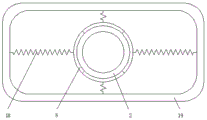
图1为本实用新型正视剖视结构示意图;Fig. 1 is the front view sectional structure schematic diagram of the present utility model;
图2为本实用新型右视结构示意图;Fig. 2 is the right side view structure schematic diagram of the present utility model;
图3为本实用新型俯视结构示意图。FIG. 3 is a schematic top view of the structure of the utility model.
图中:1、锁紧螺栓;2、排气管;3、螺孔;4、连接环;5、固定环;6、第一连接杆;7、第二连接杆;8、第三连接杆;9、第一弹簧;10、第一铰接轴;11、第二铰接轴;12、第一套筒;13、第二弹簧;14、橡胶垫;15、金属板;16、第三弹簧;17、第二套筒;18、第四弹簧;19、排气管装饰罩本体。In the figure: 1, locking bolt; 2, exhaust pipe; 3, screw hole; 4, connecting ring; 5, fixing ring; 6, first connecting rod; 7, second connecting rod; 8, third connecting
具体实施方式Detailed ways
下面将结合本实用新型实施例中的附图,对本实用新型实施例中的技术方案进行清楚、完整地描述,显然,所描述的实施例仅仅是本实用新型一部分实施例,而不是全部的实施例。基于本实用新型中的实施例,本领域普通技术人员在没有做出创造性劳动前提下所获得的所有其他实施例,都属于本实用新型保护的范围。The technical solutions in the embodiments of the present utility model will be clearly and completely described below with reference to the accompanying drawings in the embodiments of the present utility model. Obviously, the described embodiments are only a part of the embodiments of the present utility model, rather than all the implementations. example. Based on the embodiments of the present invention, all other embodiments obtained by those of ordinary skill in the art without creative work fall within the protection scope of the present invention.
请参阅图1-3,本实用新型提供的一种实施例:一种带有防护结构的排气管装饰罩总成,包括排气管2和排气管装饰罩本体19,排气管2的外侧均匀设置有螺孔3,且排气管2通过螺孔3和锁紧螺栓1安装有连接环4,锁紧螺栓1和螺孔3之间为螺纹连接,便于安装更换,连接环4远离排气管2的一侧安装有排气管装饰罩本体19,且排气管装饰罩本体19内部远离连接环4的一端均匀竖直安装有第四弹簧18,第四弹簧18远离排气管装饰罩本体19的一端水平安装有固定环5,固定环5通过第四弹簧18和排气管装饰罩本体19连接构成伸缩机构,便于提高稳定性,且排气管装饰罩本体19外侧远离连接环4的一端水平安装有第二套筒17,第二套筒17内部水平安装有第三弹簧16,且第三弹簧16两侧水平安装有贯穿第二套筒17的第三连接杆8,第三连接杆8远离第三弹簧16的一端通过第一铰接轴10铰接有第二连接杆7,第二连接杆7通过第二铰接轴11和金属板15连接构成转动机构,且第二连接杆7通过第一铰接轴10和第三连接杆8连接构成转动机构,并且第三连接杆8通过第三弹簧16和第二套筒17连接构成伸缩机构,便于提高防护效果,且第二连接杆7远离第三连接杆8的一端通过第二铰接轴11铰接有金属板15,金属板15通过第一弹簧9和第二套筒17连接构成伸缩机构,便于提高防护效果,金属板15的外侧粘贴有橡胶垫14,且金属板15内侧中间位置处均匀竖直安装有与第二套筒17相连接的第一弹簧9,第二套筒17两侧的排气管装饰罩本体19侧壁均竖直安装有第一套筒12,且第一套筒12的内部竖直安装有第二弹簧13,第二弹簧13远离排气管装饰罩本体19一端竖直安装有贯穿第一套筒12的第一连接杆6,第一连接杆6通过第二弹簧13和第一套筒12连接构成伸缩机构,便于提高防护效果,且第一连接杆6远离第一套筒12的一端与金属板15相连接。1-3, an embodiment provided by the present invention: an exhaust pipe trim cover assembly with a protective structure, including an
工作原理:在使用该带有防护结构的排气管装饰罩总成时,先通过锁紧螺栓1和螺孔3将该带有防护结构的排气管装饰罩总成安装在排气管2上,在第四弹簧18的弹力作用下带动固定环5自动与排气管2紧密贴合,从而便于提高该带有防护结构的排气管装饰罩总成安装的稳定性,通过排气管2表面均匀设置的螺孔3与锁紧螺栓1配合,从而便于该带有防护结构的排气管装饰罩总成满足不同车型的需要,当汽车受到颠簸从而使得金属板15和橡胶垫14与地面接触时,地面传递给金属板15和橡胶垫14的力分别传递给第二连接杆7和第一连接杆6,第二连接杆7将力传递给第三连接杆8,从而在第二弹簧13、第三弹簧16和第一弹簧9的弹力作用下消除该力,从而便于提高该带有防护结构的排气管装饰罩总成的防护效果,以上为本实用新型的全部工作原理。Working principle: When using the exhaust pipe decorative cover assembly with protective structure, first install the exhaust pipe decorative cover assembly with protective structure on the
对于本领域技术人员而言,显然本实用新型不限于上述示范性实施例的细节,而且在不背离本实用新型的精神或基本特征的情况下,能够以其他的具体形式实现本实用新型。因此,无论从哪一点来看,均应将实施例看作是示范性的,而且是非限制性的,本实用新型的范围由所附权利要求而不是上述说明限定,因此旨在将落在权利要求的等同要件的含义和范围内的所有变化囊括在本实用新型内。不应将权利要求中的任何附图标记视为限制所涉及的权利要求。It will be apparent to those skilled in the art that the present invention is not limited to the details of the above-described exemplary embodiments, and that the present invention may be implemented in other specific forms without departing from the spirit or essential characteristics of the present invention. Therefore, the embodiments are to be considered in all respects as exemplary and not restrictive, and the scope of the present invention is defined by the appended claims rather than the foregoing description, and it is therefore intended that the All changes within the meaning and range of the required equivalents are embraced within the present invention. Any reference signs in the claims shall not be construed as limiting the involved claim.
Claims (6)
Priority Applications (1)
| Application Number | Priority Date | Filing Date | Title |
|---|---|---|---|
| CN201920510618.0U CN210068290U (en) | 2019-04-16 | 2019-04-16 | Exhaust pipe decoration cover assembly with protection structure |
Applications Claiming Priority (1)
| Application Number | Priority Date | Filing Date | Title |
|---|---|---|---|
| CN201920510618.0U CN210068290U (en) | 2019-04-16 | 2019-04-16 | Exhaust pipe decoration cover assembly with protection structure |
Publications (1)
| Publication Number | Publication Date |
|---|---|
| CN210068290U true CN210068290U (en) | 2020-02-14 |
Family
ID=69436890
Family Applications (1)
| Application Number | Title | Priority Date | Filing Date |
|---|---|---|---|
| CN201920510618.0U Active CN210068290U (en) | 2019-04-16 | 2019-04-16 | Exhaust pipe decoration cover assembly with protection structure |
Country Status (1)
| Country | Link |
|---|---|
| CN (1) | CN210068290U (en) |
Cited By (2)
| Publication number | Priority date | Publication date | Assignee | Title |
|---|---|---|---|---|
| CN111287830A (en) * | 2020-03-24 | 2020-06-16 | 浙江工业职业技术学院 | A motorcycle protection device with warning protection function |
| CN117328980A (en) * | 2023-10-16 | 2024-01-02 | 巨能摩托车科技有限公司 | A motorcycle with a protective structure |
-
2019
- 2019-04-16 CN CN201920510618.0U patent/CN210068290U/en active Active
Cited By (3)
| Publication number | Priority date | Publication date | Assignee | Title |
|---|---|---|---|---|
| CN111287830A (en) * | 2020-03-24 | 2020-06-16 | 浙江工业职业技术学院 | A motorcycle protection device with warning protection function |
| CN117328980A (en) * | 2023-10-16 | 2024-01-02 | 巨能摩托车科技有限公司 | A motorcycle with a protective structure |
| CN117328980B (en) * | 2023-10-16 | 2026-07-21 | 巨能摩托车科技有限公司 | Pedal motorcycle with protective structure |
Similar Documents
| Publication | Publication Date | Title |
|---|---|---|
| CN205689906U (en) | A kind of fixed structure of automobile air-conditioning pipe | |
| CN201961238U (en) | Rotatable rearview mirror | |
| CN205543772U (en) | Mounting panel shock attenuation switch board | |
| CN204472915U (en) | Novel front wheel guard structure | |
| CN209742258U (en) | An installation structure of a canopy pull rod | |
| CN204458966U (en) | A kind of vibration damper damping adjustment device | |
| CN204766229U (en) | A round structure of preventing inclining for in wheelchair | |
| CN207955940U (en) | Motor vehicle pedal assembly | |
| CN211844426U (en) | Top plate structure of railway vehicle through passage | |
| CN106828694B (en) | A clamping structure for a power generating device | |
| CN202689684U (en) | Glass door handle | |
| CN204451896U (en) | Automobile rubber limiting stopper assembly | |
| CN205890504U (en) | Back of body door buffer structure | |
| CN212149034U (en) | A kind of fender support frame for automobile | |
| CN207000350U (en) | A kind of vehicle number plate fixing device | |
| CN210830215U (en) | Transmission shaft capable of preventing movable part from hanging down during installation | |
| CN205387856U (en) | Handle | |
| CN219467727U (en) | An easy-to-repair brake pump mounting assembly | |
| CN216709234U (en) | Auxiliary anti-scraping device for automobile safety | |
| CN205601587U (en) | Car connection spare of built -in motor | |
| CN205706046U (en) | A kind of new type vibration isolator mounting support structure | |
| CN204399360U (en) | A kind of Quick-dismantling bicycle mudguard | |
| CN216344363U (en) | Pipeline support with dustproof function | |
| CN219769849U (en) | Portable limiting device for preventing inner leg from falling down automatically | |
| CN204344605U (en) | Easily detachable combined type stationary spindle |
Legal Events
| Date | Code | Title | Description |
|---|---|---|---|
| GR01 | Patent grant | ||
| GR01 | Patent grant |