CN210056899U - Head drainage bag fixing device - Google Patents
Head drainage bag fixing device Download PDFInfo
- Publication number
- CN210056899U CN210056899U CN201920084678.0U CN201920084678U CN210056899U CN 210056899 U CN210056899 U CN 210056899U CN 201920084678 U CN201920084678 U CN 201920084678U CN 210056899 U CN210056899 U CN 210056899U
- Authority
- CN
- China
- Prior art keywords
- fixing device
- drainage bag
- head drainage
- device body
- present
- Prior art date
- Legal status (The legal status is an assumption and is not a legal conclusion. Google has not performed a legal analysis and makes no representation as to the accuracy of the status listed.)
- Expired - Fee Related
Links
Images


Landscapes
- External Artificial Organs (AREA)
Abstract
本实用新型涉及医疗器械领域,公开了一种头部引流袋固定装置,包括固定装置本体(1)和悬挂装置(2),所述固定装置本体(1)上沿着长度方向设有多个贯穿所述固定装置本体(1)的通孔(1a),各所述通孔(1a)的周缘设有防磨损结构,所述悬挂装置(2)的相对两侧为圆弧段,两条所述圆弧段之间为两条直线段,任一所述直线段上设有适于自动闭合的开口。本实用新型的头部引流袋固定装置结构简单,使用便捷,且可重复使用,成本较低。
The utility model relates to the field of medical devices, and discloses a head drainage bag fixing device, comprising a fixing device body (1) and a suspension device (2), the fixing device body (1) is provided with a plurality of Through the through holes (1a) of the fixing device body (1), the periphery of each through hole (1a) is provided with an anti-wear structure, the opposite sides of the suspension device (2) are arc segments, two There are two straight line segments between the arc segments, and any of the straight line segments is provided with an opening suitable for automatic closing. The head drainage bag fixing device of the utility model has the advantages of simple structure, convenient use, repeated use and low cost.
Description
技术领域technical field
本实用新型涉及医疗器械领域,具体地涉及一种头部引流袋固定装置。The utility model relates to the field of medical instruments, in particular to a head drainage bag fixing device.
背景技术Background technique
颈面部手术的术后伤口引流技术是外科手术后比较常用的技术之一,其对创口愈合、防止皮瓣坏死及预防术后感染具有重要的意义。头颈部由于结构复杂互为联系,往往某一部位或器官在发生肿瘤的同时也会涉及到其它部位或器官,术后伤口引流尤为重要,若术后发生引流问题则后果往往比较严重。因此术后引流管的固定及引流袋内引流液的观察就显得至关重要。Postoperative wound drainage in cervical and facial surgery is one of the more commonly used techniques after surgery, which is of great significance for wound healing, prevention of flap necrosis and prevention of postoperative infection. Due to the complex and interconnected structures of the head and neck, when a tumor occurs in a certain part or organ, other parts or organs are often involved. Postoperative wound drainage is particularly important. If drainage problems occur after surgery, the consequences are often more serious. Therefore, it is very important to fix the drainage tube and observe the drainage fluid in the drainage bag after operation.
目前,临床上大多采用普通绳子将引流袋打结固定于床栏或者病床上配置的专门用于固定引流袋的装置上,此种方法存在如下不足:第一,将引流袋通过普通绳子打结系在床栏上,放下床栏时容易压到引流管,阻碍引流;第二,用普通绳子打结固定导流袋时,患者或患者家属容易将绳子打成死结,当患者需翻身时,松解困难,耽误时间;第三,如有多根引流管需用绳子固定会显得很凌乱,从而影响整个病房的美观;第四,现有技术中,虽然部分配置较好的床位底部设有引流袋挂钩,但是由于引流管长度有限,病人在病床上进行翻身等自行活动时容易受限,甚至发生脱管现象,需医护人员及时进行恢复处理,从而给患者和医护人员都造成不必要的麻烦;第五,患者下床活动时,绝大多数引流管都是患者手提或者是悬挂在固定支架上,患者活动不方便,人力资源不够时病人会出现安全隐患,也有患者家属手提引流管,但是,患者或者患者家属手提引流袋位置高度容易变换不易控制在合适的位置,经常会引起反流,对病人的健康恢复造成一定的负面影响。At present, most of the clinical use of common ropes is used to tie the drainage bag to the bed rail or the device specially used for fixing the drainage bag on the hospital bed. This method has the following shortcomings: First, the drainage bag is knotted through the ordinary rope. If it is tied to the bed rail, it is easy to press the drainage tube when the bed rail is lowered, which will hinder the drainage. Second, when the drainage bag is fixed with a knot with ordinary rope, the patient or the patient's family will easily tie the rope into a dead knot. When the patient needs to turn over, It is difficult to release and delays time; third, if there are multiple drainage tubes that need to be fixed with ropes, it will be very messy, thus affecting the beauty of the entire ward; fourth, in the prior art, although some well-configured beds are equipped with The drainage bag is hooked, but due to the limited length of the drainage tube, it is easy for the patient to turn over and other self-movements on the hospital bed. Trouble; Fifth, when the patient gets out of bed, most of the drainage tubes are carried by the patient or hung on a fixed bracket, which is inconvenient for the patient to move. When the human resources are insufficient, the patient will have potential safety hazards, and some patients' family members carry the drainage tube. However, the height of the hand-held drainage bag of the patient or the patient's family is easy to change and difficult to control in a suitable position, which often causes reflux and has a certain negative impact on the patient's health recovery.
有鉴于此,需要提供一种头部引流袋固定装置,以保证患者在术后身体上留置有头部引流袋的情况下方便下床自由活动。In view of this, it is necessary to provide a head drainage bag fixing device to ensure that the patient can easily get out of bed and move freely when the head drainage bag is left on the body after surgery.
实用新型内容Utility model content
本实用新型所要解决的技术问题是提供一种头部引流袋固定装置,该头部引流袋固定装置能保证患者术后身体留置有头部引流袋的情况下方便自由活动。The technical problem to be solved by the utility model is to provide a head drainage bag fixing device, which can ensure that the patient can move freely and conveniently when the head drainage bag is left on the body after operation.
为了实现上述目的,本实用新型提供一种头部引流袋固定装置,包括固定装置本体,所述固定装置本体上沿着长度方向设有多个贯穿所述固定装置本体的通孔,各所述通孔的周缘设有防磨损结构。In order to achieve the above purpose, the present invention provides a head drainage bag fixing device, which includes a fixing device body, and the fixing device body is provided with a plurality of through holes penetrating the fixing device body along the length direction. The periphery of the through hole is provided with an anti-wear structure.
优选地,本实用新型的头部引流袋固定装置还包括悬挂装置,所述悬挂装置的相对两侧为圆弧段,两条所述圆弧段之间为两条直线段,任一所述直线段上设有适于自动闭合的开口。Preferably, the head drainage bag fixing device of the present invention further comprises a suspension device, the opposite sides of the suspension device are circular arc segments, and two straight line segments are between the two circular arc segments. The straight section is provided with an opening suitable for self-closing.
更优选地,所述固定装置本体为一体的环形结构。More preferably, the fixing device body is an integral annular structure.
作为本实用新型的一种优选地结构形式,所述固定装置本体为柔性织物成型。As a preferred structural form of the present invention, the fixing device body is formed of a flexible fabric.
作为本实用新型的一种具体地结构形式,所述固定装置本体宽度为5-8cm。As a specific structural form of the present invention, the width of the fixing device body is 5-8 cm.
作为本实用新型的另一种具体地结构形式,所述开口一侧为第一搭边,另一侧为第二搭边,所述第一搭边和所述第二搭边相互接触的面上设有磁性吸附装置。As another specific structural form of the present invention, one side of the opening is a first lap, the other side is a second lap, and the surface where the first lap and the second lap are in contact with each other There is a magnetic adsorption device on it.
更具体地,所述悬挂装置采用ABS工程塑料成型。More specifically, the suspension device is formed by ABS engineering plastics.
通过上述技术方案,本实用新型的头部引流袋固定装置通过在固定装置本体上沿着长度方向设有多个贯穿所述固定装置本体的通孔,同时还包括悬挂装置,该悬挂装置通过通孔与固定装置本体连接。头部引流袋通过悬挂装置与本实用新型的头部引流袋固定装置连接,本实用新型的头部引流袋固定装置可直接悬挂在患者的脖子上,使用方便,结构简单,且固定装置本体经过消毒后可多次使用,避免浪费。Through the above technical solutions, the head drainage bag fixing device of the present invention is provided with a plurality of through holes penetrating the fixing device body along the length direction on the fixing device body, and also includes a suspension device. The hole is connected with the fixing device body. The head drainage bag is connected with the head drainage bag fixing device of the present invention through the hanging device, and the head drainage bag fixing device of the present invention can be directly hung on the neck of the patient, which is convenient to use, simple in structure, and the body of the fixing device passes through After disinfection, it can be used multiple times to avoid waste.
附图说明Description of drawings
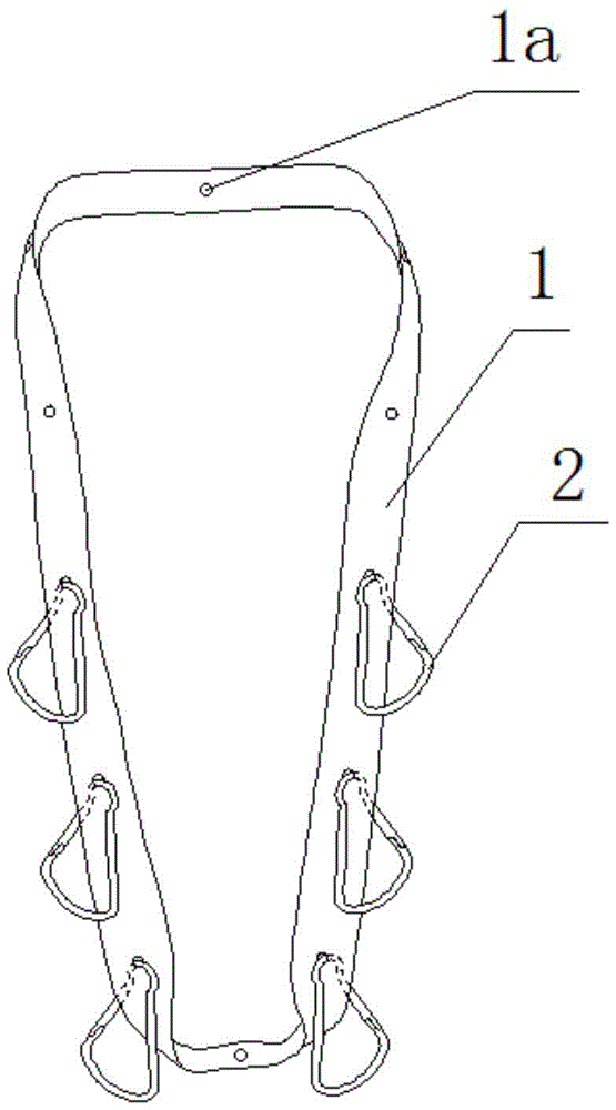
图1是本实用新型一个实施例的结构示意图;Fig. 1 is the structural representation of one embodiment of the present utility model;
图2是本实用新型一个实施例中固定装置本体的结构示意图;2 is a schematic structural diagram of a fixing device body in an embodiment of the present invention;
图3是本实用新型一个实施例中悬挂装置的结构示意图。FIG. 3 is a schematic structural diagram of a suspension device in an embodiment of the present invention.
附图标记说明Description of reference numerals
1 固定装置本体 1a 通孔1 Fixing device body 1a Through hole
2 悬挂装置 22 第二搭边2
21 第一搭边21 The first edge
具体实施方式Detailed ways
以下结合附图对本实用新型的具体实施方式进行详细说明。应当理解的是,此处所描述的具体实施方式仅用于说明和解释本实用新型,并不用于限制本实用新型。The specific embodiments of the present invention will be described in detail below with reference to the accompanying drawings. It should be understood that the specific embodiments described herein are only used to illustrate and explain the present invention, and are not used to limit the present invention.
需要说明的是,术语“第一”、“第二”仅用于描述的目的,而不能理解为指示或暗示相对重要性或隐含指明所指示的技术特征的数量,因此,限定有“第一”、“第二”的特征可以明示或隐含地包括一个或更多个所述特征。It should be noted that the terms "first" and "second" are only used for the purpose of description, and cannot be understood as indicating or implying relative importance or indicating the number of technical features indicated. A", "second" features may expressly or implicitly include one or more of the stated features.
在本实用新型的描述中,需要说明的是,除非另有明确的规定和限定,术语“安装”、“连接”应做广义理解,例如,可以是固定连接,也可以是可拆卸连接,或者是一体连接;可以是直接连接,也可以是通过中间媒介间接连接,可以是两个元件内部的连通或两个元件的相互作用关系。对于本领域的普通技术人员而言,可以根据具体情况理解上述术语在本实用新型中的具体含义。In the description of the present invention, it should be noted that, unless otherwise expressly specified and limited, the terms "installation" and "connection" should be understood in a broad sense, for example, it may be a fixed connection or a detachable connection, or It is an integral connection; it can be a direct connection or an indirect connection through an intermediate medium, and it can be the internal communication of two elements or the interaction relationship between the two elements. For those of ordinary skill in the art, the specific meanings of the above terms in the present invention can be understood according to specific situations.
如图1和2所示,本实用新型的一个实施例提供一种头部引流袋固定装置,包括固定装置本体1,所述固定装置本体1上沿着长度方向设有多个贯穿所述固定装置本体1的通孔1a,所述各个通孔1a的周缘设有防磨损结构。As shown in Figures 1 and 2, an embodiment of the present invention provides a head drainage bag fixing device, including a fixing device body 1, and the fixing device body 1 is provided with a plurality of through the fixing device along the length direction. The through holes 1a of the device body 1 are provided with anti-wear structures on the periphery of each through hole 1a.
如图1和3所示,在本实用新型的一个实施例中,还包括悬挂装置2,所述悬挂装置2的相对两侧为圆弧段,两条所述圆弧段之间位两条直线段,任一所述直线段上设有适于自动闭合的开口。As shown in FIGS. 1 and 3 , in an embodiment of the present invention, a
本实用新型一些实施例的使用过程为:取出固定装置本体1和悬挂装置2,固定装置本体1套在患者的脖子上,悬挂装置2可根据患者身上留置的头部引流袋的数量确定,通过设置在悬挂装置2上的开口将悬挂装置2悬挂在固定装置本体1上,头部引流袋也通过开口悬挂在悬挂装置2上,在悬挂头部引流袋时需要注意的是:第一,头部引流袋的数量建议不要超过六个,以免悬挂过多而对患者颈椎及表面软组织造成损伤;第二,头部引流袋悬挂时尽量对称分布,以免影响头部引流袋正常工作。The use process of some embodiments of the present invention is as follows: take out the fixing device body 1 and the
作为本实用新型的一种优选地结构形式,所述固定装置本体1为一体的环形结构,可方便患者直接将固定装置本体1悬挂在患者的脖子上,操作便捷。As a preferred structural form of the present invention, the fixing device body 1 is an integral annular structure, which can facilitate the patient to directly hang the fixing device body 1 on the patient's neck, and the operation is convenient.
作为本实用新型的另一种优选地结构形式,所述固定装置本体1为柔性织物成型。在现有多种柔性织物中,优选棉性织物和麻纱织物,棉性织物以棉花为原料,具有较好的吸湿性、保湿性、耐热性、耐碱性和卫生性的特点,能够很好的保护患者身体与所述固定装置本体1接触的部分的皮肤。As another preferred structural form of the present invention, the fixing device body 1 is formed of a flexible fabric. Among the various existing flexible fabrics, cotton fabrics and hemp yarn fabrics are preferred. Cotton fabrics are made of cotton and have the characteristics of good hygroscopicity, moisture retention, heat resistance, alkali resistance and hygiene. It is good to protect the skin of the part of the patient's body that is in contact with the fixture body 1 .
作为本实用新型的一种具体地结构形式,所述固定装置本体1宽度为5-8cm,过宽或过窄的固定装置本体1都会降低患者使用时的舒适度。As a specific structural form of the present invention, the width of the fixing device body 1 is 5-8 cm, and the fixing device body 1 that is too wide or too narrow will reduce the comfort of the patient during use.
作为本实用新型的另一种具体地结构形式,所述开口一侧为第一搭边21,另一侧为第二搭边22,所述第一搭边21和所述第二搭边22相互接触的面上设有磁性吸附装置。As another specific structural form of the present invention, one side of the opening is a
更具体地,所述悬挂装置2采用ABS工程塑料成型。More specifically, the
由以上描述可以看出,通过在固定装置本体1上沿着长度方向设有多个贯穿所述固定装置本体厚度的通孔1a,各通孔1a的周缘设有防磨损结构,同时还包括悬挂装置2,该悬挂装置2通过通孔1a与固定装置本体1连接。头部引流袋通过悬挂装置2与本实用新型的头部引流袋固定装置连接,本实用新型的头部引流袋固定装置可直接悬挂在患者的脖子上,使用方便,结构简单,且固定装置本体1经过消毒后可多次使用,避免资源浪费。It can be seen from the above description that the fixing device body 1 is provided with a plurality of through holes 1a penetrating the thickness of the fixing device body along the length direction, the periphery of each through hole 1a is provided with an anti-wear structure, and also includes
以上结合附图详细描述了本实用新型的优选实施方式,但是,本实用新型并不限于上述实施方式中的具体细节,在本实用新型的技术构思范围内,可以对本实用新型的技术方案进行多种简单变型,这些简单变型均属于本实用新型的保护范围。The preferred embodiments of the present invention have been described in detail above with reference to the accompanying drawings. However, the present invention is not limited to the specific details of the above-mentioned embodiments. Within the scope of the technical concept of the present invention, many technical solutions of the present invention can be carried out. These simple modifications all belong to the protection scope of the present invention.
另外需要说明的是,在上述具体实施方式中所描述的各个具体技术特征,在不矛盾的情况下,可以通过任何合适的方式进行组合,为了避免不必要的重复,本实用新型对各种可能的组合方式不再另行说明。In addition, it should be noted that the specific technical features described in the above-mentioned specific embodiments can be combined in any suitable manner unless they are inconsistent. The combination method is not specified otherwise.
此外,本实用新型的各种不同的实施方式之间也可以进行任意组合,只要其不违背本实用新型的思想,其同样应当视为本实用新型所公开的内容。In addition, the various embodiments of the present invention can also be arbitrarily combined, as long as they do not violate the idea of the present invention, they should also be regarded as the content disclosed by the present invention.
Claims (7)
Priority Applications (1)
| Application Number | Priority Date | Filing Date | Title |
|---|---|---|---|
| CN201920084678.0U CN210056899U (en) | 2019-01-17 | 2019-01-17 | Head drainage bag fixing device |
Applications Claiming Priority (1)
| Application Number | Priority Date | Filing Date | Title |
|---|---|---|---|
| CN201920084678.0U CN210056899U (en) | 2019-01-17 | 2019-01-17 | Head drainage bag fixing device |
Publications (1)
| Publication Number | Publication Date |
|---|---|
| CN210056899U true CN210056899U (en) | 2020-02-14 |
Family
ID=69424713
Family Applications (1)
| Application Number | Title | Priority Date | Filing Date |
|---|---|---|---|
| CN201920084678.0U Expired - Fee Related CN210056899U (en) | 2019-01-17 | 2019-01-17 | Head drainage bag fixing device |
Country Status (1)
| Country | Link |
|---|---|
| CN (1) | CN210056899U (en) |
-
2019
- 2019-01-17 CN CN201920084678.0U patent/CN210056899U/en not_active Expired - Fee Related
Similar Documents
| Publication | Publication Date | Title |
|---|---|---|
| CN204121092U (en) | An artificial chord device, threading element and kit | |
| CN209695910U (en) | A kind of fixed bracket of adjustable head portion drainage bag | |
| CN112426304B (en) | Adjustable head and neck position fixer | |
| CN209848108U (en) | Stomach tube fixing device | |
| CN210932390U (en) | Postoperative care head fixing device | |
| CN210872475U (en) | A kind of nasal mask for post-operative care of rhinology | |
| CN204158779U (en) | The fixture of Medical head operative drainage device | |
| CN110123526B (en) | Medical dressing | |
| CN207370922U (en) | Mammary gland patient's postoperative drainage fixing device | |
| WO2014169741A1 (en) | Catheter securing strap | |
| US2519712A (en) | Constrictor | |
| CN206080822U (en) | About band suitable for position safety in surgery surgery patient art | |
| CN217187181U (en) | Multifunctional drainage bag hanger | |
| CN202409731U (en) | Novel intravenous infusion fixing device | |
| CN217510980U (en) | Fixing device of postoperative drainage tube | |
| CN211835738U (en) | Surgical drainage tube fixing device | |
| CN221787809U (en) | Adjustable portable drainage fixing device | |
| CN211724180U (en) | Urine collecting bag | |
| CN217697425U (en) | A drainage tube protection device | |
| CN207341808U (en) | A kind of operation with diplopore cut open by | |
| CN217041043U (en) | Fixator for ventricular drainage tube | |
| CN216908777U (en) | A combined urine collection bag for medical care | |
| CN220530415U (en) | Negative pressure drainage fixing device | |
| CN221731173U (en) | A convenient fixed nursing pad | |
| CN208958244U (en) | A trauma hemostatic device for emergency department |
Legal Events
| Date | Code | Title | Description |
|---|---|---|---|
| GR01 | Patent grant | ||
| GR01 | Patent grant | ||
| CF01 | Termination of patent right due to non-payment of annual fee | ||
| CF01 | Termination of patent right due to non-payment of annual fee |
Granted publication date: 20200214 Termination date: 20220117 |