CN210048253U - A textile pay-off equipment - Google Patents
A textile pay-off equipment Download PDFInfo
- Publication number
- CN210048253U CN210048253U CN201920430492.6U CN201920430492U CN210048253U CN 210048253 U CN210048253 U CN 210048253U CN 201920430492 U CN201920430492 U CN 201920430492U CN 210048253 U CN210048253 U CN 210048253U
- Authority
- CN
- China
- Prior art keywords
- welded
- pay
- support column
- wall
- sleeve
- Prior art date
- Legal status (The legal status is an assumption and is not a legal conclusion. Google has not performed a legal analysis and makes no representation as to the accuracy of the status listed.)
- Expired - Fee Related
Links
Images




Landscapes
- Treatment Of Fiber Materials (AREA)
Abstract
本实用新型属于纺织设备领域,尤其涉及一种纺织放线设备,包括固定底座,固定底座的顶部焊接有支撑柱,支撑柱的外壁焊接有两个限位块,且支撑柱的外壁位于两个限位块之间套设有圆套。本实用新型中,可以用手握住均匀分布的多个圆杆,便可以将不同内径的放线筒套设在多个圆杆的外侧,松开手,在气囊的作用下,圆杆会进行复位,与放线筒内壁紧密贴合,实现对不同内径的放线筒,方便的进行安装或者拆卸,还可以将线穿过走线块内的线孔,在线发生晃动时,弹簧能够有效的进行防振固定,避免线发生大幅度的晃动和扯断,提升安全性,设置有可以滚动的滚球,能够减少摩擦,提升放线效率。

The utility model belongs to the field of textile equipment, in particular to a textile pay-off equipment, which comprises a fixed base, a support column is welded on the top of the fixed base, two limit blocks are welded on the outer wall of the support column, and the outer wall of the support column is located in two A round sleeve is sleeved between the limit blocks. In the utility model, the evenly distributed round rods can be held by hand, and the pay-off cylinders with different inner diameters can be sleeved on the outside of the plurality of round rods, and the hand can be released. It is reset and closely fitted with the inner wall of the spool, so that the spools with different inner diameters can be easily installed or disassembled, and the wire can also be passed through the wire hole in the wiring block. When the wire shakes, the spring can effectively Anti-vibration fixation can be carried out to avoid large-scale shaking and breaking of the line, and improve safety. It is equipped with a rolling ball that can reduce friction and improve the efficiency of pay-off.
Description
技术领域technical field
本实用新型属于纺织设备技术领域,尤其涉及一种纺织放线设备。The utility model belongs to the technical field of textile equipment, in particular to a textile pay-off equipment.
背景技术Background technique
纺织机,又叫纺机、织机、棉纺机等,就是把线、丝、麻等原材料加工成丝线后织成布料的工具全称,随着人们生活水平的提高和纺织领域的不断发展,纺织设备以及技术的水平也在断发展,其中,放线装置是纺织设备中不可或缺的部分之一。Textile machine, also known as spinning machine, loom, cotton spinning machine, etc., is the full name of the tool for processing thread, silk, hemp and other raw materials into silk thread and then weaving it into fabric. With the improvement of people's living standards and the continuous development of the textile field, textile The level of equipment and technology is also constantly developing, among which, the pay-off device is one of the indispensable parts of textile equipment.
但是,现有技术中的纺织放线设备,一般是将放线筒直接套在固定柱上,随着放线的进行,放线筒会在固定柱上转动,放线筒和固定柱之间会有摩擦,影响放线效率,对于不同内径的放线筒,需要特定的固定柱,通用性不佳,放线筒也易倾倒,同时,放线过程中,线容易发生大幅度的晃动,会折断,缺少一定的走线控制组件,无法满足使用者对于纺织放线设备的需求。However, in the textile pay-off equipment in the prior art, the pay-off barrel is generally directly sleeved on the fixed column, and as the pay-off proceeds, the pay-off barrel will rotate on the fixed column, and between the pay-off barrel and the fixed column There will be friction, which will affect the pay-off efficiency. For pay-off spools with different inner diameters, a specific fixing column is required, which is not universal, and the pay-off spool is easy to fall. It will be broken, lack of certain wiring control components, and cannot meet the needs of users for textile pay-off equipment.
实用新型内容Utility model content
本实用新型针对上述的问题,提供了一种纺织放线设备。Aiming at the above problems, the utility model provides a textile pay-off device.
为了达到上述目的,本实用新型采用的技术方案为,本实用新型提供一种纺织放线设备,包括固定底座,所述固定底座的顶部焊接有支撑柱,所述支撑柱的外壁焊接有两个限位块,且支撑柱的外壁位于两个限位块之间套设有圆套,所述支撑柱的外壁位于两个限位块的上方焊接有第一圆盘,且支撑柱的外壁位于第一圆盘的顶部转动套设有第二圆盘,并且支撑柱的顶部焊接有定位块,所述第二圆盘的顶部中心处焊接有套筒。In order to achieve the above purpose, the technical solution adopted by the present invention is that the present invention provides a textile pay-off device, comprising a fixed base, the top of the fixed base is welded with a support column, and the outer wall of the support column is welded with two The limit block, and the outer wall of the support column is located between the two limit blocks with a circular sleeve, the outer wall of the support column is located above the two limit blocks and welded with a first disc, and the outer wall of the support column is located at the top of the two limit blocks. The top of the first disk is rotatably provided with a second disk, the top of the support column is welded with a positioning block, and the center of the top of the second disk is welded with a sleeve.
作为优选,所述套筒的外壁上均匀焊接有伸缩组件,且伸缩组件的另一端焊接有圆杆。Preferably, the outer wall of the sleeve is uniformly welded with telescopic components, and the other end of the telescopic components is welded with a round rod.
作为优选,所述伸缩组件包含粗管,所述粗管的一端与套筒焊接,另一端中心处滑动嵌设有细杆,所述细杆的一端与圆杆焊接,另一端焊接有压块,且压块的另一侧粘合有气囊,并且气囊的另一侧与套筒连接。Preferably, the telescopic assembly includes a thick pipe, one end of the thick pipe is welded with the sleeve, and a thin rod is slidably embedded in the center of the other end, one end of the thin rod is welded with the round rod, and the other end is welded with a pressure block , and the other side of the pressing block is bonded with an air bag, and the other side of the air bag is connected with the sleeve.
作为优选,所述圆套的一侧焊接有连接杆,所述连接杆的顶部焊接有框体,所述圆套内嵌设有螺纹杆。Preferably, a connecting rod is welded on one side of the circular sleeve, a frame body is welded on the top of the connecting rod, and a threaded rod is embedded in the circular sleeve.
作为优选,所述框体内沿竖直方向焊接有两个滑杆,且两个滑杆的外壁套设有两个滑块,并且两个滑块的对应端焊接有走线块,两个所述滑杆的外壁位于两个滑块的底部套设有两个弹簧,且两个弹簧的两端分别与两个滑块和框体内壁焊接。Preferably, two sliding rods are welded in the vertical direction in the frame, and two sliding blocks are sleeved on the outer walls of the two sliding rods, and the corresponding ends of the two sliding blocks are welded with wiring blocks. The outer wall of the sliding rod is located at the bottom of the two sliding blocks and is sleeved with two springs, and both ends of the two springs are respectively welded with the two sliding blocks and the inner wall of the frame.
作为优选,所述第一圆盘的顶部嵌设有多个滚球,所述第二圆盘的底部开设有与多个滚球相对应的环槽。Preferably, a plurality of rolling balls are embedded at the top of the first disc, and annular grooves corresponding to the plurality of rolling balls are formed at the bottom of the second disc.
与现有技术相比,本实用新型的优点和积极效果在于,Compared with the prior art, the advantages and positive effects of the present invention are:
1、本实用新型中:可以用手握住均匀分布的多个圆杆,圆杆受到手掌的握力,会带动细杆在粗管内滑动,压块会对气囊进行挤压,此时,便可以将不同内径的放线筒套设在多个圆杆的外侧,松开手,在气囊的作用下,圆杆会进行复位,与放线筒内壁紧密贴合,实现多不同内径的放线筒进可以方便的进行安装或者拆卸。1. In the present utility model: a plurality of circular rods evenly distributed can be held by hand, and the circular rods are subjected to the grip force of the palm, which will drive the thin rods to slide in the thick tube, and the pressure block will squeeze the airbag. Set the pay-off reels with different inner diameters on the outside of multiple round rods, release your hand, and under the action of the air bag, the round rods will reset and fit closely with the inner wall of the pay-off reels to realize multiple pay-off reels with different internal diameters. It can be easily installed or disassembled.
2、本实用新型中:还可以将线穿过走线块内的线孔,在线发生晃动时,滑块会在滑杆上滑动,对弹簧进行挤压或者拉伸,弹簧能够有效的进行防振固定,避免线发生大幅度的晃动和扯断,提升安全性。2. In the present utility model: the wire can also be passed through the wire hole in the wire routing block. When the wire shakes, the slider will slide on the sliding rod, and the spring will be squeezed or stretched, and the spring can effectively prevent Vibration fixed to avoid large shaking and tearing of the wire, and improve safety.
3、本实用新型中:在第二圆盘的顶部嵌设有可以滚动的滚球,在第一圆盘转动时,滚球会随着发生滚动,能够减少摩擦,提升放线效率。3. In the present utility model, a rolling ball is embedded on the top of the second disc. When the first disc rotates, the rolling ball will roll along with it, which can reduce friction and improve the pay-off efficiency.
附图说明Description of drawings
为了更清楚地说明本实用新型实施例的技术方案,下面将对实施例描述中所需要使用的附图作一简单地介绍,显而易见地,下面描述中的附图是本实用新型的一些实施例,对于本领域普通技术人员来讲,在不付出创造性劳动性的前提下,还可以根据这些附图获得其他的附图。In order to illustrate the technical solutions of the embodiments of the present invention more clearly, the following briefly introduces the accompanying drawings used in the description of the embodiments. Obviously, the drawings in the following description are some embodiments of the present invention. , for those of ordinary skill in the art, other drawings can also be obtained from these drawings without creative labor.
图1为本实用新型提供的一种纺织放线设备的示意图;Fig. 1 is the schematic diagram of a kind of textile pay-off equipment provided by the utility model;
图2为本实用新型提供的一种纺织放线设备的A处放大的结构示意图;Fig. 2 is the enlarged structural representation of the A place of a kind of textile pay-off equipment provided by the utility model;
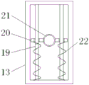
图3为本实用新型提供的一种纺织放线设备的框体内部连接的示意图;3 is a schematic diagram of the internal connection of the frame body of a textile pay-off device provided by the utility model;
图4为本实用新型提供的一种纺织放线设备的套筒连接的示意图;Fig. 4 is the schematic diagram of the sleeve connection of a kind of textile pay-off equipment provided by the utility model;
图5为本实用新型提供的一种纺织放线设备的第二圆盘的示意图。Fig. 5 is a schematic diagram of a second disc of a textile pay-off device provided by the utility model.
以上各图中,1、固定底座;2、支撑柱;3、限位块;4、圆套;5、螺纹杆; 6、第一圆盘;7、滚球;8、第二圆盘;81、环槽;9、定位块;10、套筒;11、圆杆;12、伸缩组件;13、框体;14、连接杆;15、粗管;16、细杆;17、压块;18、气囊;19、滑杆;20、滑块;21、走线块;22、弹簧。In the above figures, 1. Fixed base; 2. Support column; 3. Limit block; 4. Round sleeve; 5. Threaded rod; 6. First disc; 7. Rolling ball; 8. Second disc; 81, ring groove; 9, positioning block; 10, sleeve; 11, round rod; 12, telescopic assembly; 13, frame body; 14, connecting rod; 15, thick pipe; 16, thin rod; 17, pressing block; 18. Airbag; 19. Slider; 20. Slider; 21. Cable block; 22. Spring.
具体实施方式Detailed ways
为了能够更清楚地理解本实用新型的上述目的、特征和优点,下面结合附图和实施例对本实用新型做进一步说明。需要说明的是,在不冲突的情况下,本申请的实施例及实施例中的特征可以相互组合。In order to be able to understand the above-mentioned objects, features and advantages of the present invention more clearly, the present invention will be further described below with reference to the accompanying drawings and embodiments. It should be noted that the embodiments of the present application and the features in the embodiments may be combined with each other in the case of no conflict.
在下面的描述中阐述了很多具体细节以便于充分理解本实用新型,但是,本实用新型还可以采用不同于在此描述的其他方式来实施,因此,本实用新型并不限于下面公开说明书的具体实施例的限制。In the following description, many specific details are set forth in order to fully understand the present invention. However, the present invention can also be implemented in other ways different from those described herein. Therefore, the present invention is not limited to the specific details of the following disclosure. Example limitations.
实施例1,如图1所示,本实用新型提供了一种纺织放线设备,包括固定底座1,固定底座1可以与其他外界物体连接,对整个装置起到支撑作用,固定底座1的顶部焊接有支撑柱2,支撑柱2的外壁焊接有两个限位块3,且支撑柱2的外壁位于两个限位块3之间套设有圆套4,两个限位块3起到对圆套4 的限位作用,圆套4可以在支撑柱2上转动,调整连接杆14的朝向,支撑柱2 的外壁位于两个限位块3的上方焊接有第一圆盘6,且支撑柱2的外壁位于第一圆盘6的顶部转动套设有第二圆盘8,第一圆盘6与支撑柱2固定焊接,第二圆盘8可以在支撑柱2上转动,并且支撑柱2的顶部焊接有定位块9,定位块9起到对第二圆盘8的限位作用,防止第二圆盘8脱离支撑柱2,第二圆盘8 的顶部中心处焊接有套筒10。
如图1、图2和图4所示,在使用时,为了能够对不同大小内径的放线筒进行安装,设计人员在套筒10的外壁上均匀焊接有伸缩组件12,伸缩组件12 包含粗管15,粗管15的一端与套筒10焊接,另一端中心处滑动嵌设有细杆16,细杆16的一端与圆杆11焊接,另一端焊接有压块17,且压块17的另一侧粘合有气囊18,气囊18由橡胶材料构成,内部形成内腔,并且气囊18的另一侧与套筒10连接,另外在伸缩组件12的另一端焊接有圆杆11,使得使用者,可以在安装放线筒时,用手握住外侧多个圆杆11,圆杆11会带动细杆16在粗管 15内滑动,带动压块17对气囊18进行挤压,便实现了多个圆杆11的靠近,实现了对于不同内径的放线筒均可以使用的目的,能够便于使用者安装和取下放线筒。As shown in Fig. 1, Fig. 2 and Fig. 4, in use, in order to be able to install spools with different sizes of inner diameters, the designer uniformly welds
实施例2,如图1、图3和图5所示,为了解决在放线过程中,线容易发生晃动的问题,设计人员在圆套4的一侧焊接有连接杆14,连接杆14的顶部焊接有框体13,框体13内沿竖直方向焊接有两个滑杆19,且两个滑杆19的外壁套设有两个滑块20,并且两个滑块20的对应端焊接有走线块21,两个滑杆19 的外壁位于两个滑块20的底部套设有两个弹簧22,且两个弹簧22的两端分别与两个滑块20和框体13内壁焊接,走线块21中心处开设有线孔,可以将线贯穿线孔,在线发生晃动时,会带动两个滑块20在滑杆19上滑动,由于在滑杆 19上设置有弹簧22,可以使得弹簧22起到有效的对滑块20进行防振固定的效果,能够有效的避免,放线过程中线发生晃动,提升放线的稳定性,该装置还在圆套4内嵌设有螺纹杆5,可以通过拧动螺纹杆5,实现螺纹杆5与支撑柱2 的挤压,即实现对圆套4的固定,从而改变框体13所处的位置,满足不同方向的放线要求,在第一圆盘6的顶部嵌设有多个滚球7,第二圆盘8的底部开设有与多个滚球7相对应的环槽81,可以在放线过程中,使得放线筒随第二圆盘 8在第一圆盘6上转动,滚球7起到减少摩擦的作用。
工作原理:使用时,可以用手握住多个圆杆11,圆杆11带动细杆16在粗管15内滑动,使得压块17对气囊18进行挤压,便可以对不同内径的放线筒进行安装,将放线筒套设在多个圆杆11上,松开手,便实现了对不同内径的放线筒的固定,将引线穿过走线块21开设的线孔,连接到其他设备上,当进行放线时,放线筒会发生转动,通过套筒10带动第二圆盘8在支撑柱2上转动,在第一圆盘6上设置有滚球7,可以减少摩擦,便于进行放线,在放线的过程中,线会发生晃动,带动走线块21晃动,使得两个滑块20在滑杆19对弹簧22进行压缩或者拉伸,弹簧22可以有效的起到防振固定作用,能够避免线发生大幅度的晃动,提升走线的稳定性,避免线折断,在圆套4内螺纹连接有螺纹杆5,可以转动圆套4,改变框体13的位置,再拧紧螺纹杆5,随着螺纹杆5的拧动,会与支撑柱2接触挤压,实现对圆套4的固定,即可以实现对不同方向进行放线。Working principle: When using, you can hold a plurality of
以上所述,仅是本实用新型的较佳实施例而已,并非是对本实用新型作其它形式的限制,任何熟悉本专业的技术人员可能利用上述揭示的技术内容加以变更或改型为等同变化的等效实施例应用于其它领域,但是凡是未脱离本实用新型技术方案内容,依据本实用新型的技术实质对以上实施例所作的任何简单修改、等同变化与改型,仍属于本实用新型技术方案的保护范围。The above is only a preferred embodiment of the present invention, and is not intended to limit the present invention in other forms. Any person skilled in the art may use the technical content disclosed above to change or remodel to equivalent changes. The equivalent embodiments are applied in other fields, but any simple modifications, equivalent changes and modifications made to the above embodiments according to the technical essence of the present utility model still belong to the technical solutions of the present utility model without departing from the technical solution content of the present utility model. scope of protection.
Claims (6)
Priority Applications (1)
| Application Number | Priority Date | Filing Date | Title |
|---|---|---|---|
| CN201920430492.6U CN210048253U (en) | 2019-04-01 | 2019-04-01 | A textile pay-off equipment |
Applications Claiming Priority (1)
| Application Number | Priority Date | Filing Date | Title |
|---|---|---|---|
| CN201920430492.6U CN210048253U (en) | 2019-04-01 | 2019-04-01 | A textile pay-off equipment |
Publications (1)
| Publication Number | Publication Date |
|---|---|
| CN210048253U true CN210048253U (en) | 2020-02-11 |
Family
ID=69379981
Family Applications (1)
| Application Number | Title | Priority Date | Filing Date |
|---|---|---|---|
| CN201920430492.6U Expired - Fee Related CN210048253U (en) | 2019-04-01 | 2019-04-01 | A textile pay-off equipment |
Country Status (1)
| Country | Link |
|---|---|
| CN (1) | CN210048253U (en) |
Cited By (2)
| Publication number | Priority date | Publication date | Assignee | Title |
|---|---|---|---|---|
| CN112794163A (en) * | 2021-02-05 | 2021-05-14 | 陈健 | Spinning bobbin |
| CN113044654A (en) * | 2021-02-02 | 2021-06-29 | 方晓菡 | Winder for loom with conveniently replaced winding part |
-
2019
- 2019-04-01 CN CN201920430492.6U patent/CN210048253U/en not_active Expired - Fee Related
Cited By (3)
| Publication number | Priority date | Publication date | Assignee | Title |
|---|---|---|---|---|
| CN113044654A (en) * | 2021-02-02 | 2021-06-29 | 方晓菡 | Winder for loom with conveniently replaced winding part |
| CN112794163A (en) * | 2021-02-05 | 2021-05-14 | 陈健 | Spinning bobbin |
| CN112794163B (en) * | 2021-02-05 | 2023-09-19 | 陕西银华纺织有限责任公司 | Textile bobbin |
Similar Documents
| Publication | Publication Date | Title |
|---|---|---|
| CN206060147U (en) | The simple pay off rack of low pressure | |
| CN108423483A (en) | A kind of bobbin winder device of multiply metal wire | |
| CN211712271U (en) | Weaving bobbin positioner for weaving machine | |
| CN207551561U (en) | A kind of wire-rewinding structure for cable production line | |
| CN216072483U (en) | Portable multifunctional winding reel for textile industry | |
| CN217808032U (en) | A kind of textile thread bobbin for weaving | |
| CN108563345A (en) | A kind of mouse of the collapsible mouse lines of computer | |
| CN204576386U (en) | Computer cables fixes draw off gear automatically | |
| CN209427848U (en) | A kind of spool apparatus for placing of Garment hanging beads production line | |
| CN104973459A (en) | Textile machine yarn bobbin facilitating guiding of yarn | |
| CN210104150U (en) | A texturing machine original wire rack with continuous wire feeding function | |
| CN203392618U (en) | Manual pay-off rack | |
| CN213835826U (en) | A sewing machine thread clamping device | |
| CN209668528U (en) | A kind of Textile machine bobbin | |
| CN208594363U (en) | A kind of weaving weft yarn rack | |
| CN105905669A (en) | A spinning device for textile | |
| CN207293816U (en) | A kind of colour-spun yarns reel | |
| CN106212402A (en) | A kind of fishbook tying device and operational approach | |
| CN107854074A (en) | A kind of telescopic novel mop of holding rod | |
| CN207293772U (en) | A kind of photoelectricity accessory bobbin winoler easy to coiling | |
| JP2014139096A5 (en) | ||
| CN210655598U (en) | Add former guide frame of bullet machine with anti-drop function | |
| CN104418182A (en) | Spinning bobbin | |
| CN205257676U (en) | Threading net holding frame | |
| CN104609258B (en) | Tension pay-off creel |
Legal Events
| Date | Code | Title | Description |
|---|---|---|---|
| GR01 | Patent grant | ||
| GR01 | Patent grant | ||
| CF01 | Termination of patent right due to non-payment of annual fee | ||
| CF01 | Termination of patent right due to non-payment of annual fee |
Granted publication date: 20200211 |