CN210029950U - A convenient lift - Google Patents
A convenient lift Download PDFInfo
- Publication number
- CN210029950U CN210029950U CN201920681694.8U CN201920681694U CN210029950U CN 210029950 U CN210029950 U CN 210029950U CN 201920681694 U CN201920681694 U CN 201920681694U CN 210029950 U CN210029950 U CN 210029950U
- Authority
- CN
- China
- Prior art keywords
- guardrail
- rod
- convenient
- platform
- grid
- Prior art date
- Legal status (The legal status is an assumption and is not a legal conclusion. Google has not performed a legal analysis and makes no representation as to the accuracy of the status listed.)
- Active
Links
Images


Landscapes
- Handcart (AREA)
Abstract
一种便捷升降机,属于工程机械技术领域,结构上包括升降机主体,通过在护栏上安装工具放置箱,通过磁铁和挂钩固定与护栏的连接,同时磁铁能够吸附金属类的工具避免掉落,而在护栏底端设置弹簧杆与其连接,使弹簧的弹力能够增加承重的同时,加强顶端平台的稳定性,减少平台升高后左右摇晃引起的上下晃动,其结构新颖,使用便捷,由于工具放置箱的设置,杜绝了传统升降机操作工具与货物产生剐蹭掉落的危险,节省了平台使用空间,提高了承载安全性能。
A convenient lifting platform, belonging to the field of engineering machinery technology, includes a lifting platform body. A tool storage box is installed on the guardrail and fixed to the guardrail by magnets and hooks. The magnets attract metal tools to prevent them from falling. A spring rod is installed at the bottom of the guardrail and connected to it. The spring force increases the load-bearing capacity and enhances the stability of the top platform, reducing vertical swaying caused by lateral movement after the platform is raised. Its novel structure and convenient use, combined with the tool storage box, eliminate the danger of tools and goods scraping and falling, saving platform space and improving load-bearing safety performance.
Description
技术领域technical field
本实用新型属于工程机械技术领域,涉及一种升降机,特别涉及一种便捷升降机。The utility model belongs to the technical field of construction machinery, and relates to a lift, in particular to a convenient lift.
背景技术Background technique
剪叉式升降机是用途广泛的高空作业专用设备,剪叉式机械结构,使升降台起升后有较高的稳定性,宽大的作业平台和较高的承载能力,使高空作业范围更大,高空作业效率更高,安全性能高,是用途广泛的高空作业升降设备。Scissor lift is a wide range of special equipment for high-altitude work. The scissor-type mechanical structure enables the lifting platform to have high stability after lifting. The wide working platform and high bearing capacity make the high-altitude work range larger. The aerial work has higher efficiency and high safety performance, and is a widely used aerial work lifting equipment.
但是,目前的剪叉式升降机无法承载较重的货物,使垂直运输需要人力的辅助,同时在运输货物的同时,由于作业平台上需要站人,使得工具只能够挂载在身上,当与货物产生剐蹭时,工具会从高处掉落引起危险,因此实用性不强。However, the current scissor lift cannot carry heavier goods, so that the vertical transportation needs the assistance of manpower. At the same time, when the goods are transported, because people need to stand on the working platform, the tools can only be mounted on the body, and when the goods are transported, the tools can only be mounted on the body. When a scratch occurs, the tool will fall from a height and cause danger, so it is not practical.
实用新型内容Utility model content
本实用新型的目的是针对目前剪叉式升降机无法承载较重的货物,垂直运输需要人力的辅助,操作工具与货物产生剐蹭时,从高处掉落引起危险,安全性能较差,实用性不强等缺陷,提出一种便捷升降机,利用升降机护栏进行结构改进,结构紧凑合理,可节省平台使用空间,提高其承载安全性能。The purpose of the utility model is to solve the problem that the current scissor lift cannot carry heavier goods, and the vertical transportation requires the assistance of manpower. Due to the defects such as strength, a convenient elevator is proposed, which uses the elevator guardrail to improve the structure. The structure is compact and reasonable, which can save the use space of the platform and improve its carrying safety performance.
本实用新型的技术方案是:一种便捷升降机,包括由底座、剪叉杆、顶平台和护栏构成的升降机主体;其特征在于:所述底座的一端安装有配电箱,所述剪叉杆的内侧安装有电液压杆,所述顶平台的顶端安装有弹簧杆,所述弹簧杆的上方设有六角螺钉,所述六角螺钉与弹簧杆之间设有卡板,所述护栏设置在所述弹簧杆的顶端,所述护栏的顶部一侧设有工具放置箱,所述工具放置箱由紧箍圈、网格、底盘和挂钩组成,所述紧箍圈设置在工具放置箱的顶端,所述紧箍圈的一侧设有两个挂钩,所述挂钩的底端一侧设有磁铁层,所述网格设置在所述紧箍圈的底端,所述底盘设置在所述网格的底端。The technical scheme of the utility model is: a convenient elevator, comprising a main body of the elevator consisting of a base, a scissor bar, a top platform and a guardrail; it is characterized in that a power distribution box is installed at one end of the base, and the scissor bar is An electro-hydraulic rod is installed on the inner side, a spring rod is installed on the top of the top platform, a hexagonal screw is arranged above the spring rod, a clamping plate is arranged between the hexagonal screw and the spring rod, and the guardrail is arranged at the The top of the spring rod, the top side of the guardrail is provided with a tool placement box, the tool placement box is composed of a tight hoop, a grid, a chassis and a hook, and the tight hoop is arranged on the top of the tool placement box, One side of the hoop is provided with two hooks, the bottom side of the hook is provided with a magnet layer, the grid is provided at the bottom end of the hoop, and the chassis is provided on the net. bottom of the grid.
所述底座的底端安装有万向轮,万向轮的个数为四个,万向轮呈中心对称安装。A universal wheel is installed at the bottom end of the base, the number of the universal wheel is four, and the universal wheel is installed symmetrically in the center.
所述电液压杆分别与剪叉杆和底座铰链连接,电液压杆和配电箱电性连接,剪叉杆分别与顶平台和底座铰链连接。The electro-hydraulic rod is hingedly connected with the scissor rod and the base, the electro-hydraulic rod is electrically connected with the distribution box, and the scissor rod is hingedly connected with the top platform and the base, respectively.
所述顶平台和弹簧杆固定连接,弹簧杆和护栏通过六角螺钉固定连接,卡板中部设置有六角孔洞,且六角孔洞与六角螺钉的螺帽大小相同。The top platform and the spring rod are fixedly connected, the spring rod and the guardrail are fixedly connected by hexagonal screws, and the middle of the card plate is provided with a hexagonal hole, and the hexagonal hole is the same size as the nut of the hexagonal screw.
所述挂钩分别与磁铁层和紧箍圈固定连接,磁铁层分别与紧箍圈和底盘固定连接,底盘和网格为包覆连接安装。The hooks are respectively fixedly connected with the magnet layer and the tightening hoop, the magnet layer is respectively fixedly connected with the tightening hoop and the chassis, and the chassis and the grid are installed by covering and connecting.
所述卡板的顶端表面设置有橡胶层,护栏由铁金属构成。The top surface of the card board is provided with a rubber layer, and the guardrail is made of iron metal.
本实用新型的有益效果为:本实用新型提供的一种便捷升降机,结构上包括升降机主体,通过在护栏上安装工具放置箱,通过磁铁和挂钩固定与护栏的连接,同时磁铁能够吸附金属类的工具避免掉落,而在护栏底端设置弹簧杆与其连接,使弹簧的弹力能够增加承重的同时,加强顶端平台的稳定性,减少平台升高后左右摇晃引起的上下晃动,其结构新颖,使用便捷,由于工具放置箱的设置,杜绝了传统升降机操作工具与货物产生剐蹭掉落的危险,节省了平台使用空间,提高了承载安全性能。The beneficial effects of the utility model are as follows: the utility model provides a convenient elevator, which includes a main body of the elevator in structure, and a tool placement box is installed on the guardrail, and the connection with the guardrail is fixed by magnets and hooks, and the magnet can absorb metal objects. The tool avoids falling, and a spring rod is set at the bottom of the guardrail to connect with it, so that the elastic force of the spring can increase the load bearing, and at the same time strengthen the stability of the top platform, and reduce the up and down shaking caused by the left and right shaking after the platform is raised. Convenient, due to the setting of the tool storage box, the danger of the traditional elevator operating tools and the goods being scraped and dropped is eliminated, the platform space is saved, and the carrying safety performance is improved.
附图说明Description of drawings
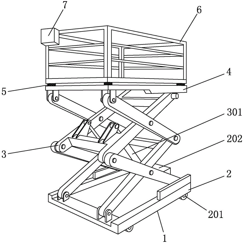
图1 是本实用新型的整体结构示意图。Figure 1 is a schematic diagram of the overall structure of the present invention.
图2 是本实用新型的弹簧杆结构示意图。FIG. 2 is a schematic diagram of the structure of the spring rod of the present invention.
图3 是本实用新型的卡板结构示意图。FIG. 3 is a schematic diagram of the structure of the card board of the present invention.
图4 是本实用新型的工具放置箱结构示意图。FIG. 4 is a schematic structural diagram of the tool placement box of the present invention.
图中:升降机主体1、底座2、万向轮201、配电箱202、剪叉杆3、电液压杆301、顶平台4、弹簧杆5、六角螺钉501、卡板502、护栏6、工具放置箱7、紧箍圈701、挂钩702、磁铁层703、网格704、底盘705。In the figure: elevator
具体实施方式Detailed ways
下面结合附图对本实用新型作进一步说明:Below in conjunction with accompanying drawing, the utility model is further described:
如图1-4所示,一种便捷升降机,包括由底座2、剪叉杆3、顶平台4和护栏6构成的升降机主体1,底座2的一端安装有配电箱202,剪叉杆3的内侧安装有电液压杆301,顶平台4的顶端安装有弹簧杆5,弹簧杆5的上方设有六角螺钉501,六角螺钉501与弹簧杆5之间设有卡板502,护栏6设置在弹簧杆(5)的顶端,护栏6的顶部一侧设有工具放置箱7,工具放置箱7由紧箍圈701、网格704、底盘705和挂钩702组成,紧箍圈701设置在工具放置箱7的顶端,紧箍圈701的一侧设有两个挂钩702,挂钩702的底端一侧设有磁铁层703,网格704设置在紧箍圈701的底端,底盘75设置在网格704的底端。As shown in Figures 1-4, a convenient lift includes a lift
如图1-4所示,一种便捷升降机,底座2的底端安装有万向轮201,万向轮201的个数为四个,万向轮201呈中心对称安装;电液压杆301分别与剪叉杆3和底座2铰链连接,电液压杆301和配电箱202电性连接,剪叉杆3分别与顶平台4和底座2铰链连接;顶平台4和弹簧杆5固定连接,弹簧杆5和护栏6通过六角螺钉501固定连接,卡板502中部设置有六角孔洞,且六角孔洞与六角螺钉501的螺帽大小相同;挂钩702分别与磁铁层703和紧箍圈701固定连接,磁铁层703分别与紧箍圈701和底盘705固定连接,底盘705和网格704为包覆连接安装;卡板502的顶端表面设置有橡胶层,护栏6由铁金属构成。As shown in Figures 1-4, a convenient lift, the bottom end of the
如图1-4所示,一种便捷升降机,电液压杆301分别与剪叉杆3和底座2铰链连接,电液压杆301和配电箱202电性连接,剪叉杆3分别与顶平台4和底座2铰链连接,使配电箱202通电后控制电液压杆301伸长,使得剪叉杆3随电液压杆301的伸长支撑一定高度。顶平台4和弹簧杆5固定连接,弹簧杆5和护栏6通过六角螺钉501固定连接,卡板502中部设置有六角孔洞,且六角孔洞与六角螺钉501的螺帽大小相同,使六角螺钉501可拧入卡板502内,从而保护六角螺钉501的完整性,同时护栏6底端的工作平台和弹簧杆5的连接,使其增加了稳定性,同时少量增加了可承重重量。挂钩702分别与磁铁层703和紧箍圈701固定连接,磁铁层703分别与紧箍圈701和底盘705固定连接,底盘705和网格704为包覆连接安装,使得磁铁层703受到紧箍圈701、底盘705和网格704的保护,磁铁层703将辅助挂钩702与护栏6产生吸附。剪叉杆3为高锰钢金属材料制作而成,使剪叉杆3更具有耐用性,增加了升降机主体1的使用寿命。卡板502的顶端表面设置有橡胶层,护栏6由铁金属构成,使得卡板502顶端受力后产生弹性受压,增加卡板502的使用寿命,而铁金属与磁铁具有较强的吸附能力,使磁铁层703可辅助固定工具放置箱7的位置。As shown in Figures 1-4, a convenient lift, the electro-
如图1-4所示,一种便捷升降机使用原理如下:升降机主体1的底座2经万向轮201卡死后,经配电箱202向电液压杆301通电,使电液压杆301撑起剪叉杆3,而剪叉杆3与顶平台4和底做2为铰链连接,顶平台4将撑起一定高度,同时在顶平台4顶端的弹簧杆5可减少护栏6的底端晃动,且弹簧杆5经卡板502和六角螺钉501与护栏6连接,使得护栏6底端的工作平台在固定连接的同时,可受到弹簧杆5所撑起的力从而增加少量承重,在护栏6的顶端一侧所设置的工具放置箱7则能够放置所需要使用的工具,且不影响工作平台的空间,而工具放置箱7上的挂钩702与护栏6连接,同时在挂钩702底端一侧的磁铁层703可辅助工具放置箱7的吸附,而在网格704内侧的金属工具可受到磁铁层703的吸附固定。As shown in Figure 1-4, a convenient elevator uses the following principles: after the
Claims (6)
Priority Applications (1)
| Application Number | Priority Date | Filing Date | Title |
|---|---|---|---|
| CN201920681694.8U CN210029950U (en) | 2019-05-13 | 2019-05-13 | A convenient lift |
Applications Claiming Priority (1)
| Application Number | Priority Date | Filing Date | Title |
|---|---|---|---|
| CN201920681694.8U CN210029950U (en) | 2019-05-13 | 2019-05-13 | A convenient lift |
Publications (1)
| Publication Number | Publication Date |
|---|---|
| CN210029950U true CN210029950U (en) | 2020-02-07 |
Family
ID=69365120
Family Applications (1)
| Application Number | Title | Priority Date | Filing Date |
|---|---|---|---|
| CN201920681694.8U Active CN210029950U (en) | 2019-05-13 | 2019-05-13 | A convenient lift |
Country Status (1)
| Country | Link |
|---|---|
| CN (1) | CN210029950U (en) |
-
2019
- 2019-05-13 CN CN201920681694.8U patent/CN210029950U/en active Active
Similar Documents
| Publication | Publication Date | Title |
|---|---|---|
| CN202717550U (en) | Electric lifting platform | |
| CN206375165U (en) | A kind of shock-absorbing type electromechanical equipment transports bearing | |
| CN205066897U (en) | Walking beam buffering coil of strip balance | |
| CN210944509U (en) | Plate hoisting clamping part for building construction | |
| CN204400421U (en) | A kind of gallows frame adopting electromagnet | |
| CN206172874U (en) | Loading and unloading goods is with fixed jack -up lifting device | |
| CN204689351U (en) | A kind of H profile steel structural elements suspender | |
| CN208516764U (en) | A protective hanging basket for distribution and hoisting of photovoltaic modules | |
| CN202296851U (en) | Concrete pole assembling and disassembling rack | |
| CN206806788U (en) | A kind of lifting base for box-type substation | |
| CN214590057U (en) | Power distribution cabinet convenient to mount and hoist | |
| CN103213899A (en) | Auxiliary grinding wheel hoisting device | |
| CN111908336B (en) | Four-corner guiding device for hoisting transformer hanging cover | |
| CN211034879U (en) | Lifting chain with high wear resistance | |
| CN205222562U (en) | Crane quick travel installation device with lift platform | |
| CN202508813U (en) | Detachable field distribution transformer transporting vehicle | |
| CN203715156U (en) | Convenient crane | |
| CN201801344U (en) | Jack provided with lever | |
| CN206126676U (en) | Dust free chamber rest hoist and mount A frame | |
| CN206425419U (en) | Workbench and its support component | |
| CN219364350U (en) | A bridge deck crane and its rear anchor mechanism | |
| CN221070092U (en) | Automatic stacking device for acrylic | |
| CN222433862U (en) | Battery PACK hoisting structure | |
| CN204915765U (en) | Secondary transport integration transport machinery | |
| CN217627089U (en) | Simple and convenient profile steel structure beam hoisting matching device used on floor |
Legal Events
| Date | Code | Title | Description |
|---|---|---|---|
| GR01 | Patent grant | ||
| GR01 | Patent grant |