CN210016170U - A kind of upper and lower isolation switch protection cabinet - Google Patents
A kind of upper and lower isolation switch protection cabinet Download PDFInfo
- Publication number
- CN210016170U CN210016170U CN201822245729.1U CN201822245729U CN210016170U CN 210016170 U CN210016170 U CN 210016170U CN 201822245729 U CN201822245729 U CN 201822245729U CN 210016170 U CN210016170 U CN 210016170U
- Authority
- CN
- China
- Prior art keywords
- handcart
- isolating switch
- bus
- assembly
- circuit breaker
- Prior art date
- Legal status (The legal status is an assumption and is not a legal conclusion. Google has not performed a legal analysis and makes no representation as to the accuracy of the status listed.)
- Active
Links
Images


Landscapes
- Patch Boards (AREA)
Abstract
本实用新型提出了一种上下隔离开关保护柜,包括柜体装配、断路器手车、一次静触头、触头盒、上隔离开关、主母线与支母线装配、母线套管、手车式多功能保护装置、导通母线、下隔离开关、互感器、固定接地母线装配、传感器、绝缘板以及航空插座。快速吸收过电压及保护其它设备的安全,由手车式多功能保护装置对断路器手车并列之柜的断路器有效保护,确保断路器手车大容量有效开断之效果。在断路器前后设置上隔离开关与下隔离开关,建立可靠的绝缘间隙,将需要检修的设备或线路与电源用明显断开点隔开,以保证检修人员和设备的安全。绝缘板和航空插座的设置起到了建立可靠绝缘的作用。结构简单,操作方便,具有现实的应用价值。
The utility model proposes an upper and lower isolating switch protection cabinet, which includes a cabinet assembly, a circuit breaker handcart, a primary static contact, a contact box, an upper isolating switch, an assembly of a main busbar and a branch busbar, a busbar bushing, a handcart type Multifunctional protection device, continuity bus, lower isolating switch, transformer, fixed grounding bus assembly, sensor, insulating plate and aviation socket. Quickly absorb overvoltage and protect the safety of other equipment. The handcart-type multi-function protection device effectively protects the circuit breaker in the parallel cabinet of the circuit breaker handcart to ensure the effective breaking effect of the large capacity of the circuit breaker handcart. Set the upper isolation switch and the lower isolation switch before and after the circuit breaker, establish a reliable insulation gap, and separate the equipment or lines that need to be repaired from the power supply with an obvious disconnection point to ensure the safety of maintenance personnel and equipment. The setting of insulating plates and aviation sockets plays a role in establishing reliable insulation. The structure is simple, the operation is convenient, and the utility model has practical application value.
Description
技术领域technical field
本实用新型属于光伏发电、国网配电、工业用电技术领域,具体涉及一种上下隔离开关保护柜。The utility model belongs to the technical fields of photovoltaic power generation, state grid power distribution and industrial power consumption, in particular to an upper and lower isolation switch protection cabinet.
背景技术Background technique
故障短路电流的快速开断能力是断路器最重要的性能之一,断路器触头分离后,触头间产生电弧,电弧电流过零瞬间,触头两端会出现瞬态回复电压,瞬态恢复电压上升率和幅值是影响断路器能否开断的最重要的因素,因为断路器的灭弧成功与否,主要取决于瞬态恢复电压上升率和幅值。随着电力系统输送容量的不断扩大,电网短路电流水平不断的增大,当最大短路电流超过断路器额定短路开断电流时,断路器会发生因灭弧失败无法开断短路故障的事故。一般情况下,三相短路最为严重,短路电流可能达到上万甚至几十万安,这样大的电流所产生的热和力的作用会使电气设备遭受破坏,如发电机定子绕组烧毁、变压器爆炸等等。The quick breaking capability of the fault short-circuit current is one of the most important performances of the circuit breaker. After the contacts of the circuit breaker are separated, an arc is generated between the contacts. When the arc current crosses zero, a transient recovery voltage will appear at both ends of the contacts. The rise rate and amplitude of the recovery voltage are the most important factors that affect whether the circuit breaker can be interrupted, because the success of the arc extinguishing of the circuit breaker mainly depends on the rise rate and amplitude of the transient recovery voltage. With the continuous expansion of the transmission capacity of the power system, the short-circuit current level of the power grid continues to increase. When the maximum short-circuit current exceeds the rated short-circuit breaking current of the circuit breaker, the circuit breaker will fail to break the short-circuit fault due to the failure of arc extinguishing. Under normal circumstances, the three-phase short circuit is the most serious, and the short-circuit current may reach tens of thousands or even hundreds of thousands of amperes. The heat and force generated by such a large current will cause damage to electrical equipment, such as the burning of the stator winding of the generator and the explosion of the transformer. and many more.
实用新型内容Utility model content
本实用新型的目的旨在提供一种上下隔离开关保护柜,阻尼并抑制真空断路器瞬态恢复电压的上升率和幅值,实现换流消能灭磁熄弧的作用。The purpose of the utility model is to provide an upper and lower isolation switch protection cabinet, which damps and suppresses the rise rate and amplitude of the transient recovery voltage of the vacuum circuit breaker, and realizes the functions of commutation, energy dissipation, magnetic and arc extinguishing.
为实现上述目的,本实用新型提供如下技术方案:To achieve the above object, the utility model provides the following technical solutions:
一种上下隔离开关保护柜,包括柜体装配、断路器手车、一次静触头、触头盒、上隔离开关、主母线与支母线装配、母线套管、手车式多功能保护装置、导通母线、下隔离开关、互感器、固定接地母线装配、传感器、绝缘板以及航空插座;所述柜体装配为主体部分架构,所述断路器手车、一次静触头、触头盒、上隔离开关、主母线与支母线装配、母线套管、手车式多功能保护装置、导通母线、下隔离开关、互感器、固定接地母线装配、传感器以及绝缘板安装在所述柜体装配内部,所述主母线与支母线装配与所述上隔离开关连接,所述上隔离开关与所述一次静触头连接,再与断路器手车、导通母线、下隔离开关、互感器、固定接地母线装配、传感器连接形成一个完整的电流电压通路,所述手车式多功能保护装置与所述断路器手车并联,所述触头盒安装在所述一次静触头与所述断路器手车的连接处,所述母线套管安装在所述主母线与支母线装配处,所述绝缘板设置在手车式多功能保护装置与其他装置之间,将所述手车式多功能保护装置围起来,绝缘板连接所述航空插座。An upper and lower isolating switch protection cabinet, comprising a cabinet assembly, a circuit breaker handcart, a primary static contact, a contact box, an upper isolating switch, an assembly of a main busbar and a branch busbar, a busbar bushing, a handcart-type multifunctional protection device, Conductive busbar, lower isolating switch, transformer, fixed grounding busbar assembly, sensor, insulating plate and aviation socket; the cabinet assembly is the main part of the structure, the circuit breaker handcart, primary static contact, contact box, The upper isolating switch, main busbar and branch busbar assembly, busbar bushing, handcart-type multifunctional protection device, conducting busbar, lower isolating switch, transformer, fixed grounding busbar assembly, sensor and insulating plate are installed in the cabinet assembly Inside, the main busbar and the branch busbar are assembled and connected to the upper isolation switch, the upper isolation switch is connected to the primary static contact, and then connected to the circuit breaker handcart, conduction bus, lower isolation switch, transformer, The assembly of the fixed ground bus and the connection of the sensors form a complete current and voltage path. The handcart-type multifunctional protection device is connected in parallel with the circuit breaker handcart. The contact box is installed on the primary static contact and the circuit breaker. The connection place of the handcart, the busbar sleeve is installed at the assembly of the main busbar and the branch busbar, the insulating plate is arranged between the handcart-type multi-function protection device and other devices, and the handcart-type multi-function protection device is installed. The functional protection device is enclosed, and the insulating plate is connected to the aviation socket.
依照本实用新型的一个方面,所述断路器手车、手车式多功能保护装置分别可以电动移动,从而与所述一次静触头连接或分开。According to one aspect of the present invention, the circuit breaker handcart and the handcart-type multifunctional protection device can be moved electrically, respectively, so as to be connected or separated from the primary static contact.
依照本实用新型的一个方面,所述上隔离开关、下隔离开关可以闭合或打开,从而将电路接通或断开。According to one aspect of the present invention, the upper isolating switch and the lower isolating switch can be closed or opened to connect or disconnect the circuit.
依照本实用新型的一个方面,所述主母线与支母线装配从上到下纵向排布。According to one aspect of the present invention, the assembly of the main busbar and the branch busbar is longitudinally arranged from top to bottom.
依照本实用新型的一个方面,所述上隔离开关与所述一次静触头之间的线路上也安装有传感器。According to an aspect of the present invention, a sensor is also installed on the line between the upper isolating switch and the primary static contact.
由于采用上述方案,本实用新型的有益效果是:Owing to adopting the above-mentioned scheme, the beneficial effects of the present utility model are:
本实用新型是针对光伏发电、国网配电、工业用电行业实际需求所设计的上下隔离开关保护柜,其结构简单,操作方便。快速吸收过电压及保护其它设备的安全,手车式多功能保护装置与断路器手车均可以推进推出,由手车式多功能保护装置对断路器手车并列之柜的断路器有效保护,确保断路器手车大容量有效开断之效果。由于母线从上面通过该柜向下供电,在断路器前面设置一组上隔离开关与电源隔离,并在在断路器后面设置一组下隔离开关与负载隔离,建立可靠的绝缘间隙,将需要检修的设备或线路与电源用明显断开点隔开,以保证检修人员和设备的安全。绝缘板和航空插座的设置起到了对手车式多功能保护装置建立可靠绝缘,以保证检修人员和设备的安全的作用。为光伏发电、国网配电、工业用电行业的换流消能灭磁熄弧提供了有效的支持,具有现实的应用价值。The utility model is an upper and lower isolation switch protection cabinet designed for the actual needs of photovoltaic power generation, state grid power distribution, and industrial electricity industries, and has a simple structure and convenient operation. Quickly absorb overvoltage and protect the safety of other equipment. Both the handcart-type multifunctional protection device and the circuit breaker handcart can be pushed out. To ensure the effect of large-capacity and effective breaking of the circuit breaker handcart. Since the busbar supplies power from above through the cabinet, a set of upper isolating switches is set in front of the circuit breaker to isolate the power supply, and a set of lower isolating switches is set behind the circuit breaker to isolate the load from the load to establish a reliable insulation gap, which will require maintenance. The equipment or line and the power supply are separated by obvious disconnection points to ensure the safety of maintenance personnel and equipment. The setting of the insulating plate and the aviation socket plays a role in establishing reliable insulation for the handcart-type multi-function protection device to ensure the safety of maintenance personnel and equipment. It provides effective support for commutation, energy dissipation, magnetization, and arc extinguishing in photovoltaic power generation, state grid power distribution, and industrial power industries, and has practical application value.
附图说明Description of drawings
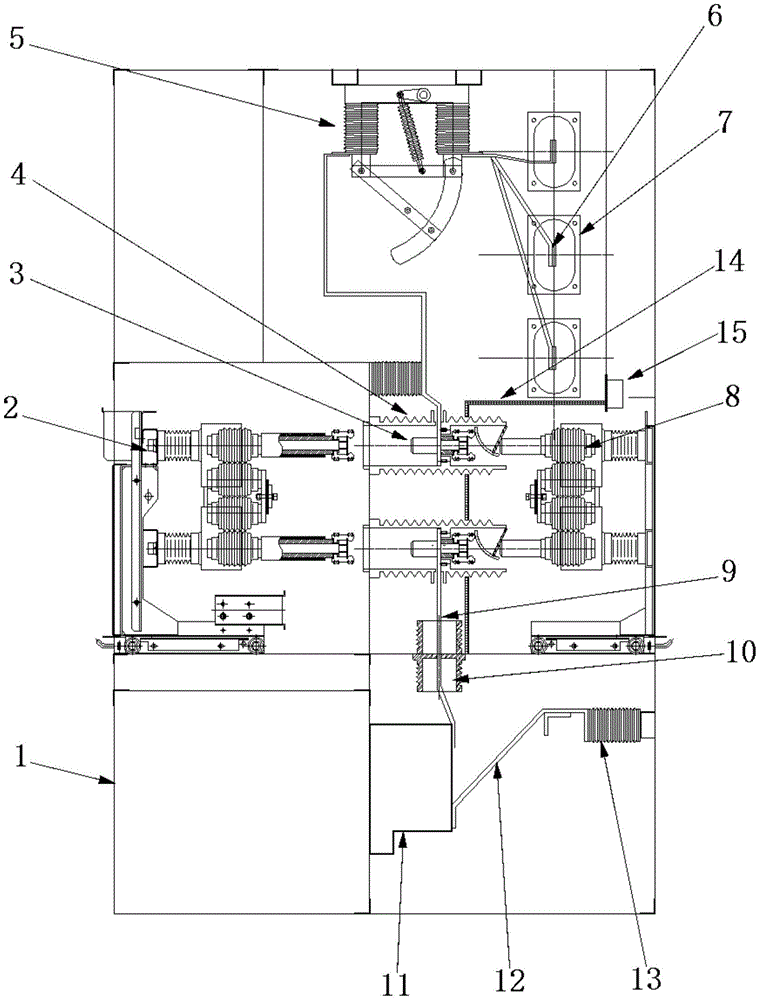
图1是本实用新型的主视图。Figure 1 is a front view of the present invention.
图2是本实用新型的侧视图。Figure 2 is a side view of the present invention.
图3是本实用新型的保护方案图。Fig. 3 is the protection scheme diagram of the present utility model.
附图标记说明:柜体装配1、断路器手车2、一次静触头3、触头盒4、上隔离开关5、主母线与支母线装配6、母线套管7、手车式多功能保护装置8、导通母线9、下隔离开关10、互感器11、固定接地母线装配12、传感器13、绝缘板14、航空插座15。Description of reference numerals: cabinet assembly 1,
具体实施方式Detailed ways
下面将结合本实用新型实施例中的附图,对本实用新型实施例中的技术方案进行清楚、完整地描述,显然,所描述的实施例仅仅是本实用新型一部分实施例,而不是全部的实施例。基于本实用新型中的实施例,本领域普通技术人员在没有做出创造性劳动前提下所获得的所有其他实施例,都属于本实用新型保护的范围。The technical solutions in the embodiments of the present utility model will be clearly and completely described below with reference to the accompanying drawings in the embodiments of the present utility model. Obviously, the described embodiments are only a part of the embodiments of the present utility model, rather than all the implementations. example. Based on the embodiments of the present invention, all other embodiments obtained by those of ordinary skill in the art without creative work fall within the protection scope of the present invention.
如图1和图2所示,本实用新型的上下隔离开关保护柜,是由柜体装配1、断路器手车2、一次静触头3、触头盒4、上隔离开关5、主母线与支母线装配6、母线套管7、手车式多功能保护装置8、导通母线9、下隔离开关10、互感器11、固定接地母线装配12、传感器13、绝缘板14、航空插座15组成。As shown in Figures 1 and 2, the upper and lower isolation switch protection cabinet of the present invention is composed of cabinet assembly 1,
参考图1和图2,本实用新型的动作关联为:柜体装配1为该柜的主体部分架构,柜体装配1内部主要由主母线与支母线装配6连接上隔离开关5再连接一次静触头3与断路器手车2再与导通母线9、下隔离开关10、互感器11、固定接地母线装配12、传感器13连接形成一个完整的电流、电压通路,并将手车式多功能保护装置8与断路器手车2进行并联,手车式多功能保护装置8与断路器手车2均可以推进推出,触头盒4是为了保护一次静触头3与断路器手车2的连接处绝缘等级要求所设,母线套管7是保护主母线与支母线装配6之绝缘等级要求所设,绝缘板14设置在手车式多功能保护装置8与其他装置之间,将手车式多功能保护装置8围起来,绝缘板14连接航空插座15。图3是本实用新型的保护方案图,示出了本实用新型的结构。Referring to Figure 1 and Figure 2, the action of the present utility model is related as follows: the cabinet assembly 1 is the main part of the cabinet, and the interior of the cabinet assembly 1 is mainly connected by the main busbar and the branch busbar assembly 6. The
参考图1和图2,本实用新型的保护原理为:该柜与其它母线柜并列排列,故该整个母线上出现各种过电压升高时,通过主母线与支母线装配6对一次静触头3与断路器手车2再与导通母线9、互感器11、固定接地母线装配12、传感器13形成一个完整的电流、电压通路,由手车式多功能保护装置8进行直接吸收并经过导通母线9、互感器11、固定接地母线装配12进入大地,体现了本实用新型的快速吸收过电压的功能及保护其它设备的安全。同时由手车式多功能保护装置8对断路器手车2并列之柜的断路器有效保护,确保断路器手车2大容量有效开断之效果。由于主母线与支母线装配6从上面通过该柜向下供电,在断路器前面设置一组上隔离开关5与电源隔离,并在在断路器后面设置一组下隔离开关10与负载隔离,建立可靠的绝缘间隙,将需要检修的设备或线路与电源用明显断开点隔开,以保证检修人员和设备的安全。绝缘板14和航空插座15的设置起到了对手车式多功能保护装置8建立可靠绝缘,以保证检修人员和设备的安全的作用。Referring to Figures 1 and 2, the protection principle of the present invention is as follows: the cabinet is arranged side by side with other busbar cabinets, so when various overvoltage rises occur on the entire busbar, 6 pairs of primary static contacts are assembled through the main busbar and the branch busbar The
上述的对实施例的描述是为便于该技术领域的普通技术人员能理解和应用本专利。熟悉本领域技术的人员显然可以容易地对这些实施例做出各种修改,并把在此说明的一般原理应用到其他实施例中而不必经过创造性的劳动。因此,本实用新型不限于这里的实施例,本领域技术人员根据本实用新型的揭示,不脱离本实用新型范畴所做出的改进和修改都应该在本实用新型的保护范围之内。The above description of the embodiments is for the convenience of those skilled in the art to understand and apply the present patent. It will be apparent to those skilled in the art that various modifications to these embodiments can be readily made, and the generic principles described herein can be applied to other embodiments without inventive step. Therefore, the present invention is not limited to the embodiments herein, and improvements and modifications made by those skilled in the art according to the disclosure of the present invention without departing from the scope of the present invention should all fall within the protection scope of the present invention.
Claims (5)
Priority Applications (1)
| Application Number | Priority Date | Filing Date | Title |
|---|---|---|---|
| CN201822245729.1U CN210016170U (en) | 2018-12-29 | 2018-12-29 | A kind of upper and lower isolation switch protection cabinet |
Applications Claiming Priority (1)
| Application Number | Priority Date | Filing Date | Title |
|---|---|---|---|
| CN201822245729.1U CN210016170U (en) | 2018-12-29 | 2018-12-29 | A kind of upper and lower isolation switch protection cabinet |
Publications (1)
| Publication Number | Publication Date |
|---|---|
| CN210016170U true CN210016170U (en) | 2020-02-04 |
Family
ID=69312143
Family Applications (1)
| Application Number | Title | Priority Date | Filing Date |
|---|---|---|---|
| CN201822245729.1U Active CN210016170U (en) | 2018-12-29 | 2018-12-29 | A kind of upper and lower isolation switch protection cabinet |
Country Status (1)
| Country | Link |
|---|---|
| CN (1) | CN210016170U (en) |
Cited By (1)
| Publication number | Priority date | Publication date | Assignee | Title |
|---|---|---|---|---|
| CN119834086A (en) * | 2025-03-18 | 2025-04-15 | 河南泰隆电力设备股份有限公司 | A compact center-mounted ring main unit |
-
2018
- 2018-12-29 CN CN201822245729.1U patent/CN210016170U/en active Active
Cited By (1)
| Publication number | Priority date | Publication date | Assignee | Title |
|---|---|---|---|---|
| CN119834086A (en) * | 2025-03-18 | 2025-04-15 | 河南泰隆电力设备股份有限公司 | A compact center-mounted ring main unit |
Similar Documents
| Publication | Publication Date | Title |
|---|---|---|
| CN103337852B (en) | A kind of direct current network breaking device | |
| CN106415960A (en) | Circuit breaker with arc eliminator and power receiving/distributing equipment using same | |
| CN115425567A (en) | High-safety SF6 full-insulation compact ring main unit | |
| CN203180518U (en) | Intelligent switch arc-extinguishing and overvoltage-protecting device | |
| CN201004553Y (en) | Arc over voltage limit for power transmission and distribution system and integrated device for small current grounding and line selection | |
| CN105794059B (en) | Switchgear with busbar-side voltage transformers or surge arresters | |
| CN201498291U (en) | Detachable lightning arrester | |
| CN102290805A (en) | Electric arc grounding overvoltage limiting device applied to medium-voltage distribution system | |
| CN210016092U (en) | A fixed upper and lower isolation switch protection cabinet | |
| CN210016165U (en) | Upper isolating switch protection cabinet | |
| CN210016099U (en) | A fixed upper isolation switch protection cabinet | |
| CN210693223U (en) | A voltage transformer isolation combined device applied to non-power-off operation | |
| CN209329537U (en) | Disconnecting switch protection cabinets on a kind of handcart-type | |
| CN209329536U (en) | A kind of handcart-type protection cabinets | |
| CN104426088A (en) | Voltage transformer handcart | |
| KR101324731B1 (en) | Load breaker switchgear and package panel switchgear having the same | |
| CN206451650U (en) | A kind of breaker | |
| CN206992000U (en) | A kind of environmentally friendly cabinet breaker | |
| CN209329423U (en) | A kind of large capacity cut-offs protection cabinets | |
| CN205582804U (en) | A power isolating switch with rain and lightning protection function | |
| CN204304424U (en) | A kind of single-phase earthing superpotential transfer restraint device | |
| CN205543927U (en) | Single -phase double break mouth SF6 circuit breaker of railway | |
| CN214099488U (en) | Self-driven vacuum double-arc-extinguishing-chamber cut-off circuit breaker | |
| CN213484506U (en) | A neutral fault protector | |
| CN202564798U (en) | Intelligent harmonic and arc extinction switch cabinet |
Legal Events
| Date | Code | Title | Description |
|---|---|---|---|
| GR01 | Patent grant | ||
| GR01 | Patent grant | ||
| CP01 | Change in the name or title of a patent holder | ||
| CP01 | Change in the name or title of a patent holder |
Address after: South District of 11 Third Building, 2285 Tingwei Highway, Jinshan District, Shanghai, 200540 Patentee after: Shanghai Shuying Technology Co.,Ltd. Address before: South District of 11 Third Building, 2285 Tingwei Highway, Jinshan District, Shanghai, 200540 Patentee before: SHANGHAI SUIN ELECTRIC CO.,LTD. |
|
| EE01 | Entry into force of recordation of patent licensing contract | ||
| EE01 | Entry into force of recordation of patent licensing contract |
Contract record no.: X2026980004921 Denomination of utility model: A circuit breaker cabinet with upper and lower isolation switches Granted publication date: 20200204 License type: Common License Record date: 20260410 |