CN210002790U - skirting line system convenient to disassemble and assemble - Google Patents
skirting line system convenient to disassemble and assemble Download PDFInfo
- Publication number
- CN210002790U CN210002790U CN201920359076.1U CN201920359076U CN210002790U CN 210002790 U CN210002790 U CN 210002790U CN 201920359076 U CN201920359076 U CN 201920359076U CN 210002790 U CN210002790 U CN 210002790U
- Authority
- CN
- China
- Prior art keywords
- angle
- plate
- skirting line
- vertical plate
- riser
- Prior art date
- Legal status (The legal status is an assumption and is not a legal conclusion. Google has not performed a legal analysis and makes no representation as to the accuracy of the status listed.)
- Active
Links
Images


Abstract
The utility model relates to a skirting line system convenient to dismouting belongs to assembly type building technical field, specifically including installing the skirting line panel on the assembly type wall body, the skirting line panel is fixed on the assembly type wall body through a plurality of connections fastener, reentrant corner position between the skirting line panel is provided with the reentrant corner connecting piece, the reentrant corner position between the skirting line panel is provided with the reentrant corner connecting piece, it mainly by bottom plate to connect the fastener, riser, second riser and third riser constitute, riser, second riser and third riser are fixed in proper order on bottom plate, assembly type wall body cartridge is between riser and second riser, the bottom of skirting line panel is vertical upwards to be provided with the draw-in groove, the back of skirting line panel is provided with the second draw-in groove, the third riser cartridge is in , and the second riser card is in the second draw-in groove, the utility model discloses simple structure, easy dismounting, and it is apparent pleasing to the eye, it is fixed reliable.
Description
Technical Field
The utility model relates to a skirting line system of kinds of dismouting of being convenient for belongs to assembly type structure technical field.
Background
With , the decoration assembly is rapidly developed, and the functions of rapid installation, convenient disassembly, no mutual influence between parts and beauty and practicability are marks indicating whether the assembly process is mature.
The skirting line is arranged at the joint of the floor and the wall corner in the house decoration process, so that the combination firmness degree between the wall and the floor can be enhanced, the deformation of the wall is reduced, and the damage of the wall caused by external force collision is avoided; and the skirting line can cover the gap at the joint of the floor and the wall, and the gap can provide space for the wet expansion and the dry shrinkage of the floor. In addition, the skirting line is easy to scrub, and if dirty water is splashed on the mopping floor, the scrubbing is very convenient. Besides the function of protecting the wall surface, the skirting line also accounts for a certain proportion of the beautiful appearance of the house.
To the assembled wall, use present skirting line design, fix the skirting line in the junction of wall and floor, when causing the change assembled wallboard, the skirting line dismouting is inconvenient, and the dismouting is wasted time and energy, and the construction cycle is long, and work efficiency is low.
SUMMERY OF THE UTILITY MODEL
For solving the technical problem that prior art exists, the utility model provides an kinds of simple structure, easy dismounting to the outward appearance is pleasing to the eye, fixed reliable skirting line system of the dismouting of being convenient for.
For realizing above-mentioned mesh, the utility model discloses the skirting line system of kinds of dismouting of being convenient for, including installing the skirting line panel on the assembled wall body, the skirting line panel is fixed on the assembled wall body through a plurality of connection fasteners, reentrant corner position between the skirting line panel is provided with the reentrant corner connecting piece, the reentrant corner position between the skirting line panel is provided with the reentrant corner connecting piece, it connects the fastener and adopts aluminum alloy material or plastic-aluminum material to make, and mainly comprises bottom plate, riser, second riser and third riser, riser, second riser and third riser are fixed in proper order on bottom plate, assembled wall body cartridge is between riser and second riser, the bottom of skirting line panel is vertical upwards to be provided with draw-in groove, the back of skirting line panel is provided with the second draw-in groove, the third cartridge is in , and the second draw-in groove card is in the second riser.
Preferably, the bottom plate, riser, second riser and third riser are arranged, the heights of the riser, second riser and third riser decrease in sequence, and the height of the riser is the same as the height of the skirting line panel.
Preferably, the reentrant corner connecting piece mainly comprises mounting and covering, mounting adopts aluminum alloy material or aluminum-plastic material to make, and mainly comprises second bottom plate, right-angle board, second right-angle board and third right-angle board, right-angle board, second right-angle board and third right-angle board are fixed on the second bottom plate in proper order, the reentrant corner position cartridge of assembled wall body is between right-angle board, second right-angle board, the covering is square column structure, and the top of this square column structure is provided with the cambered surface, the bottom of square column structure is provided with the right angle slot, just the both sides of right angle slot are run through the side of square column structure, covering cartridge is between second right-angle board and third right-angle board, and the third right-angle board cartridge is in the right angle slot.
Preferably, the heights of the right-angle plate, the second right-angle plate and the third right-angle plate are sequentially reduced, and the height of the second right-angle plate is the same as that of the covering part.
Preferably, the external corner connecting piece mainly comprises second mounting and right angle covering, the second mounting adopts aluminum alloy material or aluminum-plastic material to make, and mainly comprises third bottom plate, fourth right-angle board, fifth right-angle board and sixth right-angle board are fixed on the third bottom plate in proper order, the external corner position cartridge of assembled wall body is between fourth right-angle board, fifth right-angle board, the top of right angle covering is provided with the cambered surface, the bottom of right angle covering is provided with the right angle slot, just the both sides of right angle slot are run through the side of right angle covering, the right angle covering cartridge is between fifth right-angle board and sixth right-angle board, just sixth right angle board cartridge is in the right angle slot.
Preferably, the heights of the fourth rectangular plate, the fifth rectangular plate and the sixth rectangular plate are sequentially reduced, and the heights of the fifth rectangular plate and the right-angle covering piece are the same.
Compared with the prior art, the utility model has the following technical effects of the utility model discloses simple structure, easy dismounting, adopt between the connection fastener with the skirting line panel card in assembled wall body bottom, utilize the assembled wall body to compress tightly the connection fastener, it is fixed reliable to guarantee to connect the fastener, stability is good, the reentrant corner and the external corner position of the assembled wall body all adopt reentrant corner connecting piece and external corner connecting piece to connect simultaneously, then utilize the assembled wall body to compress tightly fixedly, the reentrant corner connecting piece, the external corner connecting piece is disconnected with the skirting line panel, when decorating wall body demolish or change, the skirting line panel can be demolishd along with assembled wall body , do not need independent dismantlement, construction speed is fast, the cycle is short, and utilize the fastener to connect, easy dismounting, can dismantle fast, high work efficiency.
Drawings
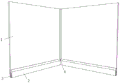
Fig. 1 is a schematic structural diagram of the present invention.
Fig. 2 is a schematic structural view of the middle connection clip of the present invention.
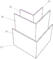
Fig. 3 is a schematic structural view of the female corner connector of the present invention.
Fig. 4 is a schematic structural view of an th fixing member according to the present invention.
Fig. 5 is a schematic structural view of a th covering member according to the present invention.
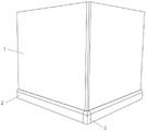
Fig. 6 is a schematic structural view of the middle external corner connector of the present invention.
Fig. 7 is a schematic structural diagram of a second fixing member according to the present invention.
Fig. 8 is a schematic structural view of the middle right-angle covering member of the present invention.
Fig. 9 is a schematic structural view of the back of the middle right-angle covering member of the present invention.
Detailed Description
In order to make the technical problems, technical solutions and advantages of the present invention to be solved clearer, the present invention is described in detail below with reference to the accompanying drawings and embodiments in steps.
As shown in fig. 1, 2 and 6, skirting line systems convenient to disassemble and assemble comprise a skirting line panel 2 installed on an assembly wall 1, the skirting line panel 2 is fixed on the assembly wall 1 through a plurality of connecting fasteners 3, a reentrant corner connector 4 is arranged at a reentrant corner position between the skirting line panels 2, a reentrant corner connector 5 is arranged at a reentrant corner position between the skirting line panels 2, the connecting fasteners 3 mainly comprise a bottom plate 6, a vertical plate 7, a second vertical plate 8 and a third vertical plate 9, the vertical plate 7, the second vertical plate 8 and the third vertical plate 9 are sequentially fixed on the bottom plate 6, the assembly wall 1 is inserted between a vertical plate 7 and the second vertical plate 8, a clamping groove 10 is vertically arranged at the bottom of the skirting line panel 2, a second clamping groove 11 is arranged at the back of the skirting line panel 2, the third vertical plate 9 is inserted in a clamping groove 10, and the second vertical plate 7 is clamped in the second clamping groove 11.
The utility model discloses well skirting line panel 2 directly fixes the bottom at the assembled wall body through a plurality of connecting fastener 3, the assembled wall body is compressed tightly and is connected the fastener, and it adopts aluminum alloy material or aluminum-plastic material to make to connect the fastener, high strength, can guarantee that skirting line panel is fixed reliable, set up draw-in groove 10 on the skirting line panel, second draw-in groove 11, draw-in groove 10 is used for the card on connecting fastener 3, second draw-in groove 11 is used for blocking second riser 7, also can guarantee that skirting line panel and assembled wall body closely laminate, bottom plate 6, riser 7, second riser 8 and third riser 9 body set up, riser 7, the height of second riser 8 and third riser 9 reduces in proper order, the height of riser 7 is the same with the height of skirting line panel 2, can guarantee that the skirting line panel has sufficient fixed height and structural strength like this, guarantee that the skirting line panel is fixed reliable outward appearance, simultaneously can also beautifully.
As shown in fig. 3 to 5, the female connector 4 is mainly composed of -th fastener 12 and -th covering element 13, -th fastener 12 is mainly composed of second bottom plate 14, -th right-angle plate 15, second right-angle plate 16 and third right-angle plate 17, -th right-angle plate 15, second right-angle plate 16 and third right-angle plate 17 are sequentially fixed on second bottom plate 14, the female position of the assembled wall 1 is inserted between -th right-angle plate 15 and second right-angle plate 16, -th covering element 13 is a square column structure, the top of the square column structure is provided with a cambered surface, the bottom of the square column structure is provided with right-angle slots 18, and both sides of the right-angle slots 18 penetrate through the side surfaces of the square column structure, -th covering element 13 is inserted between the second right-angle plate 16 and third right-angle plate 17, and the third right-angle plate 17 is inserted in the right-angle slots 18-angle connector 4 is also fixed at the female position of the assembled wall, the female connector is pressed tightly by a kick line, because the kick line is connected with the second right-angle plate 16, the third right-angle plate 17, the male connector 13, the male connector has enough strength to ensure that the male connector 13 can be installed and the male connector 13, and the male connector has enough strength of the male connector 16, and the male connector can be installed with the male connector, thereby ensuring that the male connector 16, the male connector has enough strength of the male connector 16, the male connector 13, the male connector, the male.
As shown in fig. 6 to 9, the external corner connector 5 mainly comprises a second fixing member 19 and a right-angle covering member 20, the second fixing member 19 mainly comprises a third bottom plate 21, a fourth right-angle plate 22, a fifth right-angle plate 23 and a sixth right-angle plate 24, the fourth right-angle plate 22, the fifth right-angle plate 23 and the sixth right-angle plate 24 are sequentially fixed on the third bottom plate 21, the external corner position of the assembled wall body 1 is inserted between the fourth right-angle plate 22 and the fifth right-angle plate 23, the top of the right-angle covering member 20 is provided with an arc surface, the bottom of the right-angle covering member 20 is provided with a right-angle slot, the two sides of the right-angle slot penetrate through the side surface of the right-angle covering member, the right-angle covering member is inserted between the fifth right-angle plate 23 and the sixth right-angle plate 24. The external corner connecting piece 5 is also fixed at the external corner position of the assembled wall body and is pressed tightly by the assembled wall body. Similarly, because the skirting line panel adopts and connects the fastener to fix, skirting line panel tip has sufficient intensity, need not fix with external corner connecting piece 5, and independent dismouting can be carried out to skirting line panel, reentrant corner connecting piece 4 like this, guarantees easy dismounting. The heights of the fourth, fifth and sixth squaring panels 22, 23, 24 decrease in sequence, and the fifth squaring panel 23 is the same as the height of the right angle covering 20. Therefore, the right-angle covering piece 20 can be guaranteed to have enough fixed height and structural strength, the right-angle covering piece 20 is guaranteed to be fixed reliably, and meanwhile, the appearance is attractive.
The foregoing is considered as illustrative and not restrictive of the preferred embodiments of the invention, and any modifications, equivalents and improvements made within the spirit and principles of the invention are intended to be included within the scope of the invention.
Claims (6)
- The skirting line system convenient to disassemble and assemble is characterized in that the skirting line panels are fixed on an assembled wall body through a plurality of connecting clamping pieces, an internal corner connecting piece is arranged at an internal corner position between the skirting line panels, an external corner connecting piece is arranged at an external corner position between the skirting line panels, the connecting clamping pieces are made of aluminum alloy materials or aluminum-plastic materials and mainly comprise a th bottom plate, a th vertical plate, a second vertical plate and a third vertical plate, the th vertical plate, the second vertical plate and the third vertical plate are sequentially fixed on a th bottom plate, the assembled wall body is inserted between a th vertical plate and the second vertical plate, a th clamping groove is vertically arranged upwards at the bottom of the skirting line panel, a second clamping groove is arranged at the back of the skirting line panel, the third vertical plate is inserted in the th clamping groove, and the second vertical plate is clamped in the second clamping groove.
- 2. The skirting line system convenient to disassemble and assemble according to claim 1, wherein the bottom plate, th vertical plate, the second vertical plate and the third vertical plate are arranged, the heights of the th vertical plate, the second vertical plate and the third vertical plate are sequentially reduced, and the height of the th vertical plate is the same as the height of the skirting line panel.
- 3. The skirting line system convenient to disassemble and assemble according to claim 1, wherein the reentrant corner connector mainly comprises a fixing member and a covering member, the fixing member is made of aluminum alloy or aluminum plastic, and mainly comprises a second bottom plate, a right-angle plate, a second right-angle plate and a third right-angle plate, the right-angle plate, the second right-angle plate and the third right-angle plate are sequentially fixed on the second bottom plate, the reentrant corner position of the assembly wall body is inserted between the right-angle plate and the second right-angle plate, the covering member is a square column structure, the top of the square column structure is provided with an arc surface, the bottom of the square column structure is provided with right-angle insertion grooves, two sides of the right-angle insertion grooves penetrate through the side surfaces of the square column structure, the is inserted between the second right-angle plate and the third right-angle plate, and the third right-angle plate is inserted in the right-angle insertion grooves.
- 4. The skirting line system convenient for disassembly and assembly as claimed in claim 3, wherein the heights of said L-panels, said second L-panel and said third L-panel decrease in sequence, and said second L-panel is the same as the height of said covering member.
- 5. The skirting line system convenient to disassemble and assemble according to claim 1, wherein the external corner connector mainly comprises a second fixing member and a right-angle covering member, the second fixing member is made of aluminum alloy or aluminum-plastic material and mainly comprises a third bottom plate, a fourth right-angle plate, a fifth right-angle plate and a sixth right-angle plate, the fourth right-angle plate, the fifth right-angle plate and the sixth right-angle plate are sequentially fixed on the third bottom plate, the external corner position of the assembly wall body is inserted between the fourth right-angle plate and the fifth right-angle plate, the top of the right-angle covering member is provided with an arc surface, the bottom of the right-angle covering member is provided with a right-angle slot, the two sides of the right-angle slot penetrate through the side surface of the right-angle covering member, the right-angle covering member is inserted between the fifth right-angle plate and the sixth right-angle plate, and the sixth right-angle plate is inserted in.
- 6. The skirting line system convenient for disassembly and assembly as claimed in claim 5, wherein the heights of said fourth, fifth and sixth squaring panels decrease in sequence, and said fifth squaring panel is the same as the height of the right angle covering piece.
Priority Applications (1)
| Application Number | Priority Date | Filing Date | Title |
|---|---|---|---|
| CN201920359076.1U CN210002790U (en) | 2019-03-21 | 2019-03-21 | skirting line system convenient to disassemble and assemble |
Applications Claiming Priority (1)
| Application Number | Priority Date | Filing Date | Title |
|---|---|---|---|
| CN201920359076.1U CN210002790U (en) | 2019-03-21 | 2019-03-21 | skirting line system convenient to disassemble and assemble |
Publications (1)
| Publication Number | Publication Date |
|---|---|
| CN210002790U true CN210002790U (en) | 2020-01-31 |
Family
ID=69301835
Family Applications (1)
| Application Number | Title | Priority Date | Filing Date |
|---|---|---|---|
| CN201920359076.1U Active CN210002790U (en) | 2019-03-21 | 2019-03-21 | skirting line system convenient to disassemble and assemble |
Country Status (1)
| Country | Link |
|---|---|
| CN (1) | CN210002790U (en) |
-
2019
- 2019-03-21 CN CN201920359076.1U patent/CN210002790U/en active Active
Similar Documents
| Publication | Publication Date | Title |
|---|---|---|
| CN105908928A (en) | Wall frame internal corner clamping system | |
| CN211286152U (en) | Multipurpose closing line structure | |
| CN210002790U (en) | skirting line system convenient to disassemble and assemble | |
| CN203834874U (en) | Installation buckle piece of decorative sheets at internal corner of wall | |
| CN110565846A (en) | Assembled wallboard hangs structure | |
| CN214034523U (en) | Buckle wallboard of installation direction | |
| CN210857799U (en) | Internal corner assembly | |
| CN210918059U (en) | Functional metal convex decorative profile connecting device for interior decorative wall panel wall | |
| JP5967770B2 (en) | Baseboard mounting structure | |
| CN112211359A (en) | Architectural decoration system | |
| CN215888856U (en) | Furred ceiling decorative board piece structure | |
| CN211648701U (en) | Invisible self-plugging connecting piece for furniture | |
| CN212583136U (en) | Novel baseboard mosaic structure | |
| CN211736154U (en) | Mounting structure of decorative plate at splicing position | |
| CN212026941U (en) | Glue-free connecting decorative plate | |
| CN109372229B (en) | Combined fast-assembling buckle skirting line | |
| CN215484286U (en) | Double-sided wood-plastic wallboard and double-sided wood-plastic wallboard mounting structure | |
| CN217734716U (en) | But be applied to quick assembly disassembly skirting line in ward | |
| CN220133326U (en) | Assembled bathroom external corner mounting structure | |
| CN219671685U (en) | Lap joint piece for lap joint of independent frame type bathroom suspended ceiling | |
| CN214169712U (en) | Architectural decoration system | |
| CN210316299U (en) | Assembled fitment shingle nail structure | |
| CN215802951U (en) | Furred ceiling moulding and installation component thereof | |
| CN203028746U (en) | Combined type photo frame | |
| CN211775294U (en) | Internal corner structure of decorative wall |
Legal Events
| Date | Code | Title | Description |
|---|---|---|---|
| GR01 | Patent grant | ||
| GR01 | Patent grant |