CN209997799U - Ash cleaning device for electric dust collector - Google Patents
Ash cleaning device for electric dust collector Download PDFInfo
- Publication number
- CN209997799U CN209997799U CN201920142390.4U CN201920142390U CN209997799U CN 209997799 U CN209997799 U CN 209997799U CN 201920142390 U CN201920142390 U CN 201920142390U CN 209997799 U CN209997799 U CN 209997799U
- Authority
- CN
- China
- Prior art keywords
- dust
- dust collecting
- pipe
- driving
- ash
- Prior art date
- Legal status (The legal status is an assumption and is not a legal conclusion. Google has not performed a legal analysis and makes no representation as to the accuracy of the status listed.)
- Expired - Fee Related
Links
- 239000000428 dust Substances 0.000 title claims abstract description 220
- 238000004140 cleaning Methods 0.000 title claims description 27
- 239000012717 electrostatic precipitator Substances 0.000 claims abstract description 19
- 239000011810 insulating material Substances 0.000 claims description 4
- UGFAIRIUMAVXCW-UHFFFAOYSA-N Carbon monoxide Chemical compound [O+]#[C-] UGFAIRIUMAVXCW-UHFFFAOYSA-N 0.000 abstract description 10
- 239000003546 flue gas Substances 0.000 abstract description 10
- 238000000746 purification Methods 0.000 abstract description 2
- 238000010521 absorption reaction Methods 0.000 abstract 1
- 239000000779 smoke Substances 0.000 abstract 1
- 238000004891 communication Methods 0.000 description 7
- 238000010586 diagram Methods 0.000 description 7
- 230000000694 effects Effects 0.000 description 7
- 238000000034 method Methods 0.000 description 7
- 230000008569 process Effects 0.000 description 4
- 238000009434 installation Methods 0.000 description 2
- 230000009471 action Effects 0.000 description 1
- 230000009286 beneficial effect Effects 0.000 description 1
- 230000005540 biological transmission Effects 0.000 description 1
- 230000001680 brushing effect Effects 0.000 description 1
- 230000008021 deposition Effects 0.000 description 1
- 230000005684 electric field Effects 0.000 description 1
- 239000003517 fume Substances 0.000 description 1
- 238000012986 modification Methods 0.000 description 1
- 230000004048 modification Effects 0.000 description 1
- 239000012716 precipitator Substances 0.000 description 1
- 238000007789 sealing Methods 0.000 description 1
Images


Landscapes
- Cleaning In General (AREA)
Abstract
Description
技术领域technical field
本实用新型涉及工业烟尘净化技术领域,特别涉及一种用于电除尘器的清灰装置。The utility model relates to the technical field of industrial fume and dust purification, in particular to a dust cleaning device for an electric precipitator.
背景技术Background technique
电除尘器是一种分离烟气中粉尘的设备。通常电除尘器利用高压电场让烟气发生电离,使得烟气中的粉尘携带电荷,通过电除尘器中的阳极板或阴极板将携带电荷的粉尘吸附在表面,然后使用清灰装置将粉尘从阳极板或阴极板的表面清除。An electrostatic precipitator is a device that separates dust from flue gas. Usually, the electrostatic precipitator uses a high-voltage electric field to ionize the flue gas, so that the dust in the flue gas carries electric charges. Surface removal of anode or cathode plates.
目前的清灰装置通常包括毛刷、驱动组件和收集袋,毛刷设置在电除尘器中的阳极板或阴极板的侧面上,通过驱动组件驱动毛刷沿着阳极板或阴极板的侧面往复刷动,以使得从阳极板或阴极板上脱落的粉尘落入位于毛刷下方的收集袋内。The current cleaning device usually includes a brush, a drive assembly and a collection bag. The brush is arranged on the side of the anode plate or the cathode plate in the electrostatic precipitator, and the brush is driven to reciprocate along the side of the anode plate or the cathode plate through the drive assembly. The brush moves so that the dust shed from the anode or cathode plate falls into the collection bag located under the brush.
然而,现有的清灰装置使用收集袋收集自行脱落的粉尘的方式属于被动收尘,在收尘的过程中会存在部分粉尘未被收集袋所收集,因此存在清灰不彻底的问题。同时,未被收集的粉尘在烟气的气流影响下会重新返回烟气中,产生二次扬尘,导致电除尘器的烟气排放口处的粉尘浓度过大,降低电除尘器的除尘效率。However, the existing dust cleaning device uses a collection bag to collect the dust that falls off by itself, which belongs to passive dust collection. During the dust collection process, some dust may not be collected by the collection bag, so there is a problem of incomplete dust removal. At the same time, the uncollected dust will return to the flue gas under the influence of the airflow of the flue gas, resulting in secondary dust, resulting in excessive dust concentration at the flue gas discharge port of the electrostatic precipitator and reducing the dust removal efficiency of the electrostatic precipitator.
实用新型内容Utility model content
本实用新型实施例提供了一种用于电除尘器的清灰装置,能彻底清灰,避免粉尘重新返回烟气内而产生二次扬尘的问题。所述技术方案如下:The embodiment of the present utility model provides a dust cleaning device for an electrostatic precipitator, which can completely remove dust and avoid the problem of dust returning to the flue gas to generate secondary dust. The technical solution is as follows:
一方面,本实用新型实施例提供了一种用于电除尘器的清灰装置,所述清灰装置包括:集尘管,外壁上设有吸尘孔,除尘刷,位于所述集尘管的外壁,用于驱动所述集尘管移动的驱动组件,排风机的抽风口与所述集尘管连通。On the one hand, an embodiment of the present utility model provides a dust cleaning device for an electrostatic precipitator. The dust cleaning device includes: a dust collecting pipe, an outer wall is provided with a dust suction hole, and a dust removal brush is located in the dust collecting pipe The outer wall of the dust collector is used to drive the moving drive assembly of the dust collecting pipe, and the air outlet of the exhaust fan is communicated with the dust collecting pipe.
在本实用新型实施例的一种实现方式中,所述集尘管的数量为两个,两个所述集尘管平行间隔分布,所述除尘刷位于两个所述集尘管之间。In an implementation manner of the embodiment of the present invention, the number of the dust collecting pipes is two, the two dust collecting pipes are distributed in parallel and spaced apart, and the dust removing brush is located between the two dust collecting pipes.
在本实用新型实施例的另一种实现方式中,所述清灰装置还包括安装架,两个所述集尘管的一端均与所述安装架连接。In another implementation manner of the embodiment of the present invention, the dust cleaning device further includes a mounting bracket, and one ends of the two dust collecting pipes are both connected to the mounting bracket.
在本实用新型实施例的另一种实现方式中,所述清灰装置还包括连通管,两个所述集尘管的另一端与所述连通管连通。In another implementation manner of the embodiment of the present invention, the dust cleaning device further includes a communication pipe, and the other ends of the two dust collecting pipes are communicated with the communication pipe.
在本实用新型实施例的另一种实现方式中,所述除尘刷的两侧均设有所述吸尘孔。In another implementation manner of the embodiment of the present invention, the dust suction holes are provided on both sides of the dust removal brush.
在本实用新型实施例的另一种实现方式中,两个所述吸尘孔的圆心分别与所述集尘管的中轴线的连线的夹角为40°至90°。In another implementation manner of the embodiment of the present invention, the included angle between the center of the two dust suction holes and the line connecting the central axis of the dust collecting pipe is 40° to 90°.
在本实用新型实施例的另一种实现方式中,所述吸尘孔有多个,多个所述吸尘孔沿所述集尘管的轴向分布。In another implementation manner of the embodiment of the present invention, there are a plurality of the dust suction holes, and the plurality of the dust suction holes are distributed along the axial direction of the dust collecting pipe.
在本实用新型实施例的另一种实现方式中,所述清灰装置还包括连接管道,所述连接管道的一端与所述排风机的抽风口连通,所述连接管道的另一端与所述集尘管连通,所述连接管道为柔性管。In another implementation manner of the embodiment of the present invention, the ash cleaning device further includes a connecting pipe, one end of the connecting pipe is communicated with the air outlet of the exhaust fan, and the other end of the connecting pipe is connected to the air outlet of the exhaust fan. The dust collecting pipes are connected, and the connecting pipes are flexible pipes.
在本实用新型实施例的另一种实现方式中,所述除尘刷的刷毛为绝缘材料。In another implementation manner of the embodiment of the present invention, the bristles of the dust removal brush are insulating materials.
在本实用新型实施例的另一种实现方式中,所述驱动组件包括:驱动电机、驱动齿轮和驱动齿条,所述驱动齿轮套装在所述驱动电机的输出轴上,所述驱动齿条与所述驱动齿轮啮合,所述集尘管与所述驱动齿条连接。In another implementation manner of the embodiment of the present invention, the drive assembly includes: a drive motor, a drive gear, and a drive rack, the drive gear is sleeved on the output shaft of the drive motor, and the drive rack Meshing with the driving gear, the dust collecting pipe is connected with the driving rack.
本实用新型实施例提供的技术方案带来的有益效果是:The beneficial effects brought by the technical solutions provided by the embodiments of the present utility model are:
本实用新型实施例在集尘管的外壁上设置了除尘刷,在使用时通过控制驱动组件使得集尘管在电除尘器的阴极板或阳极板的侧面上往复移动,并通过除尘刷使阴极板或阳极板上沉积的粉尘与阴极板或阳极板剥离,从而可以全面地将吸附在阴极板或阳极板上的粉尘刷落,同时集尘管的外壁上还设有吸尘孔,且集尘管的内部空间可以通过排风机将抽空,使得集尘管内保持一定真空度,因此通过吸尘孔就可以将从阴极板或阳极板剥离的粉尘吸入集尘管内,并最终通过集尘管排出,由于通过具有真空度的集尘管可以将集尘管附近的粉尘全吸入其中,相较于现有的被动收尘方式,本实用新型收尘效果更好且更彻底,因此也能有效地避免粉尘重新返回烟气内,产生二次扬尘。In the embodiment of the present utility model, a dust-removing brush is arranged on the outer wall of the dust-collecting tube. When in use, the dust-collecting tube is reciprocated on the side of the cathode plate or the anode plate of the electrostatic precipitator by controlling the driving component, and the cathode is moved by the dust-removing brush. The dust deposited on the plate or anode plate is peeled off from the cathode plate or anode plate, so that the dust adsorbed on the cathode plate or anode plate can be completely brushed off. The inner space of the dust pipe can be evacuated by the exhaust fan, so that a certain degree of vacuum is maintained in the dust collection pipe. Therefore, the dust peeled from the cathode plate or the anode plate can be sucked into the dust collection pipe through the dust suction hole, and finally discharged through the dust collection pipe. , because the dust near the dust collection pipe can be fully inhaled through the dust collection pipe with vacuum degree, compared with the existing passive dust collection method, the dust collection effect of the utility model is better and more thorough, so it can also effectively Avoid dust returning to the flue gas, resulting in secondary dust.
附图说明Description of drawings
为了更清楚地说明本实用新型实施例中的技术方案,下面将对实施例描述中所需要使用的附图作简单地介绍,显而易见地,下面描述中的附图仅仅是本实用新型的一些实施例,对于本领域普通技术人员来讲,在不付出创造性劳动的前提下,还可以根据这些附图获得其他的附图。In order to illustrate the technical solutions in the embodiments of the present invention more clearly, the following briefly introduces the accompanying drawings used in the description of the embodiments. Obviously, the drawings in the following description are only some implementations of the present invention. For example, for those of ordinary skill in the art, other drawings can also be obtained based on these drawings without any creative effort.
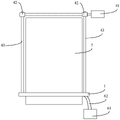
图1是本实用新型实施例提供的一种用于电除尘器的清灰装置的结构示意图;1 is a schematic structural diagram of a dust cleaning device for an electrostatic precipitator provided by an embodiment of the present invention;
图2是本实用新型实施例提供的一种集尘管的结构示意图;2 is a schematic structural diagram of a dust collecting pipe provided by an embodiment of the present invention;
图3是本实用新型实施例提供的另一种用于电除尘器的清灰装置的结构示意图;3 is a schematic structural diagram of another dust cleaning device for an electrostatic precipitator provided by an embodiment of the present invention;
图4是本实用新型实施例提供的一种清灰装置的侧视图;4 is a side view of a dust cleaning device provided by an embodiment of the present invention;
图5是本实用新型实施例提供的一种吸尘孔的分布示意图;5 is a schematic diagram of the distribution of dust suction holes provided by an embodiment of the present invention;
图6是本实用新型实施例提供的另一种吸尘孔的分布示意图。FIG. 6 is a schematic diagram of the distribution of another dust suction hole provided by an embodiment of the present invention.
图中各符号表示含义如下:The meanings of the symbols in the figure are as follows:
1-集尘管,11-吸尘孔,2-除尘刷,3-安装架,41-驱动电机,42-驱动齿轮,43-驱动齿条,44-导链,5-连通管,61-排风机,62-连接管道,7-阳极板。1- Dust collection pipe, 11- Dust hole, 2- Dust brush, 3- Mounting frame, 41- Drive motor, 42- Drive gear, 43- Drive rack, 44- Guide chain, 5- Connecting pipe, 61- Exhaust fan, 62-connecting pipe, 7-anode plate.
具体实施方式Detailed ways
为使本实用新型的目的、技术方案和优点更加清楚,下面将结合附图对本实用新型实施方式作进一步地详细描述。In order to make the objectives, technical solutions and advantages of the present utility model more clear, the embodiments of the present utility model will be further described in detail below with reference to the accompanying drawings.
图1是本实用新型实施例提供的一种用于电除尘器的清灰装置的结构示意图。如图1所示,该清灰装置包括:集尘管1、除尘刷2、真空组件和用于驱动集尘管1移动的驱动组件,集尘管1外壁上设有吸尘孔11,除尘刷2位于集尘管1的外壁,真空组件用于将集尘管1的内部空间抽至真空。FIG. 1 is a schematic structural diagram of a dust cleaning device for an electrostatic precipitator provided by an embodiment of the present invention. As shown in Figure 1, the dust cleaning device includes: a dust collecting
本实用新型实施例在集尘管的外壁上设置了除尘刷,在使用时通过控制驱动组件使得集尘管在电除尘器的阴极板或阳极板的侧面上往复移动,并通过除尘刷使阴极板或阳极板上沉积的粉尘与阴极板或阳极板剥离,从而可以全面地将吸附在阴极板或阳极板上的粉尘刷落,同时集尘管的外壁上还设有吸尘孔,且集尘管的内部空间可以通过排风机将抽空,使得集尘管内保持一定真空度,因此通过吸尘孔就可以将从阴极板或阳极板剥离的粉尘吸入集尘管内,并最终通过集尘管排出,由于通过具有真空度的集尘管可以将集尘管附近的粉尘全吸入其中,相较于现有的被动收尘方式,本实用新型收尘效果更好且更彻底,因此也能有效地避免粉尘重新返回烟气内,产生二次扬尘。In the embodiment of the present utility model, a dust-removing brush is arranged on the outer wall of the dust-collecting tube. When in use, the dust-collecting tube is reciprocated on the side of the cathode plate or the anode plate of the electrostatic precipitator by controlling the driving component, and the cathode is moved by the dust-removing brush. The dust deposited on the plate or anode plate is peeled off from the cathode plate or anode plate, so that the dust adsorbed on the cathode plate or anode plate can be completely brushed off. The inner space of the dust pipe can be evacuated by the exhaust fan, so that a certain degree of vacuum is maintained in the dust collection pipe. Therefore, the dust peeled from the cathode plate or the anode plate can be sucked into the dust collection pipe through the dust suction hole, and finally discharged through the dust collection pipe. , because the dust near the dust collection pipe can be fully inhaled through the dust collection pipe with vacuum degree, compared with the existing passive dust collection method, the dust collection effect of the utility model is better and more thorough, so it can also effectively Avoid dust returning to the flue gas, resulting in secondary dust.
图2是本实用新型实施例提供的一种集尘管1的结构示意图。如图2所述,集尘管1的数量为两个,两个集尘管1平行间隔分布,除尘刷2位于两个集尘管1之间。在本实施例中,两个集尘管1可以分别位于电除尘器的阴极板的两侧或电除尘器的阳极板7的两侧,且两个集尘管1上的除尘刷2均正对阴极板或阳极板7的侧壁。这样通过两个集尘管1同时对阴极板或阳极板7的两侧进行粉尘扫除,可以提高清灰装置的清灰效率。FIG. 2 is a schematic structural diagram of a dust collecting
如图2所示,清灰装置还可以包括安装架3,两个集尘管1的一端均与安装架3连接。本实施例中安装架3可以是连接板、连接杆等连接件,两个集尘管1的一端均固定在安装架3上,从而使两个集尘管1成为一个整体,这样在使用驱动组件驱动集尘管1沿阴极板或阳极板7的侧壁移动时,可以同时驱动两个集尘管1滑动清灰,避免为每个集尘管1都配置驱动组件,节省成本,便于使用。As shown in FIG. 2 , the dust cleaning device may further include an
在本实用新型的一些实施例中,驱动组件可以包括:驱动电机41、驱动齿轮42和驱动齿条43,驱动齿轮42套装在驱动电机41的输出轴上,驱动齿条43与驱动齿轮42啮合,集尘管1与驱动齿条43连接。如图1所示,集尘管1上设有两个驱动齿条43,两个驱动齿条43可以分别位于集尘管1的两端,且驱动电机41的输出轴上同轴设有一个传动杆,传动杆上套装有两个驱动齿轮42,其中两个驱动齿轮42分别与位于集尘管1上的两个驱动齿条43啮合。本实施例中通过设置驱动齿轮42和驱动齿条43啮合的驱动方式将驱动电机41的圆周运动转换为驱动齿条43的直线运动,在驱动齿条43的带动下,以实现集尘管1沿阴极板或阳极板7作直线运动的目的。同时,本实施例中在集尘管1的两端位置均设置了一个驱动齿条43,使得集尘管1运动时受力更加均匀,在驱动电机41的驱动下能稳定地沿阴极板或阳极板7作往复直线运动。In some embodiments of the present invention, the drive assembly may include: a
在本实用新型的另一些实施例中,如图3所示,驱动组件可以包括:驱动电机41和导链44,导链44的一端缠绕在驱动电机41的输出轴上,导链44的另一端缠绕在集尘管1上,这样在驱动电机41的驱动下可以通过导链44调整集尘管1与驱动电机41间的位置距离,从而实现集尘管1沿阴极板或阳极板7作直线运动的目的。In other embodiments of the present invention, as shown in FIG. 3 , the drive assembly may include: a
需要说明的是,除了上述驱动方式外,还可以采用其他的驱动方式,如液压油缸驱动等,本实用新型实施例在此不做限制。It should be noted that, in addition to the above-mentioned driving manners, other driving manners, such as hydraulic cylinder driving, etc., may also be adopted, which are not limited in this embodiment of the present invention.
如图2所示,清灰装置还可以包括连通管5,两个集尘管1的另一端与连通管5连通。其中连通管5可以是三通管,三通管的第一个管口与一个集尘管1的另一端连通,三通管的第二个管口与另一个集尘管1的另一端连通,三通管的第三个管口则用于与真空组件连接。本实施例通过连通管5将两个集尘管1的内部空间导通,从而在使用真空组件抽空集尘管1时,可以使用单个真空组件一次将两个集尘管1同时抽空,从而减少真空组件的设置数量,节省成本。As shown in FIG. 2 , the dust cleaning device may further include a communication pipe 5 , and the other ends of the two
本实施例中,真空组件可以包括排风机61和连接管道62,连接管道62的一端与排风机61的抽风口连通,连接管道62的另一端与集尘管1连通。如图1、2所示,连接管道62的一端与排风机61的抽风口连通,且连通管5上具有一个管口与连接管道62的另一端连通,这样通过排风机61将集尘管1内的空气抽出,从而使集尘管1的内部空间可以保持一定的真空度。In this embodiment, the vacuum assembly may include an
其中,连接管道62可以是柔性管,由于本实施例中集尘管1要在阴极板或阳极板7上作往复移动,因此集尘管1也会拉动连接管道62一起移动,而连接管道62设置成柔性管后利用其可弯折性,可以方便连接管道62跟随集尘管1一起作往复移动。The connecting
在本实用新型的其他实施例中,真空组件还可以包括真空泵和连接管道62,通过真空泵将集尘管1的内部空间抽真空。In other embodiments of the present invention, the vacuum assembly may further include a vacuum pump and a connecting
图4是本实用新型实施例提供的一种清灰装置的侧视图。如图4所示,除尘刷2的两侧均设有吸尘孔11。由于清灰装置在使用过程中会沿阴极板或阳极板7的侧壁作往复运动,因此除尘刷2在刷灰尘的过程中,除尘刷2的两侧均会存在从阴极板或阳极板7上脱离下来的粉尘,即本实用新型实施例在除尘刷2的两侧均设置吸尘孔11后,可以提高集尘管1的吸尘效果,使清灰干净彻底。4 is a side view of a dust cleaning device provided by an embodiment of the present invention. As shown in FIG. 4 , both sides of the
可选地,两个吸尘孔11的圆心分别与集尘管1的中轴线的连线的夹角α为40°至90°。设置该夹角α为40°至90°,可以保证位于除尘刷2的两侧的吸尘孔11不会因为距离过近或过远而使得吸尘孔11的吸收粉尘的效果变差。Optionally, the included angle α between the center of the two dust suction holes 11 and the line connecting the central axis of the
本实用新型的一些实施例中,吸尘孔11可以有多个,多个吸尘孔11沿集尘管1的轴向分布。如图5所示,吸尘孔11可以为圆孔,且多个圆孔沿集尘管1的轴向分布在集尘管1上。如图6所示,吸尘孔11还可以为长条孔,且多个长条孔沿集尘管1的轴向分布在集尘管1上。本实施例中,除尘刷2的刷毛也是沿集尘管1的轴向延伸布置,由于除尘刷2在刷除灰尘的过程中除尘刷2的附近会存在脱落的粉尘,因此为保证清灰效果,吸尘孔11也可以沿集尘管1的轴向分布,从而将除尘刷2附近的粉尘均通过吸尘孔11吸入集尘管1内。In some embodiments of the present invention, there may be a plurality of dust suction holes 11 , and the plurality of dust suction holes 11 are distributed along the axial direction of the
可选地,除尘刷2的刷毛为绝缘材料。绝缘材料的刷毛不导电,防止清灰装置将电流引驱动组件或真空组件内而对设备造成损坏,还可以避免刷毛上存在电荷将粉尘吸附在其上。Optionally, the bristles of the dust-removing
在使用清灰装置时,首先,将集尘管放置在电除尘器的阴极板、阳极板的侧壁上,并使集尘管的除尘刷对准阴极板、阳极板,然后控制真空组件将集尘管抽至真空,同时控制驱动组件驱动集尘管沿阴极板、阳极板作往复移动。When using the dust cleaning device, first, place the dust collecting tube on the side wall of the cathode plate and anode plate of the electrostatic precipitator, and align the dust brush of the dust collecting tube with the cathode plate and anode plate, and then control the vacuum assembly to The dust collecting pipe is evacuated to a vacuum, and at the same time, the control drive assembly drives the dust collecting pipe to reciprocate along the cathode plate and the anode plate.
本实用新型实施例提供的清灰装置,通过驱动除尘刷往复运动清灰,这样对阴极板、阳极板的清灰效果好,且集尘管内的真空对阴极板、阳极板上松散的粉尘也有吸附效果,因此在除尘刷和集尘管真空抽吸的作用下,清灰更加彻底。同时吸入集尘管内的粉尘会通过排风机排出电除尘器,因此杜绝了二次扬尘的产生。并且,由于阴极板、阳极板的大部分粉尘被清灰装置收集清理,因此减少了电除尘器的灰斗内粉尘的沉积量,且可以降低灰斗的卸灰频率,也会减少因气流不均匀而引起灰斗沉积的粉尘出现二次扬尘的量,以及卸灰过程中卸灰阀密封不好而引起的二次扬尘量。The dust cleaning device provided by the embodiment of the present invention cleans dust by driving the dust removal brush to reciprocate, so that the dust removal effect on the cathode plate and the anode plate is good, and the vacuum in the dust collecting pipe also has a good effect on the loose dust on the cathode plate and the anode plate. Therefore, under the action of the dust brush and the vacuum suction of the dust collection tube, the dust removal is more thorough. At the same time, the dust inhaled in the dust collection pipe will be discharged from the electrostatic precipitator through the exhaust fan, thus eliminating the generation of secondary dust. Moreover, since most of the dust of the cathode plate and anode plate is collected and cleaned by the ash cleaning device, the deposition amount of dust in the ash hopper of the electrostatic precipitator is reduced, and the frequency of ash unloading of the ash hopper can be reduced. The amount of secondary dust caused by the uniform dust deposited in the ash hopper, and the amount of secondary dust caused by the poor sealing of the ash discharge valve during the ash discharge process.
以上仅为本实用新型的较佳实施例,并不用以限制本实用新型,凡在本实用新型的精神和原则之内,所作的任何修改、等同替换、改进等,均应包含在本实用新型的保护范围之内。The above are only preferred embodiments of the present invention and are not intended to limit the present invention. Any modifications, equivalent replacements, improvements, etc. made within the spirit and principles of the present invention shall be included in the present invention. within the scope of protection.
Claims (10)
Priority Applications (1)
| Application Number | Priority Date | Filing Date | Title |
|---|---|---|---|
| CN201920142390.4U CN209997799U (en) | 2019-01-28 | 2019-01-28 | Ash cleaning device for electric dust collector |
Applications Claiming Priority (1)
| Application Number | Priority Date | Filing Date | Title |
|---|---|---|---|
| CN201920142390.4U CN209997799U (en) | 2019-01-28 | 2019-01-28 | Ash cleaning device for electric dust collector |
Publications (1)
| Publication Number | Publication Date |
|---|---|
| CN209997799U true CN209997799U (en) | 2020-01-31 |
Family
ID=69299884
Family Applications (1)
| Application Number | Title | Priority Date | Filing Date |
|---|---|---|---|
| CN201920142390.4U Expired - Fee Related CN209997799U (en) | 2019-01-28 | 2019-01-28 | Ash cleaning device for electric dust collector |
Country Status (1)
| Country | Link |
|---|---|
| CN (1) | CN209997799U (en) |
Cited By (1)
| Publication number | Priority date | Publication date | Assignee | Title |
|---|---|---|---|---|
| CN115212659A (en) * | 2022-09-06 | 2022-10-21 | 中科纳清(江苏)科技有限公司 | Triboelectric nano-sheet filter element |
-
2019
- 2019-01-28 CN CN201920142390.4U patent/CN209997799U/en not_active Expired - Fee Related
Cited By (1)
| Publication number | Priority date | Publication date | Assignee | Title |
|---|---|---|---|---|
| CN115212659A (en) * | 2022-09-06 | 2022-10-21 | 中科纳清(江苏)科技有限公司 | Triboelectric nano-sheet filter element |
Similar Documents
| Publication | Publication Date | Title |
|---|---|---|
| CN109173532A (en) | A kind of electric automatization cleaner | |
| CN109013439A (en) | A kind of electronic components processing surface impurity removing equipment | |
| CN209918406U (en) | Dust collector for battery pole piece | |
| CN211099566U (en) | Dry-wet composite ash removal type electric dust remover with final-stage electric field | |
| CN216779735U (en) | Air conditioner air supply system cleaning equipment | |
| CN111298971A (en) | Two-dimensional airflow high-efficiency electric dust remover | |
| CN109821658A (en) | Dust cleaning device for electrostatic precipitator | |
| CN216936493U (en) | A new type of electrostatic filter with electrode structure | |
| CN212680494U (en) | Air purification dust collector convenient to inside clearance | |
| CN109200697A (en) | A kind of automation dust-extraction unit | |
| CN218690457U (en) | New fan of electrostatic precipitator purification | |
| CN212597326U (en) | Dust removal device for double stacker | |
| CN222111237U (en) | A circuit board wave soldering device | |
| CN220779451U (en) | Environment-friendly dust treatment equipment for municipal construction | |
| CN217235997U (en) | Clean factory building energy-saving equipment in tall and big space based on EC fan uses | |
| CN217019860U (en) | A device for cleaning release agent | |
| CN113663947B (en) | Computer room host cleaning and maintaining equipment | |
| CN209424194U (en) | A kind of electrical equipment dust-extraction unit | |
| CN213349854U (en) | Dust collector is used in aerated brick production | |
| CN212250519U (en) | Fan filter assembly capable of preventing heat exchanger core from being blocked | |
| CN109124506A (en) | A kind of easy to operate scrubbing machine people | |
| CN224194346U (en) | Boiler smoke exhaust device of thermal power plant | |
| CN220678996U (en) | Novel dust collector of wire drawing machine | |
| CN223170548U (en) | Self-ash-cleaning mechanism of bag type dust collector | |
| CN214865999U (en) | Double-station switching cleaning type dust removal device for feed enzyme preparation production |
Legal Events
| Date | Code | Title | Description |
|---|---|---|---|
| GR01 | Patent grant | ||
| GR01 | Patent grant | ||
| CF01 | Termination of patent right due to non-payment of annual fee |
Granted publication date: 20200131 Termination date: 20210128 |
|
| CF01 | Termination of patent right due to non-payment of annual fee |