CN209981744U - Metal armor of multilayer function integrated configuration puts aside and closes high tension switchgear - Google Patents
Metal armor of multilayer function integrated configuration puts aside and closes high tension switchgear Download PDFInfo
- Publication number
- CN209981744U CN209981744U CN201922202502.3U CN201922202502U CN209981744U CN 209981744 U CN209981744 U CN 209981744U CN 201922202502 U CN201922202502 U CN 201922202502U CN 209981744 U CN209981744 U CN 209981744U
- Authority
- CN
- China
- Prior art keywords
- box
- diaphragm
- fixedly connected
- switch cabinet
- sides
- Prior art date
- Legal status (The legal status is an assumption and is not a legal conclusion. Google has not performed a legal analysis and makes no representation as to the accuracy of the status listed.)
- Active
Links
- 239000002184 metal Substances 0.000 title claims abstract description 23
- 239000000428 dust Substances 0.000 claims abstract description 26
- 230000000694 effects Effects 0.000 abstract description 4
- 238000000034 method Methods 0.000 description 9
- 230000017525 heat dissipation Effects 0.000 description 6
- 239000002131 composite material Substances 0.000 description 4
- 230000008569 process Effects 0.000 description 4
- 230000009471 action Effects 0.000 description 3
- 230000032683 aging Effects 0.000 description 2
- 229910000831 Steel Inorganic materials 0.000 description 1
- 230000004075 alteration Effects 0.000 description 1
- 230000009286 beneficial effect Effects 0.000 description 1
- 230000008901 benefit Effects 0.000 description 1
- 230000005540 biological transmission Effects 0.000 description 1
- 230000000903 blocking effect Effects 0.000 description 1
- 238000006243 chemical reaction Methods 0.000 description 1
- 238000009434 installation Methods 0.000 description 1
- 230000007246 mechanism Effects 0.000 description 1
- 238000005065 mining Methods 0.000 description 1
- 238000012986 modification Methods 0.000 description 1
- 230000004048 modification Effects 0.000 description 1
- 238000010248 power generation Methods 0.000 description 1
- 230000002035 prolonged effect Effects 0.000 description 1
- 238000005096 rolling process Methods 0.000 description 1
- 239000010959 steel Substances 0.000 description 1
- 238000006467 substitution reaction Methods 0.000 description 1
- 239000004753 textile Substances 0.000 description 1
Images


Landscapes
- Patch Boards (AREA)
Abstract
The utility model discloses a multilayer function integrated configuration metal armor puts aside and closes high tension switchgear, the power distribution box comprises a box body, fixedly connected with diaphragm between the both sides of box inner wall, the top fixedly connected with air exhauster of diaphragm, the suction opening intercommunication of air exhauster has the exhaust column, the one end of exhaust column runs through the diaphragm and extends to the bottom of diaphragm, the one end intercommunication that the exhaust column extends to the diaphragm bottom has the shunt tubes, the bottom on shunt tubes surface is provided with the air suction fill. A multilayer function integrated configuration metal armor put aside and close high tension switchgear, be equipped with shunt tubes and cooler, can prevent that the inside dust of cubical switchboard from causing the jam to equipment to improved the life of cubical switchboard, be fit for using widely, can also improve the user state of cubical switchboard internal plant, reduced the loss, thereby improved the work efficiency of cubical switchboard, excellent in use effect brings better use prospect.
Description
Technical Field
The utility model relates to a cubical switchboard technical field specifically is a multilayer function integrated configuration metal armor puts aside and closes high tension switchgear.
Background
The switch cabinet is an electrical device, the external line of the switch cabinet firstly enters a main control switch in the cabinet and then enters a branch control switch, and each branch is arranged according to the requirement. Such as meters, automatic controls, magnetic switches of motors, various alternating current contactors, and the like, some of which are also provided with high-voltage chambers and low-voltage chamber switch cabinets, and high-voltage buses, such as power plants, and some of which are also provided with low-frequency load shedding for keeping main equipment. The main function of the switch cabinet is to open and close, control and protect electric equipment in the process of power generation, power transmission, power distribution and electric energy conversion of an electric power system. The components in the switch cabinet mainly comprise a circuit breaker, an isolating switch, a load switch, an operating mechanism, a mutual inductor, various protection devices and the like. The classification methods of the switch cabinets are various, for example, the switch cabinets can be divided into movable switch cabinets and fixed switch cabinets by the installation mode of the circuit breaker; or according to different cabinet body structures, the cabinet body can be divided into an open type switch cabinet, a metal closed switch cabinet and a metal closed armored switch cabinet; the high-voltage switch cabinet, the medium-voltage switch cabinet, the low-voltage switch cabinet and the like can be divided according to different voltage grades. The method is mainly suitable for various occasions such as power plants, transformer substations, petrochemical industry, metallurgical steel rolling, light industrial textile, industrial and mining enterprises, residential districts, high-rise buildings and the like.
The inside of current cubical switchboard in use can not remove dust to the cubical switchboard for inside dust can lead to the jam of internal plant, has reduced the life of internal plant, and can not carry out dampproofing processing to the inside of cubical switchboard, makes the inside equipment of cubical switchboard ageing, has reduced the result of use of equipment.
Disclosure of Invention
Technical problem to be solved
The utility model provides a not enough to prior art, the utility model provides a multilayer function integrated configuration metal armor puts aside and closes high tension switchgear, possesses and prevents that the inside dust of cubical switchboard from causing the jam to equipment to improve the life of cubical switchboard, be fit for advantage such as using widely, solved the inside equipment of cubical switchboard ageing, reduced the result of use's of equipment problem.
(II) technical scheme
In order to achieve the above object, the utility model provides a following technical scheme: the utility model provides a multilayer function integrated configuration metal armor puts aside and closes high tension switchgear, the power distribution box comprises a box body, fixedly connected with diaphragm between the both sides of box inner wall, the top fixedly connected with air exhauster of diaphragm, the suction opening intercommunication of air exhauster has the exhaust column, the one end of exhaust column runs through the diaphragm and extends to the bottom of diaphragm, the one end intercommunication that the exhaust column extends to the diaphragm bottom has the shunt tubes, the bottom on shunt tubes surface is provided with the air suction fill, the top fixedly connected with dust remover of diaphragm, one side of box is provided with the gas outlet, the inside of box is provided with the part.
Preferably, the top fixedly connected with fixed block on shunt tubes surface, the top of fixed block and the bottom fixed connection of diaphragm, the quantity of fixed block is three groups.
Preferably, the air outlet of the exhaust fan is communicated with an air outlet pipe, and one end of the air outlet pipe is communicated with one side of the dust remover.
Preferably, a bottom plate is fixedly connected between two sides of the inner wall of the box body, openings are formed in two sides of the bottom plate, and the number of the openings is two.
Preferably, the bottom of the inner wall of the box body is fixedly connected with a cooler, through holes are formed in the two sides of the box body, baffles are fixedly connected to the two sides of the bottom of the inner wall of the box body, and the tops of the baffles are fixedly connected with the bottom of the bottom plate.
Preferably, the back of the box body is provided with heat dissipation holes, and screws are arranged on the back of the box body and on one side of the heat dissipation holes.
Preferably, the surface of the box body is hinged with a box door through a hinge, and the surface of the box door is fixedly connected with a buckle.
(III) advantageous effects
Compared with the prior art, the utility model provides a multilayer function integrated configuration metal armor puts aside and closes high tension switchgear, possesses following beneficial effect:
1. this multilayer function integrated configuration metal armor puts aside and closes high tension switchgear, through starting the air exhauster, with the dust through the shunt tubes that inhales wind hopper and emits into, the rethread shunt tubes emits into the exhaust column, the rethread goes out the tuber pipe and emits into the dust remover, handle the dust through the dust remover, discharge the dust through the gas outlet at last, be convenient for absorb the inside dust of cubical switchboard, prevent that the inside dust of cubical switchboard from leading to the fact equipment to block up, thereby the life of cubical switchboard has been improved, and is suitable for being generalized to use.
2. This multilayer function integrated configuration metal armor puts aside and closes high tension switchgear, fixedly connected with bottom plate between the both sides through the box inner wall, the both sides of bottom plate all are provided with the opening, open-ended quantity is two sets of, the bottom fixedly connected with cooler of box inner wall, the both sides of box all are provided with the through-hole, the equal fixedly connected with baffle in both sides of box inner wall bottom is convenient for adjust the inside temperature of cubical switchboard, prevent that moist phenomenon from appearing in the inside of cubical switchboard, the user state of cubical switchboard internal plant has been improved, the loss is reduced, thereby the work efficiency of cubical switchboard has been improved, excellent in use effect.
Drawings
Fig. 1 is a schematic structural view of a metal armored high-voltage switchgear with a multi-layer functional composite structure according to the present invention;
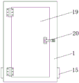
FIG. 2 is a rear view of the metal armored high-voltage switchgear cabinet of the multi-layer functional composite structure of the present invention;
fig. 3 is a front view of the metal armor of the multi-layer functional composite structure of the utility model moving away the box of the high-voltage switch cabinet.
In the figure: 1. a box body; 2. a transverse plate; 3. an exhaust fan; 4. an exhaust pipe; 5. a shunt tube; 6. a suction hopper; 7. an air outlet pipe; 8. a dust remover; 9. an air outlet; 10. a part; 11. a base plate; 12. an opening; 13. a cooler; 14. a baffle plate; 15. a through hole; 16. a fixed block; 17. heat dissipation holes; 18. a screw; 19. a box door; 20. and (5) buckling.
Detailed Description
The technical solutions in the embodiments of the present invention will be described clearly and completely with reference to the accompanying drawings in the embodiments of the present invention, and it is obvious that the described embodiments are only some embodiments of the present invention, not all embodiments. Based on the embodiments in the present invention, all other embodiments obtained by a person skilled in the art without creative work belong to the protection scope of the present invention.
Please refer to fig. 1-3, a metal armor of a multi-layer functional composite structure is moved away and is closed high voltage switch cabinet, which comprises a box body 1, a transverse plate 2 is fixedly connected between two sides of the inner wall of the box body 1, an exhaust fan 3 is fixedly connected to the top of the transverse plate 2, an exhaust opening of the exhaust fan 3 is communicated with an exhaust pipe 4, one end of the exhaust pipe 4 penetrates through the transverse plate 2 and extends to the bottom of the transverse plate 2, one end of the exhaust pipe 4 extending to the bottom of the transverse plate 2 is communicated with a shunt pipe 5, an exhaust hopper 6 is arranged at the bottom of the surface of the shunt pipe 5, the model of the exhaust fan 3 is T35-11, a dust remover 8 is fixedly connected to the top of the transverse plate 2.
Further, the top fixedly connected with fixed block 16 on shunt tubes 5 surface, the top of fixed block 16 and the bottom fixed connection of diaphragm 2, the quantity of fixed block 16 is three groups, has improved shunt tubes 5's stability.
Further, the air outlet of the exhaust fan 3 is communicated with an air outlet pipe 7, and one end of the air outlet pipe 7 is communicated with one side of the dust remover 8, so that collected dust is conveniently treated.
Further, fixedly connected with bottom plate 11 between the both sides of box 1 inner wall, the both sides of bottom plate 11 all are provided with opening 12, and the quantity of opening 12 is two sets of, is convenient for discharge the dust after handling.
Further, the bottom fixedly connected with cooler 13 of box 1 inner wall, the both sides of box 1 all are provided with through-hole 15, the equal fixedly connected with baffle 14 in both sides of box 1 inner wall bottom, and the top of baffle 14 and the bottom fixed connection of bottom plate 11 are convenient for remove damp to the inside of box 1.
Further, the back of the box body 1 is provided with heat dissipation holes 17, and one side of the back of the box body 1, which is located at the heat dissipation holes 17, is provided with screws 18, so that heat dissipation is facilitated inside the box body 1.
Furthermore, the surface of the box body 1 is hinged with a box door 19 through a hinge, and a buckle 20 is fixedly connected to the surface of the box door 19, so that the equipment inside the box body 1 can be conveniently checked and maintained.
The working principle is as follows: by starting the exhaust fan 3, dust is discharged into the shunt tubes 5 through the air suction hopper 6, then is discharged into the exhaust pipe 4 through the shunt tubes 5, then is discharged into the dust remover 8 through the air outlet pipe 7, the dust is treated through the dust remover 8, and finally is discharged through the air outlet 9, so that the dust in the switch cabinet is conveniently sucked, the dust in the switch cabinet is prevented from blocking equipment, the service life of the switch cabinet is prolonged, the switch cabinet is suitable for popularization and use, the bottom plate 11 is fixedly connected between two sides of the inner wall of the box body 1, the two sides of the bottom plate 11 are respectively provided with the openings 12, the number of the openings 12 is two groups, the bottom of the inner wall of the box body 1 is fixedly connected with the cooler 13, the two sides of the box body 1 are respectively provided with the through holes 15, the two sides of the bottom of the inner wall of the box body 1 are respectively and fixedly connected with the baffle plates 14 so, the service condition of the internal equipment of the switch cabinet is improved, and the loss is reduced, so that the working efficiency of the switch cabinet is improved, and the using effect is good.
It is noted that, herein, relational terms such as first and second, and the like may be used solely to distinguish one entity or action from another entity or action without necessarily requiring or implying any actual such relationship or order between such entities or actions. Also, the terms "comprises," "comprising," or any other variation thereof, are intended to cover a non-exclusive inclusion, such that a process, method, article, or apparatus that comprises a list of elements does not include only those elements but may include other elements not expressly listed or inherent to such process, method, article, or apparatus. Without further limitation, an element defined by the phrase "comprising an … …" does not exclude the presence of other identical elements in a process, method, article, or apparatus that comprises the element.
Although embodiments of the present invention have been shown and described, it will be appreciated by those skilled in the art that changes, modifications, substitutions and alterations can be made in these embodiments without departing from the principles and spirit of the invention, the scope of which is defined in the appended claims and their equivalents.
Claims (7)
1. The utility model provides a multilayer function integrated configuration metal armor puts aside and closes high tension switchgear, includes box (1), its characterized in that: fixedly connected with diaphragm (2) between the both sides of box (1) inner wall, top fixedly connected with air exhauster (3) of diaphragm (2), the suction opening intercommunication of air exhauster (3) has exhaust column (4), the one end of exhaust column (4) runs through diaphragm (2) and extends to the bottom of diaphragm (2), the one end intercommunication that exhaust column (4) extended to diaphragm (2) bottom has shunt tubes (5), the bottom on shunt tubes (5) surface is provided with air suction hopper (6), the top fixedly connected with dust remover (8) of diaphragm (2), one side of box (1) is provided with gas outlet (9), the inside of box (1) is provided with part (10).
2. The metal armored high-voltage switch cabinet with a multilayer functional combined structure as claimed in claim 1, wherein: the top fixedly connected with fixed block (16) on shunt tubes (5) surface, the top of fixed block (16) and the bottom fixed connection of diaphragm (2), the quantity of fixed block (16) is three groups.
3. The metal armored high-voltage switch cabinet with a multilayer functional combined structure as claimed in claim 1, wherein: the air outlet of the exhaust fan (3) is communicated with an air outlet pipe (7), and one end of the air outlet pipe (7) is communicated with one side of the dust remover (8).
4. The metal armored high-voltage switch cabinet with a multilayer functional combined structure as claimed in claim 1, wherein: fixedly connected with bottom plate (11) between the both sides of box (1) inner wall, the both sides of bottom plate (11) all are provided with opening (12), the quantity of opening (12) is two sets of.
5. The metal armored high-voltage switch cabinet with a multilayer functional combined structure as claimed in claim 1, wherein: the bottom fixedly connected with cooler (13) of box (1) inner wall, the both sides of box (1) all are provided with through-hole (15), the equal fixedly connected with baffle (14) in both sides of box (1) inner wall bottom, the top of baffle (14) and the bottom fixed connection of bottom plate (11).
6. The metal armored high-voltage switch cabinet with a multilayer functional combined structure as claimed in claim 1, wherein: the back of box (1) is provided with louvre (17), the back of box (1) and be located one side of louvre (17) and be provided with screw (18).
7. The metal armored high-voltage switch cabinet with a multilayer functional combined structure as claimed in claim 1, wherein: the surface of the box body (1) is hinged with a box door (19) through a hinge, and a buckle (20) is fixedly connected to the surface of the box door (19).
Priority Applications (1)
| Application Number | Priority Date | Filing Date | Title |
|---|---|---|---|
| CN201922202502.3U CN209981744U (en) | 2019-12-11 | 2019-12-11 | Metal armor of multilayer function integrated configuration puts aside and closes high tension switchgear |
Applications Claiming Priority (1)
| Application Number | Priority Date | Filing Date | Title |
|---|---|---|---|
| CN201922202502.3U CN209981744U (en) | 2019-12-11 | 2019-12-11 | Metal armor of multilayer function integrated configuration puts aside and closes high tension switchgear |
Publications (1)
| Publication Number | Publication Date |
|---|---|
| CN209981744U true CN209981744U (en) | 2020-01-21 |
Family
ID=69251864
Family Applications (1)
| Application Number | Title | Priority Date | Filing Date |
|---|---|---|---|
| CN201922202502.3U Active CN209981744U (en) | 2019-12-11 | 2019-12-11 | Metal armor of multilayer function integrated configuration puts aside and closes high tension switchgear |
Country Status (1)
| Country | Link |
|---|---|
| CN (1) | CN209981744U (en) |
Cited By (1)
| Publication number | Priority date | Publication date | Assignee | Title |
|---|---|---|---|---|
| CN111416292A (en) * | 2020-05-19 | 2020-07-14 | 安徽同胜电力科技有限公司 | A exhaust device that is used for switch board cooling to use adjustable angle |
-
2019
- 2019-12-11 CN CN201922202502.3U patent/CN209981744U/en active Active
Cited By (2)
| Publication number | Priority date | Publication date | Assignee | Title |
|---|---|---|---|---|
| CN111416292A (en) * | 2020-05-19 | 2020-07-14 | 安徽同胜电力科技有限公司 | A exhaust device that is used for switch board cooling to use adjustable angle |
| CN111416292B (en) * | 2020-05-19 | 2021-07-13 | 广西电控电气集团有限公司 | Angle-adjustable exhaust device for cooling power distribution cabinet |
Similar Documents
| Publication | Publication Date | Title |
|---|---|---|
| CN109586202B (en) | Internal combustion arc pressure relief collecting device for prefabricated substation | |
| CN107959248B (en) | A kind of open air dust-proof radiating high-voltage appliance switch cabinet | |
| CN204558956U (en) | A kind of high efficiency and heat radiation high-voltage ring main unit | |
| CN213584885U (en) | Low-voltage complete draw-out type switch cabinet | |
| CN210246114U (en) | Draw-out type low-voltage switch cabinet | |
| CN205039421U (en) | Heat -dissipation switch cabinet | |
| CN214124619U (en) | Drawer type switch cabinet with improved plug-in structure | |
| CN211266041U (en) | Anti-interference device of high-low voltage switch cabinet | |
| CN216362215U (en) | Energy-saving environment-friendly low-voltage switch cabinet | |
| CN213151471U (en) | Armour moving type AC metal enclosed switch equipment | |
| CN215299824U (en) | Novel mixed loading type switch cabinet | |
| CN215119649U (en) | High-voltage switch cabinet with strong heat dissipation performance | |
| CN107591690B (en) | Ventilated switch cabinet | |
| CN207518141U (en) | A kind of outdoor thunder-prevention switch cabinet | |
| CN214379633U (en) | Built-in water conservancy diversion dust removal structure's cubical switchboard | |
| CN213484330U (en) | Switch cabinet with optimized heat dissipation | |
| CN219321828U (en) | Low-voltage complete switch cabinet with dedusting and cooling functions | |
| CN207691286U (en) | A kind of intelligent AC low-voltage complete switch equipment | |
| CN210744484U (en) | Rainproof and moistureproof switch equipment | |
| CN214100281U (en) | Dampproofing waterproof type cubical switchboard | |
| CN213717328U (en) | Switch electric cabinet with dehumidification structure | |
| CN209805233U (en) | Novel low-voltage draw-out type switch cabinet | |
| CN211405027U (en) | Alarm device for closed high-voltage switch cabinet | |
| CN221080738U (en) | Box-type outdoor switching station | |
| CN215645671U (en) | An indoor metal armored withdrawable switchgear |
Legal Events
| Date | Code | Title | Description |
|---|---|---|---|
| GR01 | Patent grant | ||
| GR01 | Patent grant |