CN209969779U - A cutting device for mechanical engineering - Google Patents
A cutting device for mechanical engineering Download PDFInfo
- Publication number
- CN209969779U CN209969779U CN201920882583.3U CN201920882583U CN209969779U CN 209969779 U CN209969779 U CN 209969779U CN 201920882583 U CN201920882583 U CN 201920882583U CN 209969779 U CN209969779 U CN 209969779U
- Authority
- CN
- China
- Prior art keywords
- cutting
- platform
- motor
- mechanical engineering
- cutting device
- Prior art date
- Legal status (The legal status is an assumption and is not a legal conclusion. Google has not performed a legal analysis and makes no representation as to the accuracy of the status listed.)
- Expired - Fee Related
Links
Images

Landscapes
- Milling, Drilling, And Turning Of Wood (AREA)
Abstract
本实用新型公开一种机械工程用切割装置,包括传送组件、第一平台和第二平台,所述传送组件的前侧设有第一平台,且传送组件的后侧设有第二平台,所述第二平台顶部的后端设有台座,且台座上设有导轨,所述导轨上活动安装有导块,所述台座上的中间位置处通过轴承座安装有螺纹丝杆,且螺纹丝杆适配贯穿所述导块,一侧的所述轴承座上设有驱动所述螺纹丝杆的马达,所述导块的前端设有导座,且导座上设有电磁滑轨;本实用新型可以改变切割组件切割的左右位置,以及切割的前后位置,可以改变切割的高度,还可以改变切割片为横切或竖切,整体来说,方便对多位置、多方向进行切割,无需人力调换工件,比较方便。

The utility model discloses a cutting device for mechanical engineering, which comprises a transmission component, a first platform and a second platform. The rear end of the top of the second platform is provided with a pedestal, and the pedestal is provided with a guide rail, a guide block is movably installed on the guide rail, and a threaded screw rod is installed at the middle position of the pedestal through the bearing seat, and the threaded screw rod is installed. It is adapted to pass through the guide block, the bearing seat on one side is provided with a motor for driving the threaded screw, the front end of the guide block is provided with a guide seat, and the guide seat is provided with an electromagnetic slide rail; The new type can change the left and right positions of the cutting component, as well as the front and rear positions of the cutting, the height of the cutting, and the cutting blade can be changed to horizontal or vertical cutting. On the whole, it is convenient for multi-position and multi-direction cutting without manpower. It is more convenient to exchange workpieces.
Description
技术领域technical field
本实用新型涉及切割设备技术领域,尤其涉及一种机械工程用切割装置。The utility model relates to the technical field of cutting equipment, in particular to a cutting device for mechanical engineering.
背景技术Background technique
在机械工程和制造中,常常需要用到切割这种加工方式,可对金属、木材、塑料等各种材质进行切割作业,在机械加工领域,切割装置是必不可少的一部分,切割的质量直接决定了最终成品的质量,现有技术中,切割装置比较单一,一般只能对固定位置、固定方向进行切割,加工过程中需要人力调换工件切割位置,比较麻烦,而且还容易造成工件位置固定不准,切割偏差等情况,因此,本实用新型提出一种机械工程用切割装置以解决现有技术中存在的问题。In mechanical engineering and manufacturing, cutting is often used to perform cutting operations on various materials such as metal, wood, and plastic. In the field of mechanical processing, cutting devices are an indispensable part, and the quality of cutting is directly It determines the quality of the final product. In the prior art, the cutting device is relatively simple, and generally can only cut at a fixed position and a fixed direction. In the process of processing, it is necessary to manually change the cutting position of the workpiece, which is troublesome, and it is easy to cause the workpiece position to be fixed incorrectly. Therefore, the utility model proposes a cutting device for mechanical engineering to solve the problems existing in the prior art.
实用新型内容Utility model content
针对上述问题,本实用新型提出一种机械工程用切割装置,该机械工程用切割装置通过螺纹丝杆带动导块沿着导轨移动,方便改变切割组件切割的左右位置,通过电磁滑块沿着电磁滑轨移动方便改变切割组件切割的前后位置,通过气压缸可以改变切割的高度,通过第一电机带动转盘旋转,方便改变切割片为横切或竖切,整体来说,方便对多位置、多方向进行切割,无需人力调换工件,比较方便。In view of the above problems, the utility model proposes a cutting device for mechanical engineering. The cutting device for mechanical engineering drives a guide block to move along a guide rail through a threaded screw rod, so as to easily change the left and right positions of the cutting assembly. The sliding rail moves to facilitate changing the front and rear positions of the cutting assembly. The height of the cutting can be changed through the pneumatic cylinder, and the turntable is driven to rotate by the first motor, which is convenient to change the cutting blade to horizontal or vertical cutting. It is more convenient to cut in the same direction without manpower changing the workpiece.
为了解决上述问题,本实用新型提出一种机械工程用切割装置,包括传送组件、第一平台和第二平台,所述传送组件的前侧设有第一平台,且传送组件的后侧设有第二平台,所述第二平台顶部的后端设有台座,且台座上设有导轨,所述导轨上活动安装有导块,所述台座上的中间位置处通过轴承座安装有螺纹丝杆,且螺纹丝杆适配贯穿所述导块,一侧的所述轴承座上设有驱动所述螺纹丝杆的马达,所述导块的前端设有导座,且导座上设有电磁滑轨,所述电磁滑轨上活动安装有电磁滑块,所述电磁滑块的一侧设有气压缸,且气压缸的输出端设有切割组件,所述第一平台和第二平台顶部的内端均设有夹持组件。In order to solve the above problems, the present utility model proposes a cutting device for mechanical engineering, which includes a transmission assembly, a first platform and a second platform. The front side of the transmission assembly is provided with a first platform, and the rear side of the transmission assembly is provided The second platform, the rear end of the top of the second platform is provided with a pedestal, and the pedestal is provided with a guide rail, a guide block is movably installed on the guide rail, and a threaded screw rod is installed in the middle position of the pedestal through a bearing seat , and the threaded screw is adapted to pass through the guide block, the bearing seat on one side is provided with a motor for driving the threaded screw, the front end of the guide block is provided with a guide seat, and the guide seat is provided with an electromagnetic A slide rail, an electromagnetic slider is movably installed on the electromagnetic slide rail, a pneumatic cylinder is arranged on one side of the electromagnetic slider, and a cutting assembly is arranged at the output end of the pneumatic cylinder, and the tops of the first platform and the second platform are The inner ends are provided with clamping components.
进一步改进在于:所述切割组件包括安装板和转盘,所述安装板安装于所述气压缸的输出端,且安装板的底部通过转轴转动安装有转盘,所述安装板顶部的一侧设有第一电机,且第一电机的输出端通过皮带与所述转轴连接。A further improvement is that: the cutting assembly includes a mounting plate and a turntable, the mounting plate is mounted on the output end of the pneumatic cylinder, and the bottom of the mounting plate is rotated and installed with a turntable through a rotating shaft, and one side of the top of the mounting plate is provided with a turntable. A first motor, and the output end of the first motor is connected with the rotating shaft through a belt.
进一步改进在于:所述转盘的底部设有第二电机,且第二电机的底部设有支柱,所述支柱一侧的下端通过轴杆转动安装有切割片,所述第二电机的输出端通过皮带与所述轴杆连接。A further improvement is that: the bottom of the turntable is provided with a second motor, and the bottom of the second motor is provided with a strut, the lower end of one side of the strut is rotated and installed with a cutting blade, and the output end of the second motor passes through the shaft. A belt is connected to the shaft.
进一步改进在于:所述夹持组件包括液压缸和夹板,所述液压缸的输出端设有夹板。A further improvement is that: the clamping assembly includes a hydraulic cylinder and a clamping plate, and the output end of the hydraulic cylinder is provided with a clamping plate.
进一步改进在于:所述传送组件包括传送架和驱动辊,所述传送架内侧的两端均设有驱动辊,且驱动辊上绕设有传送带,所述传送架内侧的中间位置处等距设有支撑辊,且支撑辊上端支撑所述传送带。A further improvement is that: the conveying assembly includes a conveying frame and a driving roller, both ends of the inner side of the conveying frame are provided with driving rollers, and a conveying belt is wound around the driving roller, and the middle position of the inner side of the conveying frame is equidistantly arranged. There are support rollers, and the upper ends of the support rollers support the conveyor belt.
本实用新型的有益效果为:本实用新型通过螺纹丝杆带动导块沿着导轨移动,方便改变切割组件切割的左右位置,通过电磁滑块沿着电磁滑轨移动方便改变切割组件切割的前后位置,通过气压缸可以改变切割的高度,通过第一电机带动转盘旋转,方便改变切割片为横切或竖切,整体来说,方便对多位置、多方向进行切割,无需人力调换工件,比较方便,且切割过程中,通过两侧的液压缸推动夹板,可以有效对工件定位,避免切割偏差,保证加工效果,同时,切割完成后,松开夹持组件,通过传送组件可以将加工后的工件运输走,并传送上未加工的工件,适合流水线作业,效率高。The beneficial effects of the utility model are as follows: the utility model drives the guide block to move along the guide rail through the threaded screw rod, which is convenient to change the left and right positions of the cutting assembly cutting, and the electromagnetic slider moves along the electromagnetic sliding rail to conveniently change the front and rear positions of the cutting assembly cutting. , The cutting height can be changed by the pneumatic cylinder, and the turntable is driven by the first motor to rotate, which is convenient to change the cutting blade to horizontal or vertical cutting. On the whole, it is convenient to cut in multiple positions and directions, and it is more convenient to replace the workpiece without manpower. , and during the cutting process, the hydraulic cylinders on both sides can push the splint, which can effectively position the workpiece, avoid cutting deviation, and ensure the processing effect. Transport away and transfer unprocessed workpieces, suitable for assembly line operations, with high efficiency.
附图说明Description of drawings
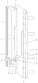
图1为本实用新型的主视图。Fig. 1 is the front view of the utility model.
图2为本实用新型的切割组件示意图。FIG. 2 is a schematic diagram of the cutting assembly of the present invention.
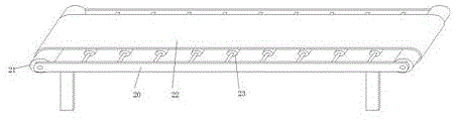
图3为本实用新型的传送组件示意图。FIG. 3 is a schematic diagram of the transmission assembly of the present invention.
其中:1、传送组件;2、第一平台;3、第二平台;4、台座;5、导轨;6、导块;7、螺纹丝杆;8、导座;9、电磁滑轨;10、电磁滑块;11、气压缸;12、安装板;13、转盘;14、第一电机;15、第二电机;16、支柱;17、切割片;18、液压缸;19、夹板;20、传送架;21、驱动辊;22、传送带;23、支撑辊。Among them: 1. Transmission assembly; 2. The first platform; 3. The second platform; 4. The pedestal; 5. The guide rail; 6. The guide block; , electromagnetic slider; 11, pneumatic cylinder; 12, mounting plate; 13, turntable; 14, first motor; 15, second motor; 16, pillar; 17, cutting piece; 18, hydraulic cylinder; 19, splint; 20 , Conveyor frame; 21, Drive roller; 22, Conveyor belt; 23, Support roller.
具体实施方式Detailed ways
为了加深对本实用新型的理解,下面将结合实施例对本实用新型做进一步详述,本实施例仅用于解释本实用新型,并不构成对本实用新型保护范围的限定。In order to deepen the understanding of the present utility model, the present utility model will be described in further detail below with reference to the embodiments. The present embodiment is only used to explain the present utility model and does not constitute a limitation on the protection scope of the present utility model.
根据图1、2、3所示,本实施例提供了一种机械工程用切割装置,包括传送组件1、第一平台2和第二平台3,所述传送组件1的前侧设有第一平台2,且传送组件1的后侧设有第二平台3,所述第二平台3顶部的后端设有台座4,且台座4上设有导轨5,所述导轨5上活动安装有导块6,所述台座4上的中间位置处通过轴承座安装有螺纹丝杆7,且螺纹丝杆7适配贯穿所述导块6,一侧的所述轴承座上设有驱动所述螺纹丝杆7的马达,马达驱动螺纹丝杆7旋转带动导块6沿着导轨5移动,方便改变切割组件切割的左右位置,所述导块6的前端设有导座8,且导座8上设有电磁滑轨9,所述电磁滑轨9上活动安装有电磁滑块10,电磁滑块10沿着电磁滑轨9移动方便改变切割组件切割的前后位置,所述电磁滑块10的一侧设有气压缸11,可以改变切割的高度,且气压缸11的输出端设有切割组件,所述第一平台2和第二平台3顶部的内端均设有夹持组件。As shown in FIGS. 1 , 2 and 3 , the present embodiment provides a cutting device for mechanical engineering, including a conveying assembly 1 , a first platform 2 and a second platform 3 , and the front side of the conveying assembly 1 is provided with a first Platform 2, and the rear side of the conveying assembly 1 is provided with a second platform 3, the rear end of the top of the second platform 3 is provided with a pedestal 4, and the pedestal 4 is provided with a guide rail 5 on which a guide rail 5 is movably installed. Block 6, a threaded
所述切割组件包括安装板12和转盘13,所述安装板12安装于所述气压缸11的输出端,且安装板12的底部通过转轴转动安装有转盘13,所述安装板12顶部的一侧设有第一电机14,第一电机14的型号为PDH160312,且第一电机14的输出端通过皮带与所述转轴连接,第一电机14通过皮带带动转盘13旋转,方便改变横切或竖切。The cutting assembly includes an
所述转盘13的底部设有第二电机15,第二电机15的型号为Y90S-2,且第二电机15的底部设有支柱16,所述支柱16一侧的下端通过轴杆转动安装有切割片17,所述第二电机15的输出端通过皮带与所述轴杆连接,第二电机15通过皮带带动切割片17旋转来切割工件。The bottom of the
所述夹持组件包括液压缸18和夹板19,所述液压缸18的输出端设有夹板19,液压缸18推动夹板19,可以有效对工件定位,避免切割偏差。The clamping assembly includes a hydraulic cylinder 18 and a clamping plate 19. The output end of the hydraulic cylinder 18 is provided with a clamping plate 19. The hydraulic cylinder 18 pushes the clamping plate 19, which can effectively position the workpiece and avoid cutting deviation.
所述传送组件1包括传送架20和驱动辊21,所述传送架20内侧的两端均设有驱动辊21,且驱动辊21上绕设有传送带22,所述传送架20内侧的中间位置处等距设有支撑辊23,且支撑辊23上端支撑所述传送带22,便于支撑传送带22的端面,方便承载工件进行切割。The conveying assembly 1 includes a conveying frame 20 and a driving roller 21 . Both ends of the inner side of the conveying frame 20 are provided with driving rollers 21 , and a conveying belt 22 is wound around the driving rollers 21 . The middle position of the inner side of the conveying frame 20 There are supporting rollers 23 equidistant from each other, and the upper end of the supporting rollers 23 supports the conveyor belt 22, which is convenient for supporting the end face of the conveyor belt 22, and is convenient for carrying the workpiece for cutting.
该机械工程用切割装置通过螺纹丝杆7带动导块6沿着导轨5移动,方便改变切割组件切割的左右位置,通过电磁滑块10沿着电磁滑轨9移动方便改变切割组件切割的前后位置,通过气压缸11可以改变切割的高度,通过第一电机14带动转盘13旋转,方便改变切割片17为横切或竖切,整体来说,方便对多位置、多方向进行切割,无需人力调换工件,比较方便,且切割过程中,通过两侧的液压缸18推动夹板19,可以有效对工件定位,避免切割偏差,保证加工效果,同时,切割完成后,松开夹持组件,通过传送组件1可以将加工后的工件运输走,并传送上未加工的工件,适合流水线作业,效率高。The mechanical engineering cutting device drives the guide block 6 to move along the guide rail 5 through the threaded
以上显示和描述了本实用新型的基本原理、主要特征和优点。本行业的技术人员应该了解,本实用新型不受上述实施例的限制,上述实施例和说明书中描述的只是说明本实用新型的原理,在不脱离本实用新型精神和范围的前提下,本实用新型还会有各种变化和改进,这些变化和改进都落入要求保护的本实用新型范围内。本实用新型要求保护范围由所附的权利要求书及其等效物界定。The basic principles, main features and advantages of the present invention have been shown and described above. It should be understood by those skilled in the art that the present invention is not limited by the above-mentioned embodiments. The above-mentioned embodiments and descriptions only illustrate the principle of the present invention. Without departing from the spirit and scope of the present invention, the present invention There will also be various changes and improvements in the new model, which all fall within the scope of the claimed invention. The claimed scope of the present invention is defined by the appended claims and their equivalents.
Claims (5)
Priority Applications (1)
| Application Number | Priority Date | Filing Date | Title |
|---|---|---|---|
| CN201920882583.3U CN209969779U (en) | 2019-06-13 | 2019-06-13 | A cutting device for mechanical engineering |
Applications Claiming Priority (1)
| Application Number | Priority Date | Filing Date | Title |
|---|---|---|---|
| CN201920882583.3U CN209969779U (en) | 2019-06-13 | 2019-06-13 | A cutting device for mechanical engineering |
Publications (1)
| Publication Number | Publication Date |
|---|---|
| CN209969779U true CN209969779U (en) | 2020-01-21 |
Family
ID=69266016
Family Applications (1)
| Application Number | Title | Priority Date | Filing Date |
|---|---|---|---|
| CN201920882583.3U Expired - Fee Related CN209969779U (en) | 2019-06-13 | 2019-06-13 | A cutting device for mechanical engineering |
Country Status (1)
| Country | Link |
|---|---|
| CN (1) | CN209969779U (en) |
Cited By (3)
| Publication number | Priority date | Publication date | Assignee | Title |
|---|---|---|---|---|
| CN112476658A (en) * | 2020-11-25 | 2021-03-12 | 德清天木坊装饰材料有限公司 | Novel improve ornamental material of structure and cut with high accuracy device |
| CN112759344A (en) * | 2021-01-04 | 2021-05-07 | 安徽省润乾节能建材科技股份有限公司 | Autoclaved sand-lime brick taking waste residues and waste materials as raw materials, production process and device |
| CN113385729A (en) * | 2021-06-10 | 2021-09-14 | 安徽国钦智能科技有限公司 | Environmental protection sanitary pipe fitting cutting device |
-
2019
- 2019-06-13 CN CN201920882583.3U patent/CN209969779U/en not_active Expired - Fee Related
Cited By (3)
| Publication number | Priority date | Publication date | Assignee | Title |
|---|---|---|---|---|
| CN112476658A (en) * | 2020-11-25 | 2021-03-12 | 德清天木坊装饰材料有限公司 | Novel improve ornamental material of structure and cut with high accuracy device |
| CN112759344A (en) * | 2021-01-04 | 2021-05-07 | 安徽省润乾节能建材科技股份有限公司 | Autoclaved sand-lime brick taking waste residues and waste materials as raw materials, production process and device |
| CN113385729A (en) * | 2021-06-10 | 2021-09-14 | 安徽国钦智能科技有限公司 | Environmental protection sanitary pipe fitting cutting device |
Similar Documents
| Publication | Publication Date | Title |
|---|---|---|
| CN109051742B (en) | Automatic feeding machine for production and processing of galvanized steel sheets | |
| CN111069695B (en) | Double-corner sawing machine | |
| CN110370145A (en) | A kind of high speed glass double side edge grinder of the full-automatic membrane removal mechanism of band | |
| CN111515446A (en) | Cutting machine with low residual loss of tailings | |
| CN209158937U (en) | A kind of laminator | |
| CN212374338U (en) | 180-degree turnover conveying equipment for heavy workpieces | |
| CN205033688U (en) | With manipulator complex arc laminating equipment | |
| CN209565569U (en) | Pipe end automatic moulding machine | |
| CN222858149U (en) | Automatic plate double-side grooving machine | |
| CN108582539A (en) | A kind of numerical control monocrystalline silicon side of cuing open machine | |
| CN210010834U (en) | Automatic wire drawing machine for stainless steel parts | |
| CN109434537B (en) | Shell machining line capable of automatically feeding and discharging | |
| CN116871577A (en) | Plate shearing machine machining finished product device that gathers materials | |
| CN216780518U (en) | Conveyer belt type multi-saw-blade cutting equipment | |
| CN211490842U (en) | Glass chamfering machine and glass conveying device thereof | |
| CN222343891U (en) | Feeding device of slotting machine | |
| CN118926948B (en) | A stamping forming equipment for battery box production | |
| CN210147132U (en) | Section bar loading attachment and saw cut equipment | |
| CN219925331U (en) | CNC full-automatic feeding and discharging equipment | |
| CN115041998A (en) | Machine tool machining is with pay-off conduction control system placed in middle | |
| CN209058211U (en) | Automatically adjust footwear printing equipment | |
| CN219130930U (en) | A processing mechanism for aluminum profiles that is convenient for discharging | |
| CN215881246U (en) | Surface machining device for aluminum production | |
| CN112278804A (en) | Automatic workpiece conveying device who leads | |
| CN223658995U (en) | Automatic feeder |
Legal Events
| Date | Code | Title | Description |
|---|---|---|---|
| GR01 | Patent grant | ||
| GR01 | Patent grant | ||
| CF01 | Termination of patent right due to non-payment of annual fee |
Granted publication date: 20200121 Termination date: 20200613 |
|
| CF01 | Termination of patent right due to non-payment of annual fee |