CN209963654U - Threading construction device for building electrical engineering - Google Patents
Threading construction device for building electrical engineering Download PDFInfo
- Publication number
- CN209963654U CN209963654U CN201921225303.8U CN201921225303U CN209963654U CN 209963654 U CN209963654 U CN 209963654U CN 201921225303 U CN201921225303 U CN 201921225303U CN 209963654 U CN209963654 U CN 209963654U
- Authority
- CN
- China
- Prior art keywords
- wire
- reel
- electrical engineering
- building electrical
- construction device
- Prior art date
- Legal status (The legal status is an assumption and is not a legal conclusion. Google has not performed a legal analysis and makes no representation as to the accuracy of the status listed.)
- Expired - Fee Related
Links
Images


Landscapes
- Electric Cable Installation (AREA)
Abstract
本实用新型涉及建筑电气施工技术领域,公开了一种建筑电气工程穿线施工装置,包括安装座、设置在安装座一端的入线模块、以及卷线模块;卷线模块包括活动座,水平转动安装在活动座上的卷轮,以及设置在活动座上用于带动卷轮转动的电机;入线模块包括压辊组件和线管,线管的一端朝向压辊组件、另一端朝向卷轮设置,压辊组件包括两个上下并列、水平转动设置的压辊,钢丝带线的固定端从两根压辊之间穿入、沿线管轴心穿过线管后固定在卷轮上。本实用新型通过电机驱动卷轮转动,钢丝带线的固定端固定在卷轮上,能够自动将钢丝带线收回缠绕到卷轮上,不需要人工手动拉回钢丝带线,拉线效率高,有效地提升了穿线的施工效率。

The utility model relates to the technical field of building electrical construction, and discloses a wire-threading construction device for building electrical engineering, comprising a mounting seat, a wire entry module arranged at one end of the mounting seat, and a wire winding module; A reel on the movable seat, and a motor arranged on the movable seat for driving the reel to rotate; the wire entry module includes a pressure roller assembly and a wire tube, one end of the wire tube is facing the pressing roller assembly, and the other end is facing the reel, The pressing roller assembly includes two pressing rollers arranged in parallel and horizontally rotating, and the fixed end of the steel strip line penetrates between the two pressing rollers, passes through the wire tube along the axis of the wire tube, and is fixed on the reel. The utility model drives the reel to rotate through the motor, the fixed end of the steel strip wire is fixed on the reel, and the steel strip wire can be automatically retracted and wound on the reel without manual pulling back of the steel strip wire, and the wire drawing efficiency is high and effective. It greatly improves the construction efficiency of threading.
Description
技术领域technical field
本实用新型涉及建筑电气施工技术领域,特别是涉及一种建筑电气工程穿线施工装置。The utility model relates to the technical field of building electrical construction, in particular to a wire-threading construction device for building electrical engineering.
背景技术Background technique
建筑电气线路都是预埋线管后,在线管内预先放入用于后期将电缆引导入线管的钢丝带线,然后再将钢丝带线从管路一端穿入管路内部,推动钢丝带线,使钢丝带线在管路中移动,直至钢丝带线从管路另一端穿出,然后将穿出的钢丝带线一端与电线进行固定连接,然后从原穿入端将钢丝带线拉回,将电线拉入到管道中,实现穿线施工。After the electrical lines of the building are all pre-buried wire pipes, the steel wire strips used to guide the cables into the wire pipes in the later stage are pre-placed in the wire pipes, and then the steel wire strips are inserted into the pipelines from one end of the pipeline to push the steel wire strips. Move the steel wire ribbon in the pipeline until the steel ribbon is pierced from the other end of the pipeline, then fix one end of the pierced steel ribbon with the wire, and then pull the steel ribbon back from the original penetration end, The wire is pulled into the pipe to realize the threading construction.
现有技术中大多数是采用人工手动将钢丝带线拉回,人工手动拉回钢丝带线虽然达到了作业的要求,但是人工拉回钢丝带线效率较慢,人工长时间拉动钢丝带线会导致工人双手酸麻,从而更加降低穿线的速度;同时当穿线过长或遇到障碍物时,人工拉线阻力较大,需要多人配合进行拉线,增加了人员的使用,降低了电气工程施工时的穿线效率,并且人工收集的带线很难有序收集,并再次利用,造成浪费。In the prior art, most of the steel belt lines are manually pulled back manually. Although the manual pull back of the steel belt lines can meet the requirements of the operation, the efficiency of manually pulling back the steel belt lines is relatively slow, and the manual pulling of the steel belt lines for a long time will cause problems. This leads to numbness in the hands of the workers, which further reduces the speed of threading; at the same time, when the threading is too long or encounters obstacles, the resistance of manual threading is large, and multiple people are required to cooperate to pull the thread, which increases the use of personnel and reduces the time required for electrical engineering construction. The threading efficiency is high, and it is difficult to collect the manually collected tapes in an orderly manner and reuse them, resulting in waste.
实用新型内容Utility model content
本实用新型提供一种拉线效率高、操作便捷、回收带线可重复利用的一种建筑电气工程穿线施工装置。The utility model provides a wire-threading construction device for a building electrical engineering, which has high wire-pulling efficiency, convenient operation, and can be recycled and reused.
解决的技术问题是:人工手动拉回钢丝带线效率较慢,影响建筑电气线路穿线施工效率。The technical problem to be solved is that the efficiency of manually pulling back the steel wire belt line is slow, which affects the construction efficiency of building electrical lines.
为解决上述技术问题,本实用新型采用如下技术方案:In order to solve the above-mentioned technical problems, the utility model adopts the following technical solutions:
本实用新型一种建筑电气工程穿线施工装置,包括安装座、设置在安装座一端用于将钢丝带线捋直的入线模块、以及设置在安装座另一端的用于缠绕钢丝带线的卷线模块;The utility model relates to a wire-threading construction device for building electrical engineering, comprising a mounting seat, a wire entry module arranged at one end of the mounting seat for straightening the steel wire ribbon, and a coil arranged at the other end of the mounting seat for winding the steel ribbon wire line module;
所述卷线模块包括活动座,水平转动安装在活动座上的卷轮,以及设置在活动座上用于带动卷轮转动的电机,所述活动座能够沿卷轮轴向往复运动;The reeling module includes a movable seat, a reel mounted on the movable seat for horizontal rotation, and a motor arranged on the movable seat for driving the reel to rotate, and the movable seat can reciprocate along the axial direction of the reel;
所述入线模块包括压辊组件和水平设置在压辊组件与卷轮之间的线管,所述线管的一端朝向压辊组件、另一端朝向卷轮设置,所述压辊组件包括两个上下并列、水平转动设置的压辊,所述钢丝带线的固定端从两根压辊之间穿入、沿线管轴向穿过线管后固定在卷轮上。The wire entry module includes a pressing roller assembly and a wire tube horizontally arranged between the pressing roller assembly and the reel. One end of the wire tube is facing the pressing roller assembly and the other end is facing the reel. The pressing roller assembly includes two There are two pressure rollers arranged in parallel and horizontally rotating, and the fixed end of the steel strip wire penetrates between the two pressure rollers, passes through the wire tube along the axial direction of the wire tube, and is fixed on the reel.
进一步,两根所述压辊的两端分别与两侧的第一支撑板转动连接,所述第一支撑板竖直设置在安装座上,底端与安装座上表面固定连接。Further, both ends of the two pressing rollers are respectively connected in rotation with the first support plates on both sides, the first support plates are vertically arranged on the mounting seat, and the bottom ends are fixedly connected with the upper surface of the mounting seat.
进一步,所述线管的底部设置有支撑块,所述支撑块固定在安装座上。Further, the bottom of the line pipe is provided with a support block, and the support block is fixed on the mounting seat.
进一步,所述线管靠近卷轮的一端上同心设置有大口径端朝向卷轮的呐叭口。Further, a bell mouth with a large diameter end facing the reel is concentrically arranged on one end of the line pipe close to the reel.
进一步,所述活动座包括底座、滑动设置在底座上的活动板、以及用于连接底座和活动板的丝杆,所述丝杆转动安装在底座内,所述活动板通过底部的滑台滑动安装在丝杆上,所述丝杆的一端从底座的侧壁穿出并在穿出的一端上设置有摇把,所述卷轮、电机均设置在活动板上,所述丝杆平行于卷轮的轴向设置,所述安装座上于底座对应位置开设有安装槽,所述底座设置在安装槽内。Further, the movable seat includes a base, a movable plate slidably arranged on the base, and a screw rod for connecting the base and the movable plate, the screw rod is rotatably installed in the base, and the movable plate slides through the sliding table at the bottom Installed on a screw rod, one end of the screw rod protrudes from the side wall of the base and a crank handle is provided on the end of the screw rod, the reel and the motor are all arranged on the movable plate, and the screw rod is parallel to the For the axial arrangement of the reel, the mounting seat is provided with a mounting groove at the corresponding position of the base, and the base is arranged in the mounting groove.
进一步,所述卷轮通过第二转轴转动安装在两块第二支撑板之间,所述第二支撑板的底部固定设置在活动板上。Further, the reel is rotatably installed between two second support plates through a second rotating shaft, and the bottom of the second support plates is fixedly arranged on the movable plate.
进一步,所述电机通过齿轮组带动卷轮转动,所述齿轮组包括固定安装在电机转轴上的主动齿轮和固定在第二转轴穿出第二支撑板的一端上、并与主动齿轮相啮合的从动齿轮。Further, the motor drives the reel to rotate through a gear set, and the gear set includes a driving gear fixed on the rotating shaft of the motor and a driving gear fixed on one end of the second rotating shaft passing through the second support plate and meshing with the driving gear. driven gear.
进一步,所述底座的顶部设置有平行于丝杆轴向的导轨,所述活动板底部于导轨对应位置设置有与导轨相配合的滑块,所述滑块滑动安装在导轨上。Further, the top of the base is provided with a guide rail parallel to the axial direction of the screw rod, and the bottom of the movable plate is provided with a sliding block matched with the guide rail at a corresponding position of the guide rail, and the sliding block is slidably installed on the guide rail.
进一步,所述安装座的底部设置有带自锁功能的万向轮。Further, the bottom of the mounting seat is provided with a universal wheel with a self-locking function.
进一步,所述安装座靠近卷轮一端的侧壁上设置有手推杆。Further, a hand push rod is provided on the side wall of the mounting seat close to one end of the reel.
本实用新型一种建筑电气工程穿线施工装置与现有技术相比,具有如下有益效果:Compared with the prior art, the utility model has the following beneficial effects:
本实用新型通过电机驱动卷轮转动,钢丝带线的固定端固定在卷轮上,能够自动将钢丝带线收回缠绕到卷轮上,不需要人工手动拉回钢丝带线,拉线效率高,有效地提升了穿线的施工效率;入线模块通过两个压辊和线管配合,将钢丝带线捋直以后再缠绕在卷轮上,避免钢丝带线在绕在卷轮上时打结;在电机带动卷轮转动从而将钢丝带线拉回时,人工手动正向和反向摇动摇把,带动丝杆转动,从而带动活动板上的卷轮沿轴向往复移动,使钢丝带线能够均匀的缠绕在卷轮上,方便下次将钢丝带线放出,便于带线的重复使用。The utility model drives the reel to rotate by the motor, the fixed end of the steel strip wire is fixed on the reel, and the steel strip wire can be automatically retracted and wound on the reel without manual pulling back of the steel strip wire, and the drawing efficiency is high and effective. The construction efficiency of threading is greatly improved; the wire entry module cooperates with the two pressing rollers and the wire tube to straighten the steel tape line and then wind it on the reel to avoid knotting when the steel tape line is wound on the reel; When the motor drives the reel to rotate and pulls the steel ribbon back, manually manually shake the handle in forward and reverse directions to drive the screw to rotate, thereby driving the reel on the movable plate to reciprocate in the axial direction, so that the steel ribbon can be evenly moved. It is wound on the reel, which is convenient for releasing the steel tape line next time, which is convenient for the repeated use of the tape line.
下面结合附图对本实用新型的一种建筑电气工程穿线施工装置作进一步说明。Below in conjunction with the accompanying drawings, a construction device for threading construction of electrical engineering in buildings of the present invention will be further described.
附图说明Description of drawings
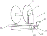
图1是本实用新型一种建筑电气工程穿线施工装置的结构示意图一;Fig. 1 is the structural representation one of a kind of construction electrical engineering threading construction device of the present utility model;
图2是本实用新型一种建筑电气工程穿线施工装置的结构示意图二;Fig. 2 is the structural representation two of a kind of construction electrical engineering threading construction device of the present utility model;
图3是本实用新型一种建筑电气工程穿线施工装置的侧视图;Fig. 3 is the side view of a kind of construction electrical engineering threading construction device of the present invention;
图4是本实用新型一种建筑电气工程穿线施工装置的卷线模块的结构示意图;4 is a schematic structural diagram of a wire winding module of a building electrical engineering wire threading construction device of the present invention;
其中,安装座1、钢丝带线2、入线模块3、活动座4、卷轮5、电机6、压辊7、第一支撑板8、支撑块9、呐叭口10、底座11、活动板12、丝杆13、摇把14、第二支撑板15、从动齿轮16、导轨17、万向轮18、手推杆19、卷线模块20、线管21。Among them, the
具体实施方式Detailed ways
如图1-图4所示,本实用新型本实用新型一种建筑电气工程穿线施工装置,包括安装座1、设置在安装座1一端用于将钢丝带线2捋直的入线模块3、以及设置在安装座1另一端的用于缠绕钢丝带线2的卷线模块20;卷线模块20包括活动座4,水平转动安装在活动座4上的卷轮5,以及设置在活动座4上用于带动卷轮5转动的电机6,活动座4能够沿卷轮5轴向往复运动以使钢丝带线2均匀缠绕在卷轮5上;入线模块3包括压辊组件和水平设置在压辊组件与卷轮5之间的线管21,线管21的一端朝向压辊组件、另一端朝向卷轮5设置,压辊组件包括两个上下并列、水平转动设置的压辊7,两根压辊7的两端分别与两侧的第一支撑板8转动连接,压辊7通过第一转轴转动安装在两块第一支撑板8之间,第一支撑板8竖直设置在安装座1上,底端与安装座1上表面固定连接,钢丝带线2的固定端从两根压辊7之间穿入、沿线管21轴向穿过线管21后固定在卷轮5上。As shown in Fig. 1-Fig. 4, the utility model is a construction device for threading construction of electrical engineering, comprising a
具体的,线管21的底部设置有支撑块9,支撑块9固定在安装座1上。线管21靠近卷轮5的一端上同心设置有大口径端朝向卷轮5的呐叭口10。当活动座4沿卷轮5轴向往复运动时,钢丝带线2会与线管21轴向发生偏移,呐叭口10用于减少钢丝带线2与线管21端部的摩擦,减少钢丝带线2的损坏。Specifically, a
活动座4包括底座11、滑动设置在底座11上的活动板12、以及用于连接底座11和活动板12的丝杆13,丝杆13转动安装在底座11内,活动板12通过底部的滑台滑动安装在丝杆13上,丝杆13的一端从底座11的侧壁穿出并在穿出的一端上设置有摇把14,卷轮5、电机6均设置在活动板12上,丝杆13平行于卷轮5的轴向设置,安装座1上于底座11对应位置开设有安装槽,底座11设置在安装槽内。卷轮5的两端均设置有第二支撑板15,卷轮5通过第二转轴转动安装在第二支撑板15上,第二支撑板15的底部固定设置在活动板12上。在电机6带动卷轮5转动从而将钢丝带线2拉回时,人工手动正向和反向摇动摇把14,带动丝杆13转动,从而带动活动板12上的卷轮5沿轴向往复移动,使钢丝带线2能够均匀的缠绕在卷轮5上,方便下次将钢丝带线2放出。The
电机6通过齿轮组带动卷轮5转动,齿轮组包括固定安装在电机6转轴上的主动齿轮和固定在第二转轴穿出第二支撑板15的一端上、并与主动齿轮相啮合的从动齿轮16。The
底座11的顶部设置有平行于丝杆13轴向的导轨17,活动板12底部于导轨17对应位置设置有与导轨17相配合的滑块,滑块滑动安装在导轨17上。导轨17和滑块配合,使活动板12运行更加平稳。The top of the base 11 is provided with a
安装座1的底部设置有带自锁功能的万向轮18。安装座1靠近卷轮5一端的侧壁上设置有手推杆19。万向轮18和手推杆19方便推动本装置到不同的地方进行施工。The bottom of the
本实用新型通过电机驱动卷轮5转动,钢丝带线2的固定端固定在卷轮5上,能够自动将钢丝带线2收回缠绕到卷轮5上,不需要人工手动拉回钢丝带线,拉线效率高,有效地提升了穿线的施工效率;入线模块3通过两个压辊7和线管21配合,将钢丝带线2捋直以后再缠绕在卷轮5上,避免钢丝带线2在绕在卷轮5上时打结;在电机6带动卷轮5转动从而将钢丝带线2拉回时,人工手动正向和反向摇动摇把14,带动丝杆13转动,从而带动活动板12上的卷轮5沿轴向往复移动,使钢丝带线2能够均匀的缠绕在卷轮5上,方便下次将钢丝带线2放出。The utility model drives the
以上所述的实施例仅仅是对本实用新型的优选实施方式进行描述,并非对本实用新型的范围进行限定,在不脱离本实用新型设计精神的前提下,本领域普通技术人员对本实用新型的技术方案作出的各种变形和改进,均应落入本实用新型权利要求书确定的保护范围内。The above-mentioned embodiments are only to describe the preferred embodiments of the present invention, and do not limit the scope of the present invention. On the premise of not departing from the design spirit of the present invention, those of ordinary skill in the art can understand the technical solutions of the present invention. Various modifications and improvements made shall fall within the protection scope determined by the claims of the present utility model.
Claims (10)
Priority Applications (1)
| Application Number | Priority Date | Filing Date | Title |
|---|---|---|---|
| CN201921225303.8U CN209963654U (en) | 2019-07-31 | 2019-07-31 | Threading construction device for building electrical engineering |
Applications Claiming Priority (1)
| Application Number | Priority Date | Filing Date | Title |
|---|---|---|---|
| CN201921225303.8U CN209963654U (en) | 2019-07-31 | 2019-07-31 | Threading construction device for building electrical engineering |
Publications (1)
| Publication Number | Publication Date |
|---|---|
| CN209963654U true CN209963654U (en) | 2020-01-17 |
Family
ID=69249148
Family Applications (1)
| Application Number | Title | Priority Date | Filing Date |
|---|---|---|---|
| CN201921225303.8U Expired - Fee Related CN209963654U (en) | 2019-07-31 | 2019-07-31 | Threading construction device for building electrical engineering |
Country Status (1)
| Country | Link |
|---|---|
| CN (1) | CN209963654U (en) |
Cited By (3)
| Publication number | Priority date | Publication date | Assignee | Title |
|---|---|---|---|---|
| CN112886487A (en) * | 2021-04-12 | 2021-06-01 | 梁金刚 | Power line threading machine |
| CN113097930A (en) * | 2021-04-08 | 2021-07-09 | 汉维科技发展有限公司 | Cable pipe-penetrating auxiliary tool in multifunctional comprehensive wiring system and use method thereof |
| CN113572083A (en) * | 2021-09-06 | 2021-10-29 | 江苏电子信息职业学院 | Threading construction device for building electrical engineering |
-
2019
- 2019-07-31 CN CN201921225303.8U patent/CN209963654U/en not_active Expired - Fee Related
Cited By (3)
| Publication number | Priority date | Publication date | Assignee | Title |
|---|---|---|---|---|
| CN113097930A (en) * | 2021-04-08 | 2021-07-09 | 汉维科技发展有限公司 | Cable pipe-penetrating auxiliary tool in multifunctional comprehensive wiring system and use method thereof |
| CN112886487A (en) * | 2021-04-12 | 2021-06-01 | 梁金刚 | Power line threading machine |
| CN113572083A (en) * | 2021-09-06 | 2021-10-29 | 江苏电子信息职业学院 | Threading construction device for building electrical engineering |
Similar Documents
| Publication | Publication Date | Title |
|---|---|---|
| CN214422022U (en) | Communication cable winding and unwinding device applied to 5G communication | |
| CN209701983U (en) | Communication cable winding device | |
| CN113044680A (en) | Cable winding and unwinding devices who uses manpower sparingly | |
| CN113998529A (en) | Automatic coiling device of isometric steel wire plastic-coated machine | |
| CN105835072A (en) | Optical fiber winding and unwinding unit for mobile robot | |
| CN219341242U (en) | Cable winding disc | |
| CN219086679U (en) | A cable pulling and laying device | |
| CN216426385U (en) | a winding device | |
| CN216638485U (en) | Antiwind coiling mechanism of wire and cable production | |
| CN220245134U (en) | A kind of trademark tape rewinding equipment | |
| CN219669772U (en) | Electromagnetic wire take-up equipment | |
| CN209777887U (en) | Cable reel combination and assembly type synchronous wire start prevention braking device | |
| CN217676039U (en) | Wire and cable coiling machine | |
| CN216105397U (en) | Cable winding and unwinding devices that electromechanical engineering facilitates use | |
| CN219541566U (en) | Galvanized wire cutter | |
| CN219697116U (en) | An automatic cable threader for electrical installations | |
| CN111463717A (en) | Subway cable laying device | |
| CN110844669A (en) | Strip coiling tension applying equipment used in slitting production line | |
| CN211393318U (en) | Cable pay-off with adjustable be qualified for next round of competitions | |
| CN115465732A (en) | Traditional chinese painting assists coiling mechanism | |
| CN205709185U (en) | The conducting mechanism of a kind of cable paying-off device and cable paying-off device | |
| CN219937792U (en) | A kind of transmission line laying equipment used in transmission line construction | |
| CN219238903U (en) | A special auxiliary device for geophysical exploration | |
| CN222312327U (en) | A wire collection device for computer network engineering | |
| CN221216663U (en) | Dust collection pipe winding device with wire arrangement function |
Legal Events
| Date | Code | Title | Description |
|---|---|---|---|
| GR01 | Patent grant | ||
| GR01 | Patent grant | ||
| CF01 | Termination of patent right due to non-payment of annual fee | ||
| CF01 | Termination of patent right due to non-payment of annual fee |
Granted publication date: 20200117 |