CN209959348U - Novel self-heat-dissipation generator - Google Patents
Novel self-heat-dissipation generator Download PDFInfo
- Publication number
- CN209959348U CN209959348U CN201820532854.8U CN201820532854U CN209959348U CN 209959348 U CN209959348 U CN 209959348U CN 201820532854 U CN201820532854 U CN 201820532854U CN 209959348 U CN209959348 U CN 209959348U
- Authority
- CN
- China
- Prior art keywords
- support frame
- generator
- lid
- cover body
- sides
- Prior art date
- Legal status (The legal status is an assumption and is not a legal conclusion. Google has not performed a legal analysis and makes no representation as to the accuracy of the status listed.)
- Expired - Fee Related
Links
- 238000009423 ventilation Methods 0.000 claims abstract description 20
- 230000017525 heat dissipation Effects 0.000 claims abstract description 5
- 239000002184 metal Substances 0.000 claims description 7
- 230000005611 electricity Effects 0.000 claims description 4
- 238000009434 installation Methods 0.000 abstract description 2
- 239000000428 dust Substances 0.000 description 3
- 238000000034 method Methods 0.000 description 3
- 239000011888 foil Substances 0.000 description 2
- 230000009286 beneficial effect Effects 0.000 description 1
- 230000000694 effects Effects 0.000 description 1
- 239000000446 fuel Substances 0.000 description 1
- 238000010248 power generation Methods 0.000 description 1
- 230000005855 radiation Effects 0.000 description 1
- 230000035939 shock Effects 0.000 description 1
Images


Landscapes
- Cooling Or The Like Of Electrical Apparatus (AREA)
Abstract
The utility model discloses a novel from heat dissipation generator, including ventilation unit, lid, generator body and support frame, the bottom of support frame evenly is equipped with reset spring, the generator body is installed at the top of support frame, and the outside of the support frame of groove position department is equipped with the locking piece, the lid is installed at the support frame top, and the both sides of lid bottom are equipped with the lug that matches each other with the recess, the lid outside of lug position department is equipped with the lock handle of mutually supporting with the locking piece, the top of support frame and lid all is equipped with the fin. The utility model discloses a both sides at the support frame top set up the recess, and the outside of the support frame of groove position department sets up the locking piece to at support frame top installation lid, and the both sides of lid bottom set up the lug that matches each other with the recess, and set up the lock handle of mutually supporting with the locking piece in the lid outside of lug position department, be convenient for maintain convenient to use generating set.
Description
Technical Field
The utility model relates to a generator equipment technical field specifically is a novel from heat dissipation generator.
Background
The generator set is a power generation device using oil as main fuel, and a mechanical device which uses an oil engine as a motive power to drive a generator to generate power and converts kinetic energy into electric energy and heat energy.
Current generating set can't carry out high-efficient heat dissipation to the generator, reduces the life of part, is not convenient for dismantle generating set simultaneously, perhaps dismantles too loaded down with trivial details, can't carry out the shock attenuation to generating set simultaneously in generating set working process, has increased the noise.
SUMMERY OF THE UTILITY MODEL
An object of the utility model is to provide a novel from heat dissipation generator to solve the problem that proposes in the above-mentioned background art.
In order to achieve the above object, the utility model provides a following technical scheme: a novel self-heat-dissipation generator comprises a ventilation device, a cover body, a generator body and a support frame, wherein return springs are uniformly arranged at the bottom of the support frame, one ends of the return springs, far away from the support frame, are connected with connecting seats, the generator body is arranged at the top of the support frame, grooves are formed in two sides of the top of the support frame, locking blocks are arranged on the outer sides of the support frame at the positions of the grooves, the cover body is arranged at the top of the support frame, lugs matched with the grooves are arranged on two sides of the bottom of the cover body, locking handles matched with the locking blocks are arranged on the outer sides of the cover body at the positions of the lugs, fins are arranged at the tops of the support frame and the cover body, one ends of the fins are connected with metal sheets, one sides of the metal sheets are connected with fixing plates, the ventilation device is arranged on one side of the cover, electric telescopic handle is installed to the inside bottom of ventilation unit, and electric telescopic handle's output and link are connected, the singlechip is installed to ventilation unit's inboard, and the singlechip is connected with electric telescopic handle electricity, temperature sensor is installed to inside one side of lid, and temperature sensor and singlechip electric connection, be equipped with the rubber layer on the inner wall of lid.
Preferably, the bottom of the connecting seat is provided with a universal wheel, and the inside of the universal wheel is provided with a braking device.
Preferably, the fixing plate is uniformly provided with through holes.
Preferably, both sides of the top of the cover body are provided with handles.
Preferably, a dust screen is arranged on the side wall of the cover body on one side of the ventilating device.
Compared with the prior art, the beneficial effects of the utility model are that: the novel self-radiating generator is characterized in that a reset spring is uniformly arranged at the bottom of a support frame, one end of the reset spring, which is far away from the support frame, is connected with a connecting seat, so that a generator set can be conveniently damped, and noise generated by vibration is reduced, fins are arranged at the tops of the support frame and a cover body, one ends of the fins are connected with metal sheets, one sides of the metal sheets are connected with a fixing plate, so that preliminary heat radiation can be conveniently carried out inside the generator, a ventilating device is installed at one side of the cover body, a louver is uniformly installed at one side of the ventilating device, an internal connecting frame of the ventilating device at one side of the louver is installed, an electric telescopic rod is installed at the bottom end inside the ventilating device, the output end of the electric telescopic rod is connected with the connecting frame, a single chip microcomputer is installed at the inner side, improve radiating efficiency, the utility model discloses a both sides at the support frame top set up the recess, and the outside of the support frame of groove position department sets up the locking piece to at support frame top installation lid, and the both sides of lid bottom set up the lug that matches each other with the recess, and set up the locking handle of mutually supporting with the locking piece in the lid outside of lug position department, be convenient for maintain convenient to use generating set.
Drawings
Fig. 1 is a schematic view of the overall structure of the present invention;
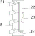
FIG. 2 is a schematic view of the ventilation device of the present invention;
FIG. 3 is a partial schematic view of the present invention;
in the figure: 1. a fin; 2. a fixing plate; 3. a dust screen; 4. a ventilation device; 5. a temperature sensor; 6. a handle; 7. a cover body; 8. a generator body; 9. a rubber layer; 10. a lock handle; 11. a support frame; 12. a return spring; 13. a metal foil; 14. a connecting seat; 15. a through hole; 16. a universal wheel; 17. a locking block; 18. an electric telescopic rod; 19. a groove; 20. a bump; 21. a blind window; 22. a connecting frame; 23. and a single chip microcomputer.
Detailed Description
The technical solutions in the embodiments of the present invention will be described clearly and completely with reference to the accompanying drawings in the embodiments of the present invention, and it is obvious that the described embodiments are only some embodiments of the present invention, not all embodiments. Based on the embodiments in the present invention, all other embodiments obtained by a person skilled in the art without creative work belong to the protection scope of the present invention.
Referring to fig. 1-3, the present invention provides an embodiment: a novel self-radiating generator comprises a ventilation device 4, a cover body 7, a generator body 8 and a support frame 11, wherein return springs 12 are uniformly arranged at the bottom of the support frame 11, one ends of the return springs 12, which are far away from the support frame 11, are connected with connecting seats 14, universal wheels 16 are arranged at the bottom of the connecting seats 14, braking devices are arranged inside the universal wheels 16, the generator body 8 is arranged at the top of the support frame 11, grooves 19 are formed in two sides of the top of the support frame 11, locking blocks 17 are arranged on the outer sides of the support frame 11 at the positions of the grooves 19, the cover body 7 is arranged at the top of the support frame 11, protruding blocks 20 which are matched with the grooves 19 are arranged on two sides of the bottom of the cover body 7, locking handles 10 which are matched with the locking blocks 17 are arranged on the outer sides of the cover body 7 at the positions of the protruding blocks, one side of the metal sheet 13 is connected with a fixed plate 2, through holes 15 are uniformly arranged on the fixed plate 2, a ventilation device 4 is arranged on one side of the cover body 7, a dust screen 3 is arranged on the side wall of the cover body 7 on one side of the ventilation device 4, and one side of the ventilation device 4 is uniformly provided with a shutter 21, the inside of the ventilation device 4 at one side of the shutter 21 is provided with a connecting frame 22, the bottom end inside the ventilation device 4 is provided with an electric telescopic rod 18, and the output end of the electric telescopic rod 18 is connected with the connecting frame 22, the inner side of the ventilation device 4 is provided with a singlechip 23, the type of the single chip 23 can be AT89S51, the single chip 23 is electrically connected with the electric telescopic rod 18, one side of the inner part of the cover body 7 is provided with a temperature sensor 5, the type of the temperature sensor 5 can be WRM-101, the temperature sensor 5 is electrically connected with the single chip microcomputer 23, a rubber layer 9 is arranged on the inner wall of the cover body 7, and handles 6 are arranged on two sides of the top of the cover body 7.
The working principle is as follows: at first move generator body 8 to in the support frame 11, then cover lid 7, in the electricity generation process, foil 13 absorbs the heat, discharge the heat through fin 1, detect the inside temperature through temperature sensor 5 simultaneously, when the high temperature, singlechip 23 control electric telescopic handle 18 drives link 22 and removes, thereby drive shutter 21 and open, increase the circulation of air, dispel the heat, simultaneously through the cooperation between reset spring 12 and the connecting seat 14, eliminate the vibrations that produce in the electricity generation process, play certain cushioning effect, when needing to maintain generator inside, can be through opening lock handle 10, extract lid 7 from recess 19 through handle 6, maintain generator inside.
It is obvious to a person skilled in the art that the invention is not restricted to details of the above-described exemplary embodiments, but that it can be implemented in other specific forms without departing from the spirit or essential characteristics of the invention. The present embodiments are therefore to be considered in all respects as illustrative and not restrictive, the scope of the invention being indicated by the appended claims rather than by the foregoing description, and all changes which come within the meaning and range of equivalency of the claims are therefore intended to be embraced therein. Any reference sign in a claim should not be construed as limiting the claim concerned.
Claims (5)
1. The utility model provides a novel from heat dissipation generator, includes ventilation unit (4), lid (7), generator body (8) and support frame (11), its characterized in that: the generator is characterized in that reset springs (12) are uniformly arranged at the bottom of the support frame (11), one ends, far away from the support frame (11), of the reset springs (12) are connected with connecting seats (14), a generator body (8) is installed at the top of the support frame (11), grooves (19) are formed in two sides of the top of the support frame (11), locking blocks (17) are arranged on the outer sides of the support frame (11) at positions of the grooves (19), a cover body (7) is installed at the top of the support frame (11), protruding blocks (20) matched with the grooves (19) are arranged on two sides of the bottom of the cover body (7), locking handles (10) matched with the locking blocks (17) are arranged on the outer sides of the cover body (7) at positions of the protruding blocks (20), fins (1) are arranged at the tops of the support frame (11) and the cover body (7), one ends of the fins (1) are connected with metal sheets (13), ventilation unit (4) are installed to one side of lid (7), and one side of ventilation unit (4) evenly installs shutter (21), and the inside of ventilation unit (4) of shutter (21) one side is equipped with link (22), electric telescopic handle (18) are installed to the inside bottom of ventilation unit (4), and the output and link (22) of electric telescopic handle (18) are connected, singlechip (23) are installed to the inboard of ventilation unit (4), and singlechip (23) are connected with electric telescopic handle (18) electricity, temperature sensor (5) are installed to the inside one side of lid (7), and temperature sensor (5) and singlechip (23) electric connection, be equipped with rubber layer (9) on the inner wall of lid (7).
2. The novel self-radiating generator of claim 1, wherein: the bottom of the connecting seat (14) is provided with a universal wheel (16), and a braking device is arranged inside the universal wheel (16).
3. The novel self-radiating generator of claim 1, wherein: through holes (15) are uniformly formed in the fixing plate (2).
4. The novel self-radiating generator of claim 1, wherein: handles (6) are arranged on two sides of the top of the cover body (7).
5. The novel self-radiating generator of claim 1, wherein: and a dustproof net (3) is arranged on the side wall of the cover body (7) on one side of the ventilating device (4).
Priority Applications (1)
| Application Number | Priority Date | Filing Date | Title |
|---|---|---|---|
| CN201820532854.8U CN209959348U (en) | 2018-04-16 | 2018-04-16 | Novel self-heat-dissipation generator |
Applications Claiming Priority (1)
| Application Number | Priority Date | Filing Date | Title |
|---|---|---|---|
| CN201820532854.8U CN209959348U (en) | 2018-04-16 | 2018-04-16 | Novel self-heat-dissipation generator |
Publications (1)
| Publication Number | Publication Date |
|---|---|
| CN209959348U true CN209959348U (en) | 2020-01-17 |
Family
ID=69233327
Family Applications (1)
| Application Number | Title | Priority Date | Filing Date |
|---|---|---|---|
| CN201820532854.8U Expired - Fee Related CN209959348U (en) | 2018-04-16 | 2018-04-16 | Novel self-heat-dissipation generator |
Country Status (1)
| Country | Link |
|---|---|
| CN (1) | CN209959348U (en) |
Cited By (1)
| Publication number | Priority date | Publication date | Assignee | Title |
|---|---|---|---|---|
| CN112610378A (en) * | 2020-12-15 | 2021-04-06 | 吉安市裕财机械工程有限公司 | Oil delivery control device of diesel generator |
-
2018
- 2018-04-16 CN CN201820532854.8U patent/CN209959348U/en not_active Expired - Fee Related
Cited By (1)
| Publication number | Priority date | Publication date | Assignee | Title |
|---|---|---|---|---|
| CN112610378A (en) * | 2020-12-15 | 2021-04-06 | 吉安市裕财机械工程有限公司 | Oil delivery control device of diesel generator |
Similar Documents
| Publication | Publication Date | Title |
|---|---|---|
| CN210156447U (en) | Battery protective housing for heat dissipation antidetonation type new energy automobile | |
| CN209562291U (en) | A kind of brushless motor dust-proof radiating cover | |
| CN211174337U (en) | Portable silence generator unit shell | |
| CN212874660U (en) | Storage battery box structure for electric energy storage | |
| CN221979268U (en) | A low-power DCDC controller for new energy vehicles | |
| CN210805884U (en) | New energy automobile battery heat abstractor | |
| CN210926107U (en) | Heat dissipation protection device of new energy battery | |
| CN209786942U (en) | New energy automobile motor protective housing that takes precautions against earthquakes | |
| CN219169858U (en) | Protection mechanism of two-protection welding machine | |
| CN113224897B (en) | Motor with dehumidification function and shock attenuation are effectual | |
| CN110600639A (en) | New energy automobile battery heat dissipation protector | |
| CN216532417U (en) | Monitoring device with shock attenuation and heat dissipation function | |
| CN212671940U (en) | Diesel generating set protective housing | |
| CN210161887U (en) | Electric automobile lithium cell that radiating effect is good | |
| CN211296383U (en) | Motor with dust cover | |
| CN210537235U (en) | Damping shell for electric scooter controller | |
| CN115835554A (en) | Network security cabinet | |
| CN211181799U (en) | Braking resistance box that protectiveness is high | |
| CN211175916U (en) | Generator set shell with anti-collision function | |
| CN220544874U (en) | Novel inverter shell | |
| CN216564685U (en) | Rotor structure for DC motor | |
| CN220042004U (en) | Energy storage battery cooling equipment | |
| CN224054110U (en) | Protective equipment for photovoltaic inverter | |
| CN222735191U (en) | Aluminum alloy frame for new energy vehicle battery pack | |
| CN218513612U (en) | Lithium battery mounting rack |
Legal Events
| Date | Code | Title | Description |
|---|---|---|---|
| GR01 | Patent grant | ||
| GR01 | Patent grant | ||
| CF01 | Termination of patent right due to non-payment of annual fee | ||
| CF01 | Termination of patent right due to non-payment of annual fee |
Granted publication date: 20200117 Termination date: 20210416 |