CN209954395U - Fan blade polisher with waste recovery function - Google Patents
Fan blade polisher with waste recovery function Download PDFInfo
- Publication number
- CN209954395U CN209954395U CN201920771082.8U CN201920771082U CN209954395U CN 209954395 U CN209954395 U CN 209954395U CN 201920771082 U CN201920771082 U CN 201920771082U CN 209954395 U CN209954395 U CN 209954395U
- Authority
- CN
- China
- Prior art keywords
- groove
- base
- sliding groove
- moving vehicle
- fan blade
- Prior art date
- Legal status (The legal status is an assumption and is not a legal conclusion. Google has not performed a legal analysis and makes no representation as to the accuracy of the status listed.)
- Expired - Fee Related
Links
Images


Classifications
-
- Y—GENERAL TAGGING OF NEW TECHNOLOGICAL DEVELOPMENTS; GENERAL TAGGING OF CROSS-SECTIONAL TECHNOLOGIES SPANNING OVER SEVERAL SECTIONS OF THE IPC; TECHNICAL SUBJECTS COVERED BY FORMER USPC CROSS-REFERENCE ART COLLECTIONS [XRACs] AND DIGESTS
- Y02—TECHNOLOGIES OR APPLICATIONS FOR MITIGATION OR ADAPTATION AGAINST CLIMATE CHANGE
- Y02P—CLIMATE CHANGE MITIGATION TECHNOLOGIES IN THE PRODUCTION OR PROCESSING OF GOODS
- Y02P70/00—Climate change mitigation technologies in the production process for final industrial or consumer products
- Y02P70/10—Greenhouse gas [GHG] capture, material saving, heat recovery or other energy efficient measures, e.g. motor control, characterised by manufacturing processes, e.g. for rolling metal or metal working
Landscapes
- Disintegrating Or Milling (AREA)
Abstract
Description
技术领域technical field
本实用新型涉及风机叶片加工技术领域,具体为一种具有废料回收功能的风机叶片打磨机。The utility model relates to the technical field of fan blade processing, in particular to a fan blade grinder with a waste recycling function.
背景技术Background technique
风机叶片,是风力发电机的核心部件之一,约占风机总成本的15%-20%,它设计的好坏将直接关系到风机的性能以及效益,风机叶片的加工影响着工作的效率,打磨机是风机叶片加工中不可缺少的设备。The fan blade is one of the core components of the wind turbine, accounting for about 15%-20% of the total cost of the fan. The quality of its design will directly affect the performance and benefits of the fan. The processing of the fan blade affects the efficiency of the work. Grinder is an indispensable equipment in fan blade processing.
现在市场采用传统的打磨机,不便于固定住风机叶片,不方便调节风机叶片的角度,以及不方便回收打磨中掉下的碎屑。因此,需要一种具有废料回收功能的风机叶片打磨机来改善上述问题。At present, the traditional grinding machine is used in the market, which is inconvenient to fix the fan blades, to adjust the angle of the fan blades, and to recover the debris dropped during grinding. Therefore, there is a need for a fan blade grinder with a waste recycling function to improve the above problems.
实用新型内容Utility model content
本实用新型的目的在于提供一种具有废料回收功能的风机叶片打磨机,以解决上述背景技术中提出的传统的打磨机台,不便于固定住风机叶片,不方便调节风机叶片的角度,以及不方便回收打磨中掉下的碎屑的问题。The purpose of this utility model is to provide a fan blade grinding machine with waste recycling function, in order to solve the traditional grinding machine proposed in the above-mentioned background technology, it is inconvenient to fix the fan blade, it is inconvenient to adjust the angle of the fan blade, and it is not convenient to fix the fan blade. It is convenient for the problem of recycling the debris that fell during sanding.
为实现上述目的,本实用新型提供如下技术方案:一种具有废料回收功能的风机叶片打磨机,包括底座、旋转柱、滑槽、滚筒、第二凹槽、液压缸和通孔,所述底座上端面设置有电机台,且电机台上设置有电机,同时电机上设置有电机轴,所述旋转柱设置在电机轴右端,且旋转柱贯穿支架,所述支架设置在底座上,且支架设置在电机台右侧,所述旋转柱右端设置有固定盘,且固定盘上贯穿有螺栓,所述滑槽开设在底座上,且滑槽设置在支架右侧,同时滑槽内设置有移动车,所述移动车下端通过滚轮与滑槽相接触,且移动车上端面开设有第一凹槽,所述滚筒设置在第一凹槽侧壁上,且滚筒设置在第一收集盒上方,同时第一收集盒设置在第一凹槽底部,所述第二凹槽开设在移动车上端面,且第二凹槽设置在第一凹槽外侧,同时第二凹槽内设置有打磨机主体,所述液压缸设置在底座内,且液压缸设置在滑槽右侧,所述液压缸上设置有液压杆,且液压杆贯穿滑槽右端,同时液压杆左端与移动车右端面相连接,所述通孔开设在底座前端面,且通孔后端与滑槽左端相连接,同时通孔内设置有第二收集盒。In order to achieve the above purpose, the utility model provides the following technical solutions: a fan blade grinder with a waste recycling function, comprising a base, a rotating column, a chute, a roller, a second groove, a hydraulic cylinder and a through hole, the base A motor table is arranged on the upper end face, and a motor is arranged on the motor table, and a motor shaft is arranged on the motor at the same time. On the right side of the motor table, the right end of the rotating column is provided with a fixed plate, and bolts are inserted through the fixed plate, the chute is opened on the base, and the chute is arranged on the right side of the bracket, and a mobile cart is arranged in the chute , the lower end of the moving car is in contact with the chute through the roller, and the upper end face of the moving car is provided with a first groove, the roller is arranged on the side wall of the first groove, and the roller is arranged above the first collection box, and at the same time The first collection box is arranged at the bottom of the first groove, the second groove is opened on the upper end face of the moving vehicle, the second groove is arranged outside the first groove, and the grinder main body is arranged in the second groove, The hydraulic cylinder is arranged in the base, and the hydraulic cylinder is arranged on the right side of the chute, the hydraulic cylinder is provided with a hydraulic rod, and the hydraulic rod penetrates the right end of the chute, and the left end of the hydraulic rod is connected with the right end face of the moving vehicle, the The through hole is opened on the front end surface of the base, the rear end of the through hole is connected with the left end of the chute, and a second collection box is arranged in the through hole.
优选的,所述旋转柱与支架构成转动机构。Preferably, the rotating column and the bracket constitute a rotating mechanism.
优选的,所述螺栓呈环形阵列分布在固定盘上,且固定盘轴线与旋转柱轴线重合。Preferably, the bolts are distributed on the fixed plate in an annular array, and the axis of the fixed plate coincides with the axis of the rotating column.
优选的,所述移动车通过滚轮与滑槽构成滑动机构,且滚轮三个设置为一组。Preferably, the moving vehicle forms a sliding mechanism through rollers and chute, and three rollers are arranged in a group.
优选的,所述滚筒与移动车构成转动机构,且滚筒等距离分布在移动车上。Preferably, the rollers and the moving vehicle form a rotating mechanism, and the rollers are distributed on the moving vehicle at equal distances.
优选的,所述打磨机主体设置有两个,且打磨机主体关于移动车中轴线对称设置。Preferably, there are two grinding machine main bodies, and the grinding machine main bodies are arranged symmetrically with respect to the central axis of the moving vehicle.
与现有技术相比,本实用新型的有益效果是:该具有废料回收功能的风机叶片打磨机,Compared with the prior art, the beneficial effects of the present utility model are: the fan blade grinder with the waste recycling function,
(1)设置有螺栓、固定盘和移动车,通过螺栓将风机叶片固定在固定盘上,以固定住风机叶片,在移动车的支撑下,加强风机叶片的稳定性,起到方便固定的目的;(1) There are bolts, a fixed plate and a mobile car. The fan blades are fixed on the fixed plate by bolts to fix the fan blades. Under the support of the mobile car, the stability of the fan blades is strengthened, which is convenient for fixing. ;
(2)设置有电机和电机轴,在电机的作用下,通过电机轴带动旋转柱转动,使固定盘带动风机叶片转动,以调节风机叶片的角度,以便于操作人员对风机叶片进行打磨;(2) A motor and a motor shaft are provided. Under the action of the motor, the rotating column is driven by the motor shaft to rotate, so that the fixed disc drives the fan blade to rotate, so as to adjust the angle of the fan blade, so that the operator can polish the fan blade;
(3)设置有第一收集盒、通孔和第二收集盒,打磨产生的碎屑大部分掉落到移动车上,并且进入第一收集盒内,少部分掉入底座上,将底座上的碎屑扫进滑槽内的通孔内,最后掉入第二收集盒内,已达到方便收集碎屑的目的。(3) A first collection box, a through hole and a second collection box are provided. Most of the debris generated by grinding falls on the moving vehicle and enters the first collection box, and a small part falls into the base. The debris is swept into the through hole in the chute, and finally falls into the second collection box, which has achieved the purpose of collecting debris conveniently.
附图说明Description of drawings
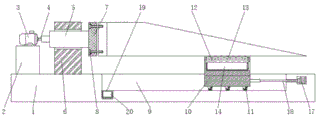
图1为本实用新型主视剖面结构示意图;Fig. 1 is the front view sectional structure schematic diagram of the utility model;
图2为本实用新型主视结构示意图;Fig. 2 is the front view structure schematic diagram of the utility model;
图3为本实用新型俯视结构示意图;Fig. 3 is the top view structure schematic diagram of the utility model;
图4为本实用新型固定盘和螺栓连接结构示意图。FIG. 4 is a schematic diagram of the fixing plate and the bolt connection structure of the present invention.
图中:1、底座,2、电机台,3、电机,4、电机轴,5、旋转柱,6、支架,7、固定盘,8、螺栓,9、滑槽,10、移动车,11、滚轮,12、第一凹槽,13、滚筒,14、第一收集盒,15、第二凹槽,16、打磨机主体,17、液压缸,18、液压杆,19、通孔,20、第二收集盒。In the picture: 1, base, 2, motor table, 3, motor, 4, motor shaft, 5, rotating column, 6, bracket, 7, fixed plate, 8, bolt, 9, chute, 10, mobile cart, 11 , roller, 12, first groove, 13, roller, 14, first collection box, 15, second groove, 16, grinder body, 17, hydraulic cylinder, 18, hydraulic rod, 19, through hole, 20 , the second collection box.
具体实施方式Detailed ways
下面将结合本实用新型实施例中的附图,对本实用新型实施例中的技术方案进行清楚、完整地描述,显然,所描述的实施例仅仅是本实用新型一部分实施例,而不是全部的实施例。基于本实用新型中的实施例,本领域普通技术人员在没有做出创造性劳动前提下所获得的所有其他实施例,都属于本实用新型保护的范围。The technical solutions in the embodiments of the present utility model will be clearly and completely described below with reference to the accompanying drawings in the embodiments of the present utility model. Obviously, the described embodiments are only a part of the embodiments of the present utility model, rather than all the implementations. example. Based on the embodiments of the present invention, all other embodiments obtained by those of ordinary skill in the art without creative work fall within the protection scope of the present invention.
请参阅图1-4,本实用新型提供一种技术方案:一种具有废料回收功能的风机叶片打磨机,根据图1、图2和图4所示,底座1上端面设置有电机台2,且电机台2上设置有电机3,同时电机3上设置有电机轴4,旋转柱5设置在电机轴4右端,且旋转柱5贯穿支架6,旋转柱5与支架6构成转动机构,旋转柱5转动,可带动风机叶片转动,以调节风机叶片角度,方便人员打磨,支架6设置在底座1上,且支架6设置在电机台2右侧,旋转柱5右端设置有固定盘7,且固定盘7上贯穿有螺栓8,螺栓8呈环形阵列分布在固定盘7上,且固定盘7轴线与旋转柱5轴线重合,通过螺栓8将风机叶片固定在固定盘7上,滑槽9开设在底座1上,且滑槽9设置在支架6右侧,同时滑槽9内设置有移动车10。Please refer to FIGS. 1-4, the present utility model provides a technical solution: a fan blade grinder with waste recycling function, according to FIG. 1, FIG. 2 and FIG. 4, the upper end surface of the base 1 is provided with a motor table 2, And the motor table 2 is provided with a motor 3, and at the same time, the motor 3 is provided with a motor shaft 4, a rotating column 5 is arranged on the right end of the motor shaft 4, and the rotating column 5 penetrates the bracket 6, and the rotating column 5 and the bracket 6 constitute a rotating mechanism, and the rotating column 5 rotation, can drive the fan blade to rotate, to adjust the angle of the fan blade, convenient for personnel grinding, the bracket 6 is arranged on the base 1, and the bracket 6 is arranged on the right side of the motor table 2, the right end of the rotating column 5 is provided with a fixed plate 7, and fixed There are
根据图1、图2和图3所示,移动车10下端通过滚轮11与滑槽9相接触,且移动车10上端面开设有第一凹槽12,移动车10通过滚轮11与滑槽9构成滑动机构,且滚轮11三个设置为一组,移动车10支撑住风机叶片右端,以加强风机叶片的稳定性,滚筒13设置在第一凹槽12侧壁上,且滚筒13设置在第一收集盒14上方,同时第一收集盒14设置在第一凹槽12底部,第一收集盒14可从移动车10的右侧抽出,滚筒13与移动车10构成转动机构,且滚筒13等距离分布在移动车10上,方便移动车10在风机叶片下方移动,第二凹槽15开设在移动车10上端面,且第二凹槽15设置在第一凹槽12外侧,同时第二凹槽15内设置有打磨机主体16,打磨机主体16设置有两个,且打磨机主体16关于移动车10中轴线对称设置,操作人员可拿起打磨机主体16对风机叶片进行打磨,液压缸17设置在底座1内,且液压缸17设置在滑槽9右侧,液压缸17上设置有液压杆18,且液压杆18贯穿滑槽9右端,同时液压杆18左端与移动车10右端面相连接,通孔19开设在底座1前端面,且通孔19后端与滑槽9左端相连接,同时通孔19内设置有第二收集盒20。As shown in FIGS. 1 , 2 and 3 , the lower end of the moving
工作原理:在使用该具有废料回收功能的风机叶片打磨机时,将风机叶片放到移动车10上,将液压缸17和电机3连接外部电源,启动液压缸17,液压缸17带动液压杆18移动,从而使液压杆18顶着移动车10在滑槽9内移动,将风电叶片移动到固定盘7旁,通过螺栓8将风机叶片固定在固定盘7上,以固定住风机叶片,在风电叶片的某个地方打磨,就将移动车10移动到下方,操作人员拿出打磨机主体16,打磨机主体16为现有技术,且打磨机主体16在本申请文件中仅为示意作用,不作为本申请文件的新颖点和保护点,可进行打磨,打磨产生了碎屑掉入移动车10上的第一收集盒14内,已达到收集碎屑的目的,当要调节风机叶片的角度时,启动电机3,电机3带动电机轴4转动,使旋转柱5通过固定盘7带动风机叶片旋转,以调节风机叶片的角度,少部分碎屑掉到底座1上,将底座1上的碎屑扫进滑槽9内的通孔19内,最后掉入第二收集盒20内,最后向前取出第一收集盒14以及向右取出第二收集盒20进行清理即可,本说明书中未作详细描述的内容属于本领域专业技术人员公知的现有技术。Working principle: When using the fan blade grinder with waste recycling function, put the fan blade on the
术语“中心”、“纵向”、“横向”、“前”、“后”、“左”、“右”、“竖直”、“水平”、“顶”、“底”、“内”、“外”等指示的方位或位置关系为基于附图所示的方位或位置关系,仅是为便于描述本实用新型的简化描述,而不是指示或暗指所指的装置或元件必须具有特定的方位、为特定的方位构造和操作,因而不能理解为对本实用新型保护内容的限制。The terms "center", "portrait", "horizontal", "front", "rear", "left", "right", "vertical", "horizontal", "top", "bottom", "inner", The orientation or positional relationship indicated by "outside" is based on the orientation or positional relationship shown in the accompanying drawings, and is only a simplified description for the convenience of describing the present invention, rather than indicating or implying that the indicated device or element must have a specific Orientation, construction and operation are specific orientations, and therefore should not be construed as limiting the protection content of the present invention.
尽管参照前述实施例对本实用新型进行了详细的说明,对于本领域的技术人员来说,其依然可以对前述各实施例所记载的技术方案进行修改,或者对其中部分技术特征进行等同替换,凡在本实用新型的精神和原则之内,所作的任何修改、等同替换、改进等,均应包含在本实用新型的保护范围之内。Although the present invention has been described in detail with reference to the foregoing embodiments, for those skilled in the art, it is still possible to modify the technical solutions described in the foregoing embodiments, or perform equivalent replacements for some of the technical features. Within the spirit and principle of the present utility model, any modifications, equivalent replacements, improvements, etc. made shall be included within the protection scope of the present utility model.
Claims (6)
Priority Applications (1)
| Application Number | Priority Date | Filing Date | Title |
|---|---|---|---|
| CN201920771082.8U CN209954395U (en) | 2019-05-27 | 2019-05-27 | Fan blade polisher with waste recovery function |
Applications Claiming Priority (1)
| Application Number | Priority Date | Filing Date | Title |
|---|---|---|---|
| CN201920771082.8U CN209954395U (en) | 2019-05-27 | 2019-05-27 | Fan blade polisher with waste recovery function |
Publications (1)
| Publication Number | Publication Date |
|---|---|
| CN209954395U true CN209954395U (en) | 2020-01-17 |
Family
ID=69246801
Family Applications (1)
| Application Number | Title | Priority Date | Filing Date |
|---|---|---|---|
| CN201920771082.8U Expired - Fee Related CN209954395U (en) | 2019-05-27 | 2019-05-27 | Fan blade polisher with waste recovery function |
Country Status (1)
| Country | Link |
|---|---|
| CN (1) | CN209954395U (en) |
-
2019
- 2019-05-27 CN CN201920771082.8U patent/CN209954395U/en not_active Expired - Fee Related
Similar Documents
| Publication | Publication Date | Title |
|---|---|---|
| CN108857623B (en) | Long pipeline inner wall equipment of polishing | |
| CN216657432U (en) | Switch is wearing and tearing machine for apron | |
| CN211872529U (en) | Highway road surface grinding device | |
| CN211103097U (en) | Sanding machine | |
| CN218697197U (en) | Deburring device | |
| CN218613186U (en) | Panel equipment of polishing with dust absorption function | |
| CN214135485U (en) | Multi-angle polishing machine with dust collecting device | |
| CN211639338U (en) | Rotary type plane lapping machine for spherical workpiece | |
| CN219444484U (en) | Yaw shaft polisher | |
| CN221416007U (en) | Wall grinding device for construction | |
| CN216577170U (en) | Automatic polishing machine | |
| CN219275460U (en) | Polisher with dust suction channel | |
| CN222711781U (en) | A double-head grinding machine | |
| CN223506901U (en) | A grinding machine for machining | |
| CN222726250U (en) | Precision adjustable heel grinding machine | |
| CN221871500U (en) | Wall polisher | |
| CN221792009U (en) | A superfine surface grinder with dust removal function | |
| CN217942915U (en) | A hard alloy blade polishing tool | |
| CN220825860U (en) | A pounding machine convenient for cleaning waste residue | |
| CN217619752U (en) | Polishing and grinding device of industrial robot platform | |
| CN218284804U (en) | A tool polishing machine capable of cleaning debris | |
| CN216327111U (en) | Granite stone facing burnishing device | |
| CN224254966U (en) | Diamond saw blade grinding device | |
| CN218427612U (en) | Timber opposite sex burnishing machine | |
| CN220993980U (en) | Stainless steel product polisher |
Legal Events
| Date | Code | Title | Description |
|---|---|---|---|
| GR01 | Patent grant | ||
| GR01 | Patent grant | ||
| CF01 | Termination of patent right due to non-payment of annual fee |
Granted publication date: 20200117 |
|
| CF01 | Termination of patent right due to non-payment of annual fee |