CN209944764U - Electric heating control system efficiently utilizing photovoltaic direct heat - Google Patents
Electric heating control system efficiently utilizing photovoltaic direct heat Download PDFInfo
- Publication number
- CN209944764U CN209944764U CN201822024190.7U CN201822024190U CN209944764U CN 209944764 U CN209944764 U CN 209944764U CN 201822024190 U CN201822024190 U CN 201822024190U CN 209944764 U CN209944764 U CN 209944764U
- Authority
- CN
- China
- Prior art keywords
- heating
- heat
- photovoltaic
- heat storage
- water
- Prior art date
- Legal status (The legal status is an assumption and is not a legal conclusion. Google has not performed a legal analysis and makes no representation as to the accuracy of the status listed.)
- Active
Links
Images


Classifications
-
- Y—GENERAL TAGGING OF NEW TECHNOLOGICAL DEVELOPMENTS; GENERAL TAGGING OF CROSS-SECTIONAL TECHNOLOGIES SPANNING OVER SEVERAL SECTIONS OF THE IPC; TECHNICAL SUBJECTS COVERED BY FORMER USPC CROSS-REFERENCE ART COLLECTIONS [XRACs] AND DIGESTS
- Y02—TECHNOLOGIES OR APPLICATIONS FOR MITIGATION OR ADAPTATION AGAINST CLIMATE CHANGE
- Y02E—REDUCTION OF GREENHOUSE GAS [GHG] EMISSIONS, RELATED TO ENERGY GENERATION, TRANSMISSION OR DISTRIBUTION
- Y02E10/00—Energy generation through renewable energy sources
- Y02E10/50—Photovoltaic [PV] energy
Landscapes
- Heat-Pump Type And Storage Water Heaters (AREA)
Abstract
一种高效利用光伏直热的电加热控制系统,储热部分包括储热内胆,在储热内胆内设有直流电加热管和交流电加热管,储热内胆外设有为直流电加热管供电的光伏组件和为交流电加热管供电的交流电源;所述直流宽电压输入控制电路部分包括AC/DC电源转换模块、直流继电器、热断路器、和自恢复温控器;所述高效光伏直热逻辑控制部分包含待机状态和即热状态,在待机状态由光伏组件提供电能加热储热内胆中的水;在即热状态下,由光伏加热和市电加热同时工作,达到预设水温,自动转为光伏加热。本实用新型可最大化的将光伏直流电能转换为储水热能,提高绿色能源利用;并通过提高储水的水温,增加电热水器的等效容量。
An electric heating control system for efficiently utilizing photovoltaic direct heat. The photovoltaic module and the AC power supply for the AC heating tube; the DC wide voltage input control circuit part includes an AC/DC power conversion module, a DC relay, a thermal circuit breaker, and a self-recovery thermostat; the high-efficiency photovoltaic direct heat The logic control part includes a standby state and an instant heating state. In the standby state, the photovoltaic module provides electrical energy to heat the water in the heat storage tank; in the instant heating state, the photovoltaic heating and the mains heating work at the same time to reach the preset water temperature and automatically turn Heating for photovoltaics. The utility model can maximize the conversion of photovoltaic direct current electric energy into stored water thermal energy, thereby improving the utilization of green energy; and by increasing the water temperature of the stored water, the equivalent capacity of the electric water heater can be increased.
Description
技术领域technical field
本实用新型涉及一种光利用技术,特别是一种高效利用光伏直热的电加热控制系统。The utility model relates to a light utilization technology, in particular to an electric heating control system for efficiently utilizing photovoltaic direct heat.
背景技术Background technique
光伏是一种光电利用,将太阳能的辐射能直接转换为直流电能,全程无机械传动,零碳排放,寿命长达25年,是一种绿色清洁能源。光伏和电热水器的结合,利用光伏组件代替太阳能集热器,发电提供给电热水器加热管,即有太阳能热水器的绿色节能环保的功能,又有电热水器的便捷。Photovoltaic is a kind of photoelectric utilization, which directly converts the radiant energy of solar energy into direct current electricity. It has no mechanical transmission in the whole process, zero carbon emission, and has a life span of up to 25 years. It is a kind of green and clean energy. The combination of photovoltaic and electric water heaters uses photovoltaic modules to replace solar collectors, and provides electricity to the heating pipes of electric water heaters.
但光伏输出直流电的电压随着光照强度变化而波动,现有的光伏直热电热水器只能利用某一电压范围内光伏直流电能,存在光伏直热利用率低的问题。However, the voltage of the photovoltaic output DC power fluctuates with the change of the light intensity. The existing photovoltaic direct heat electric water heater can only utilize photovoltaic direct current power within a certain voltage range, and there is a problem of low utilization rate of photovoltaic direct heat.
发明内容SUMMARY OF THE INVENTION
本实用新型要解决的技术问题是针对现有技术的不足,提出了一种高效利用光伏直热的电加热控制系统,可大大提高光伏直热的利用率。The technical problem to be solved by the utility model is to aim at the deficiencies of the prior art, and proposes an electric heating control system that efficiently utilizes the photovoltaic direct heat, which can greatly improve the utilization rate of the photovoltaic direct heat.
本实用新型要解决的技术问题是通过以下技术方案来实现的,一种高效利用光伏直热的电加热控制系统,其特点是:包括储热部分、直流宽电压输入控制电路部分和高效光伏直热逻辑控制部分,The technical problem to be solved by the present utility model is achieved through the following technical solutions, an electric heating control system for efficiently utilizing photovoltaic direct heat, which is characterized by: including a heat storage part, a DC wide voltage input control circuit part and a high-efficiency photovoltaic direct heat Thermal logic control section,
所述储热部分包括储热内胆,在储热内胆内设有直流电加热管和交流电加热管,储热内胆外设有为直流电加热管供电的光伏组件和为交流电加热管供电的交流电源;The heat storage part includes a heat storage inner tank, a direct current heating pipe and an alternating current heating pipe are arranged in the heat storage inner tank, and a photovoltaic component for supplying power to the direct current heating pipe and an AC power supply for the alternating current heating pipe are arranged outside the heat storage inner tank. power supply;
所述直流宽电压输入控制电路部分包括AC/DC电源转换模块、直流继电器、热断路器、和自恢复温控器,交流电源经AC/DC电源转换模块给直流继电器的线圈供电,提供控制光伏直流电通断的电能;热断路器通过检测储热内胆内水的温度,在超过安全温度T1时,断开直流电路,(保护电热水器安全。)自恢复温控器可设定温度T2(T2须小于T1),当储水水温达到T2时,自恢复温控器断开直流电路;The DC wide voltage input control circuit part includes an AC/DC power conversion module, a DC relay, a thermal circuit breaker, and a self-recovery thermostat. The electric energy of the direct current on and off; the thermal circuit breaker detects the temperature of the water in the heat storage tank, and when the safe temperature T1 is exceeded, the direct current circuit is disconnected (to protect the safety of the electric water heater.) The self-recovery thermostat can set the temperature T2 ( T2 must be less than T1), when the storage water temperature reaches T2, the self-recovery thermostat disconnects the DC circuit;
所述高效光伏直热逻辑控制部分包含待机状态和即热状态:The high-efficiency photovoltaic direct heating logic control part includes a standby state and an instant heating state:
在待机状态下,经过直流宽电压输入控制电路,光伏组件的直流电能在0V至额定电压范围内可全部供给直流电加热管,加热储热内胆中的水;In the standby state, through the DC wide voltage input control circuit, the DC power of the photovoltaic module can be fully supplied to the DC heating tube within the range of 0V to the rated voltage to heat the water in the heat storage tank;
在即热状态下,交流电加热管和直流电加热管同时工作,加热储热内胆中的水,快速达到预设水温,然后交流电加热管停止工作,直流电加热管继续加热,持续提高储热内胆中的水温,直至达到设定的极限温度后,在直流宽电压输入控制电路控制下中断。In the instant heating state, the AC heating tube and the DC heating tube work at the same time to heat the water in the heat storage liner and quickly reach the preset water temperature, and then the AC heating tube stops working, and the DC heating tube continues to heat, continuously improving the heat storage liner. After reaching the set limit temperature, it will be interrupted under the control of the DC wide voltage input control circuit.
本实用新型要解决的技术问题还可以通过以下技术方案来进一步实现,直流电加热管单独安装在法兰盘上,或与交流电加热管集成在一个法兰上,组成交直流集成加热器。The technical problem to be solved by the utility model can be further realized by the following technical solutions: the DC electric heating tube is installed on the flange alone, or integrated with the AC electric heating tube on a flange to form an AC-DC integrated heater.
本实用新型要解决的技术问题还可以通过以下技术方案来进一步实现,储热内胆为双胆组合结构。The technical problem to be solved by the utility model can also be further realized by the following technical solutions, the heat storage inner tank is a double tank combined structure.
本实用新型要解决的技术问题还可以通过以下技术方案来进一步实现,自恢复温控器可设定温度T2小于所述安全温度T1。The technical problem to be solved by the present invention can be further realized by the following technical solutions, the self-recovery temperature controller can set the temperature T2 to be lower than the safety temperature T1.
本实用新型与现有技术相比,包含了直流宽电压输入控制电路和高效光伏直热逻辑控制,可提高光伏电热水器光伏发电直流电压可利用范围,并最大化的将光伏直流电能转换为储水热能,提高绿色能源利用;并通过提高储水的水温,增加电热水器的等效容量。Compared with the prior art, the utility model includes a DC wide voltage input control circuit and a high-efficiency photovoltaic direct heating logic control, which can increase the available range of the photovoltaic power generation direct current voltage of the photovoltaic electric water heater, and maximize the conversion of photovoltaic direct current electric energy into storage Water thermal energy, improve the utilization of green energy; and increase the equivalent capacity of the electric water heater by increasing the water temperature of the water storage.
附图说明Description of drawings
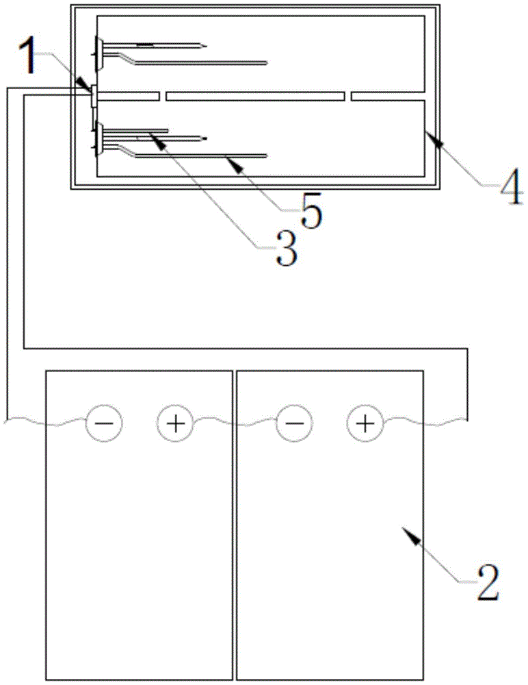
图1为本实用新型的结构简图;Fig. 1 is the structural sketch map of the present utility model;
图2为直流宽电压输入控制电路;Figure 2 is a DC wide voltage input control circuit;
图3为高效光伏直热逻辑控制框图。Figure 3 is a block diagram of high-efficiency photovoltaic direct heating logic control.
具体实施方式Detailed ways
以下进一步描述本实用新型的具体技术方案,以便于本领域的技术人员进一步地理解本实用新型,而不构成对其权利的限制。The specific technical solutions of the present invention are further described below, so as to facilitate those skilled in the art to further understand the present invention, but not to limit the rights thereof.
一种高效利用光伏直热的电加热控制系统,包括储热部分、直流宽电压输入控制电路部分和高效光伏直热逻辑控制部分,An electric heating control system for efficiently utilizing photovoltaic direct heat, comprising a heat storage part, a DC wide voltage input control circuit part and a high-efficiency photovoltaic direct heat logic control part,
所述储热部分包括储热内胆,在储热内胆内设有直流电加热管和交流电加热管,储热内胆外设有为直流电加热管供电的光伏组件和为交流电加热管供电的交流电源;The heat storage part includes a heat storage inner tank, a direct current heating pipe and an alternating current heating pipe are arranged in the heat storage inner tank, and a photovoltaic component for supplying power to the direct current heating pipe and an AC power supply for the alternating current heating pipe are arranged outside the heat storage inner tank. power supply;
所述直流宽电压输入控制电路部分包括AC/DC电源转换模块、直流继电器、热断路器、和自恢复温控器,交流电源经AC/DC电源转换模块给直流继电器的线圈供电,提供控制光伏直流电通断的电能;热断路器通过检测储热内胆内水的温度,在超过安全温度T1时,断开直流电路,保护热水器安全。自恢复温控器可设定温度T2,当储水水温达到T2时,自恢复温控器断开直流电路;The DC wide voltage input control circuit part includes an AC/DC power conversion module, a DC relay, a thermal circuit breaker, and a self-recovery thermostat. The AC power supply supplies power to the coil of the DC relay through the AC/DC power conversion module to provide control photovoltaic The electric energy of the direct current on and off; the thermal circuit breaker detects the temperature of the water in the heat storage tank, and when the safe temperature T1 is exceeded, the direct current circuit is disconnected to protect the safety of the water heater. The self-recovery thermostat can set the temperature T2. When the storage water temperature reaches T2, the self-recovery thermostat disconnects the DC circuit;
所述高效光伏直热逻辑控制部分包含待机状态和即热状态:The high-efficiency photovoltaic direct heating logic control part includes a standby state and an instant heating state:
在待机状态下,经过直流宽电压输入控制电路,光伏组件的直流电能在0V至额定电压范围内可全部供给直流电加热管,加热储热内胆中的水;In the standby state, through the DC wide voltage input control circuit, the DC power of the photovoltaic module can be fully supplied to the DC heating tube within the range of 0V to the rated voltage to heat the water in the heat storage tank;
在即热状态下,交流电加热管和直流电加热管同时工作,加热储热内胆中的水,快速达到预设水温,然后交流电加热管停止工作,直流电加热管继续加热,持续提高储热内胆中的水温,直至达到设定的极限温度后,在直流宽电压输入控制电路控制下中断。In the instant hot state, the AC heating tube and the DC heating tube work at the same time to heat the water in the heat storage liner and quickly reach the preset water temperature, then the AC heating tube stops working, and the DC heating tube continues to heat, continuously improving the heat storage liner. After reaching the set limit temperature, it will be interrupted under the control of the DC wide voltage input control circuit.
直流电加热管单独安装在法兰盘上,或与交流电加热管集成在一个法兰上,组成交直流集成加热器。The DC heating tube is installed on the flange alone, or integrated with the AC heating tube on a flange to form an AC/DC integrated heater.
储热内胆单胆为双胆组合结构。双胆相互联通,直流电加热管和交流电加热管可以分别设置在不同内胆中。The heat storage liner has a single liner with a double liner combined structure. The double bladders are connected to each other, and the direct current heating tube and the alternating current heating tube can be respectively arranged in different inner bladders.
自恢复温控器可设定温度T2小于所述安全温度T1。The self-recovery thermostat can set the temperature T2 to be lower than the safe temperature T1.
具体的:specific:
直流宽电压输入控制电路(1)由AC/DC电源转换模块(8)、直流继电器(9)、热断路器(10)、和自恢复温控器(11)组成。交流电经AC/DC电源转换模块(8)给直流继电器(9)线圈供电,提供控制光伏直流电通断的电能。热断路器(10)通过检测内胆中水的温度,在超过安全温度T1时,断开直流电路,保护电热水器安全。自恢复温控器(11)可设定温度T2(T2须小于T1),当储水水温达到T2时,自恢复温控器(11)断开直流电路。The DC wide voltage input control circuit (1) is composed of an AC/DC power conversion module (8), a DC relay (9), a thermal circuit breaker (10), and a self-recovery thermostat (11). The alternating current supplies power to the coil of the direct current relay (9) through the AC/DC power conversion module (8), and provides electric energy for controlling the on-off of the photovoltaic direct current. The thermal circuit breaker (10) disconnects the direct current circuit by detecting the temperature of the water in the inner tank and when the safe temperature T1 is exceeded, so as to protect the safety of the electric water heater. The self-recovery thermostat (11) can set the temperature T2 (T2 must be less than T1). When the storage water temperature reaches T2, the self-recovery thermostat (11) disconnects the DC circuit.
高效光伏直热逻辑控制部分包含两种状态:待机状态和即热状态。The high-efficiency photovoltaic direct heating logic control part includes two states: standby state and instant heating state.
在待机状态下,经过直流宽电压输入控制电路(1),光伏组件(2)的直流电能在0V至额定电压范围内可全部供给直流电加热管(3),加热储热内胆(4)中储水。In the standby state, through the DC wide voltage input control circuit (1), the DC power of the photovoltaic module (2) can be fully supplied to the DC heating tube (3) within the range of 0V to the rated voltage, heating the heat storage tank (4). water storage.
在即热状态下,交流电加热管(5)和直流电加热管(3)同时工作,加热储热内胆(4)中储水,快速达到预设水温。此后交流电加热管停止工作,直流电加热管(3)持续加热,继续提高储热内胆中储水水温,直至达到设定极限温度后,在直流宽电压输入控制电路(1)控制下中断。In the instant heating state, the alternating current heating tube (5) and the direct current heating tube (3) work simultaneously to heat the water stored in the heat storage inner tank (4) to quickly reach the preset water temperature. After that, the AC heating tube stops working, the DC heating tube (3) continues to heat, and continues to increase the temperature of the water stored in the heat storage liner until it reaches the set limit temperature, and is interrupted under the control of the DC wide voltage input control circuit (1).
直流电加热管(3)单独安装在法兰盘上,或与交流电加热管集成在一个法兰上,组成交直流集成加热器。储热内胆(4)是单胆电热水器,或者是由两个内胆组成双胆速热电热水器。The DC electric heating tube (3) is installed on the flange plate alone, or integrated with the AC electric heating tube on a flange to form an AC-DC integrated heater. The heat-storage inner tank (4) is a single-tank electric water heater, or a double-tank fast-heating electric water heater composed of two inner tanks.
光伏组件(2)在不同光照条件下,工作电压在0至额定电压之间波动,通过直流宽电压输入控制电路(1)可全部提供给直流加热管(3)利用,提高光伏电热水器光伏发电直流电压可利用范围。Under different lighting conditions, the working voltage of the photovoltaic module (2) fluctuates between 0 and the rated voltage. Through the DC wide voltage input control circuit (1), it can be fully supplied to the DC heating tube (3) for use, so as to improve the photovoltaic power generation of the photovoltaic electric water heater. DC voltage available range.
在即热模式下,启用市电交流供给交流加热管(5)加热双胆储水箱(3)中水的同时,并没有切断直流加热电路,光伏组件(2)发出直流电经过直流宽电压输入控制电路(1)供给直流加热管(3),同时加热储水,可提高达到预设水温的速度。In the instant heating mode, the AC heating tube (5) of the AC supply from the commercial power is used to heat the water in the double-tank water storage tank (3), while the DC heating circuit is not cut off, and the photovoltaic module (2) sends out DC power through the DC wide voltage input control circuit (1) Supplying the DC heating tube (3) and heating the storage water at the same time can increase the speed of reaching the preset water temperature.
在即热模式下,当储水达到预设温度后,交流加热停止工作。此时直流加热电路依然工作,直至达到电热水箱极限温度后,直流宽电压输入控制电路(1)切断直流供给。此工作方式可最大化将光伏电能转换为储水热能,提高绿色能源利用;并通过提高储水的水温,增加电热水器的等效容量。In the instant heating mode, when the stored water reaches the preset temperature, the AC heating stops working. At this time, the DC heating circuit still works until the limit temperature of the electric hot water tank is reached, and the DC wide voltage input control circuit (1) cuts off the DC supply. This working method can maximize the conversion of photovoltaic electric energy into stored water thermal energy, improve the utilization of green energy; and increase the equivalent capacity of the electric water heater by increasing the water temperature of the stored water.
Claims (4)
Priority Applications (1)
| Application Number | Priority Date | Filing Date | Title |
|---|---|---|---|
| CN201822024190.7U CN209944764U (en) | 2018-12-04 | 2018-12-04 | Electric heating control system efficiently utilizing photovoltaic direct heat |
Applications Claiming Priority (1)
| Application Number | Priority Date | Filing Date | Title |
|---|---|---|---|
| CN201822024190.7U CN209944764U (en) | 2018-12-04 | 2018-12-04 | Electric heating control system efficiently utilizing photovoltaic direct heat |
Publications (1)
| Publication Number | Publication Date |
|---|---|
| CN209944764U true CN209944764U (en) | 2020-01-14 |
Family
ID=69118576
Family Applications (1)
| Application Number | Title | Priority Date | Filing Date |
|---|---|---|---|
| CN201822024190.7U Active CN209944764U (en) | 2018-12-04 | 2018-12-04 | Electric heating control system efficiently utilizing photovoltaic direct heat |
Country Status (1)
| Country | Link |
|---|---|
| CN (1) | CN209944764U (en) |
Cited By (2)
| Publication number | Priority date | Publication date | Assignee | Title |
|---|---|---|---|---|
| CN113137762A (en) * | 2020-01-20 | 2021-07-20 | 青岛海尔智能技术研发有限公司 | Over-temperature protection circuit and power supply circuit of direct current water heater and direct current water heater |
| CN115615004A (en) * | 2022-10-19 | 2023-01-17 | 山东沐阳新能源有限公司 | A wide voltage segmental heating photovoltaic water heater |
-
2018
- 2018-12-04 CN CN201822024190.7U patent/CN209944764U/en active Active
Cited By (2)
| Publication number | Priority date | Publication date | Assignee | Title |
|---|---|---|---|---|
| CN113137762A (en) * | 2020-01-20 | 2021-07-20 | 青岛海尔智能技术研发有限公司 | Over-temperature protection circuit and power supply circuit of direct current water heater and direct current water heater |
| CN115615004A (en) * | 2022-10-19 | 2023-01-17 | 山东沐阳新能源有限公司 | A wide voltage segmental heating photovoltaic water heater |
Similar Documents
| Publication | Publication Date | Title |
|---|---|---|
| CN204333951U (en) | Cooling, heating and power multi-generation energy station using renewable energy | |
| CN201246924Y (en) | Air source heat pump and middle and high temperature water source heat pump combining heating apparatus | |
| CN202004690U (en) | Photovoltaic power generation and heat supply system | |
| CN204597821U (en) | Thermo-electric generation system | |
| CN201242315Y (en) | United heating apparatus for solar air source heat pump and middle-/high-temperature water source heat pump | |
| CN105157214A (en) | Photoelectric water heater with intelligent regulating and controlling function | |
| CN205119441U (en) | Take electric water heater of solar photovoltaic directly -heated | |
| CN101262022A (en) | A photoelectrical and photo-thermal utilization system for crystal silicon solar battery component | |
| CN205119443U (en) | Light electric water heater with intelligent control function | |
| CN202253934U (en) | Photovoltaic photo-thermal geothermal heating system | |
| CN202501637U (en) | Photovoltaic and photo-thermal combined solar hot water system | |
| CN104993789A (en) | Photovoltaic water heating device based on thermoelectric cooling effect | |
| CN213019847U (en) | A Kang Heating System Using Solar Photovoltaic/Photothermal | |
| CN207778782U (en) | A kind of solar photovoltaic water heater | |
| CN201412120Y (en) | Solar power warming system for oil field wellhead | |
| CN205119442U (en) | Export hydrothermal ultra -thin energy -saving electric water heater fast | |
| CN205897515U (en) | Grid -connected PV driven water heater | |
| CN204854009U (en) | A solar water heating system for high -rise building | |
| CN203761330U (en) | Indoor photovoltaic system | |
| CN205026967U (en) | Anhydrous box solar water heater device with from generating function | |
| CN109681952B (en) | Photovoltaic and photo-thermal hybrid heat pump system | |
| CN113690937A (en) | An Intelligent Solar Clean Heating System | |
| CN217741671U (en) | Water-cooling heat dissipation system based on photovoltaic module | |
| CN109140572A (en) | A kind of geothermal heating system | |
| CN105490639B (en) | A kind of heating integrated device of intelligent photovoltaic |
Legal Events
| Date | Code | Title | Description |
|---|---|---|---|
| GR01 | Patent grant | ||
| GR01 | Patent grant | ||
| TR01 | Transfer of patent right | ||
| TR01 | Transfer of patent right |
Effective date of registration: 20251029 Address after: 222000 Jiangsu Province, Lianyungang city Haizhou District Yingzhou Road No. 199 Patentee after: Four seasons Muge Technology Group Co.,Ltd. Country or region after: China Patentee after: JIANGSU HEERSI COATING TECHNOLOGY CO.,LTD. Address before: 222000 Jiangsu Province, Lianyungang city Haizhou District Yingzhou Road No. 199 Patentee before: Four seasons Muge Technology Group Co.,Ltd. Country or region before: China |