CN209921087U - An electric vehicle charging station - Google Patents
An electric vehicle charging station Download PDFInfo
- Publication number
- CN209921087U CN209921087U CN201920637696.7U CN201920637696U CN209921087U CN 209921087 U CN209921087 U CN 209921087U CN 201920637696 U CN201920637696 U CN 201920637696U CN 209921087 U CN209921087 U CN 209921087U
- Authority
- CN
- China
- Prior art keywords
- movable plate
- gear
- electric vehicle
- touch screen
- sides
- Prior art date
- Legal status (The legal status is an assumption and is not a legal conclusion. Google has not performed a legal analysis and makes no representation as to the accuracy of the status listed.)
- Expired - Fee Related
Links
- 230000001681 protective effect Effects 0.000 claims abstract description 33
- 238000004140 cleaning Methods 0.000 claims abstract description 21
- 239000004744 fabric Substances 0.000 claims abstract description 15
- 238000004804 winding Methods 0.000 claims abstract description 7
- 230000009979 protective mechanism Effects 0.000 claims 2
- 239000000428 dust Substances 0.000 abstract description 14
- 230000003749 cleanliness Effects 0.000 abstract description 3
- 238000000034 method Methods 0.000 description 5
- 239000002184 metal Substances 0.000 description 3
- 238000012986 modification Methods 0.000 description 2
- 230000004048 modification Effects 0.000 description 2
- 230000009286 beneficial effect Effects 0.000 description 1
- 238000010586 diagram Methods 0.000 description 1
- 238000003780 insertion Methods 0.000 description 1
- 230000037431 insertion Effects 0.000 description 1
- 238000009434 installation Methods 0.000 description 1
Images


Classifications
-
- Y—GENERAL TAGGING OF NEW TECHNOLOGICAL DEVELOPMENTS; GENERAL TAGGING OF CROSS-SECTIONAL TECHNOLOGIES SPANNING OVER SEVERAL SECTIONS OF THE IPC; TECHNICAL SUBJECTS COVERED BY FORMER USPC CROSS-REFERENCE ART COLLECTIONS [XRACs] AND DIGESTS
- Y02—TECHNOLOGIES OR APPLICATIONS FOR MITIGATION OR ADAPTATION AGAINST CLIMATE CHANGE
- Y02T—CLIMATE CHANGE MITIGATION TECHNOLOGIES RELATED TO TRANSPORTATION
- Y02T10/00—Road transport of goods or passengers
- Y02T10/60—Other road transportation technologies with climate change mitigation effect
- Y02T10/70—Energy storage systems for electromobility, e.g. batteries
-
- Y—GENERAL TAGGING OF NEW TECHNOLOGICAL DEVELOPMENTS; GENERAL TAGGING OF CROSS-SECTIONAL TECHNOLOGIES SPANNING OVER SEVERAL SECTIONS OF THE IPC; TECHNICAL SUBJECTS COVERED BY FORMER USPC CROSS-REFERENCE ART COLLECTIONS [XRACs] AND DIGESTS
- Y02—TECHNOLOGIES OR APPLICATIONS FOR MITIGATION OR ADAPTATION AGAINST CLIMATE CHANGE
- Y02T—CLIMATE CHANGE MITIGATION TECHNOLOGIES RELATED TO TRANSPORTATION
- Y02T10/00—Road transport of goods or passengers
- Y02T10/60—Other road transportation technologies with climate change mitigation effect
- Y02T10/7072—Electromobility specific charging systems or methods for batteries, ultracapacitors, supercapacitors or double-layer capacitors
-
- Y—GENERAL TAGGING OF NEW TECHNOLOGICAL DEVELOPMENTS; GENERAL TAGGING OF CROSS-SECTIONAL TECHNOLOGIES SPANNING OVER SEVERAL SECTIONS OF THE IPC; TECHNICAL SUBJECTS COVERED BY FORMER USPC CROSS-REFERENCE ART COLLECTIONS [XRACs] AND DIGESTS
- Y02—TECHNOLOGIES OR APPLICATIONS FOR MITIGATION OR ADAPTATION AGAINST CLIMATE CHANGE
- Y02T—CLIMATE CHANGE MITIGATION TECHNOLOGIES RELATED TO TRANSPORTATION
- Y02T90/00—Enabling technologies or technologies with a potential or indirect contribution to GHG emissions mitigation
- Y02T90/10—Technologies relating to charging of electric vehicles
- Y02T90/12—Electric charging stations
Landscapes
- Charge And Discharge Circuits For Batteries Or The Like (AREA)
Abstract
本实用新型公开了一种电动汽车充电站,包括主体,还包括防护机构和辅助清洁机构,所述主体包括外护壳体和插卡口,所述防护机构包括收纳筒和活动板以及卡扣,所述收纳筒位于外护壳体的内侧,所述收纳筒的内侧安装有收卷轴,所述收卷轴的两侧均连接有回力弹簧,所述收卷轴的外表面连接有防护布带,所述防护布带的端部连接有活动板,所述活动板的两侧均转动连接有滑轮,所述外护壳体的外表面位于活动板的下方安装有卡扣;通过设计安装了位于触摸显示屏顶部的收纳筒等,将防护布带抽出并固定可为触摸显示屏遮蔽灰尘,增加触摸显示屏表面的整洁度,可防止触摸显示屏的表面附着灰尘,且使用和收纳均较为便捷。
The utility model discloses an electric vehicle charging station, which comprises a main body, a protection mechanism and an auxiliary cleaning mechanism. The main body comprises an outer protective shell and a bayonet slot, and the protection mechanism comprises a storage cylinder, a movable plate and a buckle , the storage cylinder is located on the inner side of the outer protective shell, the inner side of the storage cylinder is installed with a winding shaft, both sides of the winding shaft are connected with return springs, and the outer surface of the winding shaft is connected with a protective cloth tape, The end of the protective cloth belt is connected with a movable plate, both sides of the movable plate are rotatably connected with pulleys, and the outer surface of the outer protective shell is located under the movable plate with a buckle; The storage tube at the top of the touch screen, etc., pulling out and fixing the protective cloth tape can cover the dust on the touch screen, increase the cleanliness of the touch screen surface, and prevent dust from adhering to the surface of the touch screen, and it is convenient to use and store. .
Description
技术领域technical field
本实用新型属于电动汽车技术领域,具体涉及一种电动汽车充电站。The utility model belongs to the technical field of electric vehicles, in particular to an electric vehicle charging station.
背景技术Background technique
在充电桩中有多根根引出充电线和多个充电枪,第一根充电线连接第一个到来的充电电动汽车,其状态为正在充电;第二根充电线连接第二个到来的电动汽车,其状态为排队状态;第三根充电线为第二位排队的电动汽车......当第一辆电动汽车充电完毕,充电桩自动将第一根的电源切入第二根中,第一辆的状态变为停泊,第二辆的状态变为充电。There are multiple outgoing charging cables and multiple charging guns in the charging pile. The first charging cable is connected to the first incoming charging electric vehicle, and its status is being charged; the second charging cable is connected to the second incoming electric vehicle. The state of the car is queuing; the third charging line is the electric car in the second line... When the first electric car is fully charged, the charging pile automatically cuts the power of the first wire into the second wire , the state of the first vehicle becomes parked, and the state of the second vehicle becomes charging.
现有的电动汽车充电站,由于触摸显示屏长期裸露在外界,造成触摸显示屏的表面容易沾染灰尘,在用户使用充电站时,手指会沾染触摸显示屏表面的灰尘的问题,且现有的电动汽车充电站,由于插卡口的结构单一,造成其功能单一,相较而言传统的插卡口实用性较低的问题,为此我们提出一种电动汽车充电站。In the existing electric vehicle charging station, because the touch screen is exposed to the outside world for a long time, the surface of the touch screen is easily contaminated with dust. When the user uses the charging station, the finger will be contaminated with the dust on the surface of the touch screen, and the existing The electric vehicle charging station has a single function due to the single structure of the bayonet socket. Compared with the traditional bayonet socket, the practicability is low. Therefore, we propose an electric vehicle charging station.
实用新型内容Utility model content
本实用新型的目的在于提供一种电动汽车充电站,以解决上述背景技术中提出现有的电动汽车充电站,由于触摸显示屏长期裸露在外界,造成触摸显示屏的表面容易沾染灰尘,在用户使用充电站时,手指会沾染触摸显示屏表面的灰尘的问题,且现有的电动汽车充电站,由于插卡口的结构单一,造成其功能单一,相较而言传统的插卡口实用性较低的问题。The purpose of the present utility model is to provide an electric vehicle charging station, so as to solve the problem of the existing electric vehicle charging station proposed in the above-mentioned background art. Since the touch display screen is exposed to the outside world for a long time, the surface of the touch display screen is easily contaminated with dust, and the user is exposed to dust. When using the charging station, the fingers will be contaminated with dust on the surface of the touch screen, and the existing electric vehicle charging station has a single function due to the single structure of the bayonet slot. Compared with the traditional bayonet slot, the practicality lower problem.
为实现上述目的,本实用新型提供如下技术方案:一种电动汽车充电站,包括主体,还包括防护机构和辅助清洁机构,所述主体包括外护壳体和插卡口,所述防护机构包括收纳筒和活动板以及卡扣,所述收纳筒位于外护壳体的内侧,所述收纳筒的内侧安装有收卷轴,所述收卷轴的两侧均连接有回力弹簧,所述收卷轴的外表面连接有防护布带,所述防护布带的端部连接有活动板,所述活动板的两侧均转动连接有滑轮,所述外护壳体的外表面位于活动板的下方安装有卡扣,所述辅助清洁机构包括固定框,所述固定框位于插卡口的内侧,所述固定框的内侧安装有橡胶滚筒,所述橡胶滚筒的两侧均连接有第一齿轮,所述橡胶滚筒的下方安装有清洁滚筒,所述清洁滚筒的两侧均连接有第二齿轮,所述第一齿轮和第二齿轮之间安装有辅助齿轮。In order to achieve the above purpose, the present utility model provides the following technical solutions: an electric vehicle charging station, comprising a main body, a protection mechanism and an auxiliary cleaning mechanism, the main body comprising an outer protective shell and a bayonet slot, the protection mechanism comprising: The storage cylinder, the movable plate and the buckle, the storage cylinder is located on the inner side of the outer protective shell, the inner side of the storage cylinder is installed with a rewinding shaft, and both sides of the winding shaft are connected with return springs, and the The outer surface is connected with a protective cloth belt, the end of the protective cloth belt is connected with a movable plate, both sides of the movable plate are rotatably connected with pulleys, and the outer surface of the outer protective shell is located below the movable plate. The auxiliary cleaning mechanism includes a fixing frame, the fixing frame is located inside the bayonet slot, a rubber roller is installed on the inner side of the fixing frame, and a first gear is connected to both sides of the rubber roller. A cleaning roller is installed below the rubber roller, a second gear is connected to both sides of the cleaning roller, and an auxiliary gear is installed between the first gear and the second gear.
优选的,所述主体还包括指示灯和触摸显示屏和充电枪,所述外护壳体的前表面连接有触摸显示屏,所述触摸显示屏的底部设置有插卡口,所述触摸显示屏的顶部设置有指示灯,所述外护壳体的一侧卡合连接有充电枪。Preferably, the main body further includes an indicator light, a touch display screen and a charging gun, a touch display screen is connected to the front surface of the outer protective shell, and a bayonet slot is provided at the bottom of the touch display screen. An indicator light is arranged on the top of the screen, and a charging gun is snap-connected to one side of the outer protective shell.
优选的,所述外护壳体的内侧与活动板两侧滑轮对应位置处开设有滑槽,且所述活动板的外表面具有限位凸起。Preferably, a chute is provided on the inner side of the outer protective shell and the corresponding positions of the pulleys on both sides of the movable plate, and the outer surface of the movable plate has limited protrusions.
优选的,所述第一齿轮和第二齿轮以及辅助齿轮之间相互啮合。Preferably, the first gear, the second gear and the auxiliary gear are meshed with each other.
与现有技术相比,本实用新型的有益效果是:Compared with the prior art, the beneficial effects of the present utility model are:
(1)通过设计安装了位于触摸显示屏顶部的收纳筒等,将防护布带抽出并固定可为触摸显示屏遮蔽灰尘,增加触摸显示屏表面的整洁度,可防止触摸显示屏的表面附着灰尘,且使用和收纳均较为便捷,解决了现有的电动汽车充电站,由于触摸显示屏长期裸露在外界,造成触摸显示屏的表面容易沾染灰尘,在用户使用充电站时,手指会沾染触摸显示屏表面的灰尘的问题。(1) By designing and installing a storage tube on the top of the touch screen, pulling out and fixing the protective tape can shield the touch screen from dust, increase the cleanliness of the touch screen surface, and prevent dust from adhering to the surface of the touch screen. , and the use and storage are relatively convenient, which solves the problem of the existing electric vehicle charging station. Because the touch display screen is exposed to the outside for a long time, the surface of the touch display screen is easily contaminated with dust. When the user uses the charging station, the finger will be contaminated with the touch display. The problem of dust on the screen surface.
(2)通过设计安装了位于插卡口内侧的固定框等,可在用户插入磁卡充电时,利用插入磁卡的动作可带动橡胶滚筒和清洁滚筒转动,在清洁滚筒转动时可将磁卡具有金属接触面的一面清洁,其过程无需用户做其他多余的操作,一定程度上增加了装置的实用性,解决了现有的电动汽车充电站,由于插卡口的结构单一,造成其功能单一,相较而言,传统的插卡口实用性较低的问题。(2) Through the design and installation of a fixed frame located on the inside of the card slot, when the user inserts the magnetic card to charge, the action of inserting the magnetic card can drive the rubber roller and the cleaning roller to rotate, and the magnetic card can have metal contact when the cleaning roller rotates. One side of the surface is clean, and the process does not require users to do other redundant operations, which increases the practicability of the device to a certain extent, and solves the problem of the existing electric vehicle charging station. As far as the traditional card slot is concerned, the practicability of the traditional card slot is low.
附图说明Description of drawings
附图用来提供对本发明的进一步理解,并且构成说明书的一部分,与本实用新型的实施例一起用于解释本实用新型,并不构成对本实用新型的限制。The accompanying drawings are used to provide a further understanding of the present invention, and constitute a part of the specification. Together with the embodiments of the present invention, the accompanying drawings are used to explain the present invention, and do not constitute a limitation to the present invention.
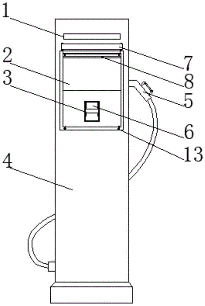
图1为本实用新型的结构示意图;Fig. 1 is the structural representation of the utility model;
图2为本实用新型收纳筒的剖视图;Fig. 2 is the sectional view of the utility model storage cylinder;
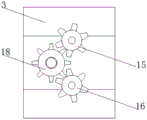
图3为本实用新型固定框的底面结构示意图;3 is a schematic diagram of the bottom surface structure of the fixing frame of the present invention;
图4为本实用新型固定框的侧视剖视图;4 is a side sectional view of the fixing frame of the present invention;
图中:1、指示灯;2、触摸显示屏;3、固定框;4、外护壳体;5、充电枪;6、插卡口;7、收纳筒;8、活动板;9、防护布带;10、滑轮;11、收卷轴;12、回力弹簧;13、卡扣;14、橡胶滚筒;15、第一齿轮;16、第二齿轮;17、清洁滚筒;18、辅助齿轮。In the picture: 1. Indicator light; 2. Touch display screen; 3. Fixed frame; 4. Outer casing; 5. Charging gun; cloth belt; 10, pulley; 11, rewinding shaft; 12, return spring; 13, buckle; 14, rubber roller; 15, first gear; 16, second gear; 17, cleaning roller; 18, auxiliary gear.
具体实施方式Detailed ways
下面将结合本实用新型实施例中的附图,对本实用新型实施例中的技术方案进行清楚、完整地描述,显然,所描述的实施例仅仅是本实用新型一部分实施例,而不是全部的实施例。基于本实用新型中的实施例,本领域普通技术人员在没有做出创造性劳动前提下所获得的所有其他实施例,都属于本实用新型保护的范围。The technical solutions in the embodiments of the present utility model will be clearly and completely described below with reference to the accompanying drawings in the embodiments of the present utility model. Obviously, the described embodiments are only a part of the embodiments of the present utility model, rather than all the implementations. example. Based on the embodiments of the present invention, all other embodiments obtained by those of ordinary skill in the art without creative work fall within the protection scope of the present invention.
请参阅图1-图4,本实用新型提供一种技术方案:一种电动汽车充电站,包括主体,还包括防护机构和辅助清洁机构,主体包括外护壳体4和插卡口6,防护机构包括收纳筒7和活动板8以及卡扣13,收纳筒7位于外护壳体4的内侧,收纳筒7的内侧安装有收卷轴11,收卷轴11的两侧均连接有回力弹簧 12,收卷轴11的外表面连接有防护布带9,防护布带9的端部连接有活动板 8,活动板8的两侧均转动连接有滑轮10,外护壳体4的外表面位于活动板8的下方安装有卡扣13,通过设计安装了位于触摸显示屏2顶部的收纳筒7等,将防护布带9抽出并固定可为触摸显示屏2遮蔽灰尘,增加触摸显示屏2表面的整洁度,可防止触摸显示屏2的表面附着灰尘,且使用和收纳均较为便捷。Please refer to FIG. 1-FIG. 4, the utility model provides a technical solution: an electric vehicle charging station, including a main body, a protection mechanism and an auxiliary cleaning mechanism, the main body includes an outer protective shell 4 and a
为了便于进行磁卡清洁,本实施例中,优选的,辅助清洁机构包括固定框3,固定框3位于插卡口6的内侧,固定框3的内侧安装有橡胶滚筒14,橡胶滚筒14的两侧均连接有第一齿轮15,橡胶滚筒14的下方安装有清洁滚筒17,清洁滚筒17的两侧均连接有第二齿轮16,第一齿轮15和第二齿轮16 之间安装有辅助齿轮18,通过设计安装了位于插卡口6内侧的固定框3等,可在用户插入磁卡充电时,利用插入磁卡的动作可带动橡胶滚筒14和清洁滚筒17转动,在清洁滚筒17转动时可将磁卡具有金属接触面的一面清洁,其过程无需用户做其他多余的操作,一定程度上增加了装置的实用性。In order to facilitate the cleaning of the magnetic card, in this embodiment, preferably, the auxiliary cleaning mechanism includes a
为了便于主体的使用,本实施例中,优选的,主体还包括指示灯1和触摸显示屏2和充电枪5,外护壳体4的前表面连接有触摸显示屏2,触摸显示屏2的底部设置有插卡口6,触摸显示屏2的顶部设置有指示灯1,外护壳体 4的一侧卡合连接有充电枪5。In order to facilitate the use of the main body, in this embodiment, preferably, the main body also includes an indicator light 1 , a touch display screen 2 and a
为了便于活动板8两侧滑轮10可顺着滑槽滑动,本实施例中,优选的,外护壳体4的内侧与活动板8两侧滑轮10对应位置处开设有滑槽,且活动板 8的外表面具有限位凸起。In order to facilitate the sliding of the
为了便于相互联动,本实施例中,优选的,第一齿轮15和第二齿轮16 以及辅助齿轮18之间相互啮合In order to facilitate mutual linkage, in this embodiment, preferably, the
本实用新型的工作原理及使用流程:该装置使用时,将磁卡插入插卡口6 的内侧,在插入过程中,由于橡胶滚筒14与磁卡接触时的摩擦力大,磁卡会带动橡胶滚筒14转动,通过第一齿轮15和第二齿轮16以及辅助齿轮18的相互联动,即可带动清洁滚筒17转动,在清洁滚筒17转动时可将磁卡具有金属接触面的一面清洁;然后在触摸显示屏2上进行相关操作,再将充电枪5 取出并插入电动汽车的充电口内即可进行充电,在充电结束后,将充电枪5 归为,然后向下拨动活动板8,活动板8两侧的滑轮10顺着外护壳体4内侧的滑槽向下滑动,同时可将防护布带9从收纳筒7的内侧抽出,直至活动板8 表面的限位凸起与底部的卡扣13卡合固定,即可将防护布带9固定,此时防护布带9覆盖在触摸显示屏2的表面,可遮蔽灰尘,需要使用装置时,按压两侧的卡扣13,直至卡扣13与限位凸起脱离接触,在回力弹簧12的弹力作用下,即会带动收卷轴11回转,在回转的过程中即可将防护布带9收卷至收纳筒7的内侧,并将活动板8向上提拉,便于触摸显示屏2的使用。The working principle and use process of the utility model: when the device is in use, the magnetic card is inserted into the inner side of the
尽管已经示出和描述了本实用新型的实施例,对于本领域的普通技术人员而言,可以理解在不脱离本实用新型的原理和精神的情况下可以对这些实施例进行多种变化、修改、替换和变型,本实用新型的范围由所附权利要求及其等同物限定。Although the embodiments of the present invention have been shown and described, it will be understood by those skilled in the art that various changes and modifications can be made to these embodiments without departing from the principles and spirit of the present invention , alternatives and modifications, the scope of the present invention is defined by the appended claims and their equivalents.
Claims (4)
Priority Applications (1)
| Application Number | Priority Date | Filing Date | Title |
|---|---|---|---|
| CN201920637696.7U CN209921087U (en) | 2019-05-07 | 2019-05-07 | An electric vehicle charging station |
Applications Claiming Priority (1)
| Application Number | Priority Date | Filing Date | Title |
|---|---|---|---|
| CN201920637696.7U CN209921087U (en) | 2019-05-07 | 2019-05-07 | An electric vehicle charging station |
Publications (1)
| Publication Number | Publication Date |
|---|---|
| CN209921087U true CN209921087U (en) | 2020-01-10 |
Family
ID=69089691
Family Applications (1)
| Application Number | Title | Priority Date | Filing Date |
|---|---|---|---|
| CN201920637696.7U Expired - Fee Related CN209921087U (en) | 2019-05-07 | 2019-05-07 | An electric vehicle charging station |
Country Status (1)
| Country | Link |
|---|---|
| CN (1) | CN209921087U (en) |
Cited By (1)
| Publication number | Priority date | Publication date | Assignee | Title |
|---|---|---|---|---|
| CN111882787A (en) * | 2020-07-23 | 2020-11-03 | 河源市江东新区全程精工制品有限公司 | Shielding protection device for magnetic head of card swiping machine |
-
2019
- 2019-05-07 CN CN201920637696.7U patent/CN209921087U/en not_active Expired - Fee Related
Cited By (1)
| Publication number | Priority date | Publication date | Assignee | Title |
|---|---|---|---|---|
| CN111882787A (en) * | 2020-07-23 | 2020-11-03 | 河源市江东新区全程精工制品有限公司 | Shielding protection device for magnetic head of card swiping machine |
Similar Documents
| Publication | Publication Date | Title |
|---|---|---|
| CN211075575U (en) | Convenient type can fill electric pile from control temperature formula | |
| CN111469696A (en) | Fill electric pile to effectual new energy automobile of charging wire protection | |
| CN118405013A (en) | A liquid-cooled outdoor charging pile | |
| CN107415758B (en) | A portable charging pile with automatic rewinding | |
| CN110451339B (en) | A new energy vehicle charging cable storage device | |
| CN211519311U (en) | Electromagnetic interference resistance shielding structure for automobile charging pile | |
| CN209526751U (en) | A kind of folding screen mobile phone of scratch | |
| CN209096520U (en) | A protection device for embedded charging pile | |
| JP2014236898A (en) | Vacuum cleaner | |
| CN219007623U (en) | Electric vehicle charging pile | |
| CN206814140U (en) | A kind of cable housing case of dust control by ventilation type | |
| CN107482734B (en) | A method of using an automated multifunctional mobile power supply | |
| CN213375668U (en) | Filter cartridge dust removal device | |
| CN211506648U (en) | Self-service photographing terminal | |
| CN203029140U (en) | Winding device for dust collector | |
| CN114913785A (en) | Prevent falling good wearing liquid crystal display module for equipment of nature | |
| CN2584116Y (en) | Vacuum cleaner electric take-up system | |
| CN112455263A (en) | High-power electric automobile charging pile | |
| CN222630753U (en) | A portable vehicle-mounted inverter | |
| CN219583985U (en) | Lifting cover structure of electric bicycle charging pile | |
| CN219715917U (en) | A projector for cable wrapping layer detection | |
| CN220391035U (en) | Charging manager with dustproof function | |
| CN217804370U (en) | Charging gun with wire winding structure | |
| CN223771763U (en) | Fill electric pile cable storage device | |
| CN212151191U (en) | Electric safety cable winding device for construction |
Legal Events
| Date | Code | Title | Description |
|---|---|---|---|
| GR01 | Patent grant | ||
| GR01 | Patent grant | ||
| CB03 | Change of inventor or designer information | ||
| CB03 | Change of inventor or designer information |
Inventor after: Lu Zhigang Inventor after: Zhang Guoyu Inventor before: Lu Zhigang |
|
| CF01 | Termination of patent right due to non-payment of annual fee | ||
| CF01 | Termination of patent right due to non-payment of annual fee |
Granted publication date: 20200110 Termination date: 20210507 |