CN209914532U - High-speed green belt automatic trimmer - Google Patents
High-speed green belt automatic trimmer Download PDFInfo
- Publication number
- CN209914532U CN209914532U CN201822137627.8U CN201822137627U CN209914532U CN 209914532 U CN209914532 U CN 209914532U CN 201822137627 U CN201822137627 U CN 201822137627U CN 209914532 U CN209914532 U CN 209914532U
- Authority
- CN
- China
- Prior art keywords
- vertical
- trimming
- frame
- horizontal
- trimming frame
- Prior art date
- Legal status (The legal status is an assumption and is not a legal conclusion. Google has not performed a legal analysis and makes no representation as to the accuracy of the status listed.)
- Active
Links
Images


Abstract
The utility model discloses a high-speed green belt automatic trimmer in the technical field of agricultural machinery, which comprises a walking device and a trimming mechanism, wherein the trimming mechanism comprises a horizontal trimming knife, the horizontal trimming frame is provided with a conveying mechanism which is used for conveying branches cut by the horizontal trimming knife to the blanking port I and the blanking port II respectively, the blanking port I is communicated with the vertical material cavity I, the blanking port II is communicated with the vertical material cavity II, and the vertical trimming knife I and the vertical trimming knife II are arranged towards the advancing direction of the walking device; the utility model discloses prune neatly, the branch after pruning is recoverable.
Description
Technical Field
The utility model belongs to the technical field of prune machinery, in particular to high-speed greenbelt automatic trimmer.
Background
Green belt, refers to a strip-shaped zone for greening. Can eliminate visual fatigue, purify the environment, beautify the city, reduce traffic accidents and the like, and occupies an irreplaceable important position in the city. Particularly, the high-speed green belt ensures the traffic function of the road, strengthens the functions of water and soil conservation, sight line induction, marking, indication, anti-dazzle, shielding and the like, and can not be illuminated by the headlights of the opposite vehicles when the vehicle runs at high speed at night, thereby being capable of running safely.
The traditional method for pruning the high-speed green belt completely depends on manpower to maintain and prune, and some automatic pruning machines exist at present to prune the high-speed green belt automatically. In the prior art, the patent name of 'an automatic green belt trimmer' with the bulletin number of CN 207978430U with the bulletin date of 20181019 is disclosed, the automatic green belt trimmer comprises a walking device, a vertical lifting device and a trimming device, wherein the trimming device comprises a motor I, a motor II, a motor III, a motor IV, a vertical trimming cutter I, a vertical trimming cutter II, a top trimming cutter I and a top trimming cutter II, the motor I and the motor II are fixed on a trimming cutter fixing frame I and a trimming fixing frame II, the vertical trimming cutter I and the vertical trimming cutter II are respectively fixed on the trimming cutter fixing frame I and the trimming fixing frame II, the motor I is connected with the vertical trimming cutter I through a driving shaft I, the motor II is connected with the vertical trimming cutter II through a driving shaft II, the motor III is connected with the top trimming cutter I through a driving shaft III, the motor III is fixed on the motor fixing frame, the motor IV is connected with the top trimming cutter II through, the motor IV is fixed on a motor fixing frame, the top pruning shear I and the top pruning shear II are respectively fixed on a pruning shear fixing frame III and a pruning fixing frame IV, the driving shaft I, the driving shaft II, the driving shaft III and the driving shaft IV are respectively connected with the pruning shear fixing frame I, the pruning fixing frame II, the pruning fixing frame III and the pruning fixing frame IV through a bearing I and a bearing II, in the technology, a walking device drives a pruning device to walk along the forward direction of a guardrail, the top pruning shear I and the top pruning shear II are arranged downwards, when the walking device prunes a green belt while walking, the green belt at the top cannot be pruned neatly, the vertical pruning shear I and the vertical pruning shear II are arranged towards the direction of the green belt, the vertical pruning shear I and the vertical pruning shear II synchronously rotate to prune the upper part of the green belt, and simultaneously the vertical pruning shear I and the vertical pruning shear II move forwards, the pruning machine can not prune in some places and is not tidy, in addition, the pruned branches directly fall on the ground and are difficult to clean when being blown to the expressway, the cleaning work is unsafe, the workload is increased, and the cost is high.
SUMMERY OF THE UTILITY MODEL
An object of the utility model is to overcome the weak point among the prior art, provide a high-speed greenbelt automatic trimming machine, solved and pruned uneven technological problem among the prior art, the utility model discloses prune neatly, branch after pruning can not fall subaerially, reduces work load, reduce cost.
The purpose of the utility model is realized like this: a high-speed automatic green belt trimmer comprises a walking device and a trimming mechanism, wherein the trimming mechanism comprises a horizontal trimming knife, a first vertical trimming knife and a second vertical trimming knife, the walking device is connected with a first horizontal trimming frame in a lifting and rotating manner, the lower side of the horizontal trimming frame is provided with a first vertical trimming frame and a second vertical trimming frame which are arranged at intervals, the lower side of the horizontal trimming frame is provided with a first blanking port and a second blanking port, the first vertical trimming frame is provided with a first vertical material cavity, the second vertical trimming frame is provided with a second vertical material cavity, the horizontal trimming knife is arranged at the front side of the horizontal trimming frame, the horizontal trimming frame is provided with a conveying mechanism for conveying branches trimmed by the horizontal trimming knife to the first blanking port and the second blanking port respectively, the first blanking port is communicated with the first vertical material cavity, the second blanking port is communicated with the second vertical material cavity, and the first vertical trimming knife is vertically arranged at the inward side of the first vertical trimming frame in the left-right direction, the vertical pruning knife II is vertically arranged on the inward side of the vertical pruning frame II, and the vertical pruning knife I and the vertical pruning knife II are both arranged towards the advancing direction of the walking device.
The horizontal pruning knife, the vertical pruning knife I and the vertical pruning knife II in the utility model are respectively the pruning parts of three electric pruners or electric hedge trimmers, and the parts except the pruning parts are fixed on the horizontal pruning frame; before the green belts are trimmed, the walking device walks, the horizontal trimming frame is arranged in front of the walking device, when the horizontal trimming frame is close to the green belts, the horizontal trimming frame is controlled to rotate, the horizontal trimming frame is made to rotate to the side edge of the walking device, the horizontal trimming frame is lifted, the bottom sides of the first vertical trimming frame and the second vertical trimming frame are higher than the guard rail, when the horizontal trimming frame is arranged right above the nearest green belts, the horizontal trimming frame is controlled to descend, and when the horizontal trimming frame descends to a set distance, the horizontal trimming knife is ensured to be in contact with the upper parts of the green belts; the utility model discloses during operation, horizontal pruning sword prunes the top of greenbelt, and the left and right sides of vertical pruning sword two pairs greenbelt is pruned to vertical pruning sword one and vertical pruning sword, and the branch that the horizontal pruning sword was pruned is carried backward through conveying mechanism, and the branch that cuts falls into respectively along blanking mouth one and blanking mouth two in vertical material chamber one and vertical material chamber two, and running gear continues the walking, and vertical pruning sword one and vertical pruning sword two directly enter vertical material chamber one and vertical material chamber two respectively with the branch that the greenbelt left and right sides was pruned, realize the recovery of branch; the utility model realizes the pruning of rectangular green belts through the arrangement of the horizontal pruning knife, the vertical pruning knife I and the vertical pruning knife II, so that the green belts are more tidy, and branches pruned enter the vertical material cavity I and the vertical material cavity II, thereby realizing the recovery of the pruned branches; can be applied to the work of pruning rectangular greenbelts.
In order to convey branches cut by the horizontal trimming knife into the horizontal trimming frame, one end of the horizontal trimming frame is a feed inlet, and the other end of the horizontal trimming frame is closed, the conveying mechanism comprises two rotating discs which are rotatably connected onto the horizontal trimming frame, a plurality of shifting pieces are distributed on inward sides of the two rotating discs, the shifting pieces rotate around the rotating center of the rotating discs, and when the shifting pieces rotate, outward sides of at least one shifting piece are always in front of the horizontal trimming knife; a screw shaft is rotatably connected to the horizontal trimming frame behind the horizontal trimming knife, a first spiral blade and a second spiral blade which are opposite in rotation direction are respectively connected to the screw shaft in the direction from the center to the outside in the length direction, the first spiral blade extends towards the first blanking port, and the second spiral blade extends towards the second blanking port; in the design, the poking sheet pokes branches cut by the horizontal trimming knife into the feeding hole, the rotation direction of the spiral shaft is controlled, so that the branches poked into the horizontal trimming frame are conveyed from the middle part to the left end and the right end and fall from the first blanking port and the second blanking port respectively, the branches falling from the first blanking port enter the first vertical material cavity, and the branches falling from the second blanking port enter the second vertical material cavity.
In order to more smoothly recover the cut branches, the lower part of the first vertical trimming frame is rotatably connected with a first crushing cutter shaft, at least one first crushing movable cutter is arranged on the first crushing cutter shaft, a plurality of first crushing fixed cutters are arranged on the first vertical trimming frame corresponding to the bottom side of the first vertical material cavity, and one first crushing movable cutter is arranged between the two first crushing fixed cutters in the length direction; the lower part of the vertical trimming frame II is rotatably connected with a crushing cutter shaft II, at least one crushing movable cutter II is arranged on the crushing cutter shaft II, a plurality of crushing fixed cutters II are arranged on the vertical trimming frame II corresponding to the bottom side of the vertical material cavity II, and one crushing movable cutter II is arranged between the two crushing fixed cutters II in the length direction; in the design, the first crushing cutter shaft and the second crushing cutter shaft rotate at a high speed, the first crushing movable cutter and the first crushing fixed cutter further crush the branches falling in the first vertical material cavity, and the second crushing fixed cutter further crush the branches falling in the second vertical material cavity, so that crushed branch scraps are easier to recycle.
In order to further improve the reliability of branch recovery work, a first fixed supporting baffle is arranged on the front side of the first vertical trimming frame, the first fixed supporting baffle is far away from the first vertical trimming knife, a first conveying belt is rotatably connected to the lower portion of the first fixed supporting baffle, a first friction tooth protruding upwards is arranged on the first conveying belt, the upper side of the first friction tooth is not lower than the bottom side of the first vertical material cavity, and branches falling onto the first conveying belt are conveyed into the first vertical material cavity by the first conveying belt; a second fixed supporting baffle is arranged on the front side of the second vertical trimming frame and far away from the second vertical trimming knife, a second conveying belt is rotatably connected to the lower portion of the second fixed supporting baffle, a second friction tooth protruding upwards is arranged on the second conveying belt, the upper side of the second friction tooth is not lower than the bottom side of the second vertical material cavity, and branches falling onto the second conveying belt are conveyed into the second vertical material cavity by the second conveying belt; in the design, the branches falling from the first blanking port are conveyed into the first vertical cavity through the first conveying belt, the branches falling from the second blanking port are conveyed into the second vertical cavity through the second conveying belt, and the friction teeth increase the friction force between the branches and the conveying belts to prevent the branches from being blown to the ground.
In order to realize the discharge of branch scraps, a first discharge port communicated with the external environment is formed in a first vertical trimming frame behind the first crushing cutter shaft, a second discharge port communicated with the external environment is formed in a second vertical trimming frame behind the second crushing cutter shaft, the bottom side of the first discharge port is not higher than that of the first crushing cutter shaft, and the bottom side of the second discharge port is not higher than that of the second crushing cutter shaft.
In order to realize the recovery of branch scraps, a centrifugal fan and a collecting device are arranged on the walking device, an air suction inlet of the centrifugal fan is connected with a first air suction pipe and a second air suction pipe, one end, away from the centrifugal fan, of the first air suction pipe is connected with a vertical trimming frame, the first air suction pipe is communicated with a discharge hole, one end, away from the centrifugal fan, of the second air suction pipe is connected with a vertical trimming frame, and the second air suction pipe is communicated with the discharge hole; the centrifugal fan discharges the discharged branch scraps to a collecting device; in the design, the centrifugal fan sucks branch scraps in the vertical material cavity I into the centrifugal fan along the discharge port I and the suction pipe in sequence, the centrifugal fan sucks branch scraps in the vertical material cavity II into the centrifugal fan along the discharge port II and the suction pipe II in sequence, and the centrifugal fan discharges the sucked branch scraps into the collecting device for collection.
In order to further improve the reliability of branch recovery, a first guide plate inclining towards the direction of the first conveying belt is arranged on the inner side of the first vertical trimming frame, and the first guide plate is arranged in the first vertical material cavity; a second material guide plate which is inclined towards the direction of the second conveying belt is arranged on the inner side of the second vertical trimming frame and is arranged in the second vertical material cavity; in the design, the first guide plate conveys the branches falling from the first blanking port to the first conveying belt, the second guide plate conveys the branches falling from the second blanking port to the second conveying belt, the first conveying belt conveys the branches to the first crushing movable cutter and the second crushing fixed cutter, and the second conveying belt conveys the branches to the second crushing movable cutter and the second crushing fixed cutter, so that the falling branches are all crushed, and the branch scraps formed after crushing are sucked away and collected more easily.
In order to realize the rotation and the lifting of the horizontal trimming frame, the front side of the walking device is fixedly connected with a supporting seat, a rotating plate is rotatably connected onto the supporting seat, a fixing sleeve is fixedly arranged on the upper side of the rotating plate, a lifting rod is slidably arranged in the fixing sleeve, the upper side of the lifting rod is hinged with one end of a supporting frame, the other end of the supporting frame is hinged with a connecting frame, and the horizontal trimming frame is fixed on the lower side of the connecting frame.
In order to realize the adjustment of the levelness of the horizontal trimming frame, a first linear driver is hinged to the outer side of the lifting rod, a first telescopic rod capable of doing reciprocating linear motion is connected to the first linear driver, and the first telescopic rod is hinged to the supporting frame; the support frame is far away from that the one end at lifter place articulates there is linear actuator two, is connected with the telescopic link two that can do reciprocating linear motion on the linear actuator two, telescopic link two is articulated with the upper portion of link, and telescopic link two is in the top of support frame and link articulated department.
Drawings
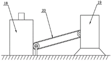
Fig. 1 is a front view of the present invention.
Fig. 2 is a partially enlarged view of a portion a in fig. 1.
Fig. 3 is a first perspective view of the present invention.
Fig. 4 is a partially enlarged view of fig. 2 at B.
Fig. 5 is a first three-dimensional structure diagram of the trimming mechanism of the present invention.
Fig. 6 is a second perspective view of the trimming mechanism of the present invention.
Fig. 7 is a partial enlarged view at C in fig. 6.
Fig. 8 is a three-dimensional structure diagram of the middle trimming mechanism of the present invention.
Fig. 9 is a partial enlarged view of fig. 8 at D.
Fig. 10 is a second perspective view of the present invention.
Fig. 11 is a partial enlarged view at E in fig. 2.
Fig. 12 is a schematic view of the connection structure of the cyclone separator and the packaging machine of the present invention.
Wherein, 1, the trimming mechanism comprises a first conveyor belt 101, a first crushing fixed cutter 102, a first driving motor 103, a first crushing cutter shaft 104, a first crushing motor 105, a first crushing movable cutter 106, a first vertical trimming frame 107, a first 108 material guide plate 108, a first 109 material outlet, a first fixed supporting baffle 110, a first 111 vertical material cavity, a second 112 driving motor 112, a second 113 conveyor belt 114, a second 114 material outlet, a second 115 vertical material cavity, a second 116 material guide plate 117, a second 117 crushing motor 118, a first 119 helical blade, a helical shaft 120, a shifting blade 121, a driving rotating shaft 122, a rotating disc 123, a first 124 vertical trimming cutter 124, a first 125 friction tooth, a first 126 driving wheel, a first 127 driven wheel 128 conveying motor, a shifting motor 129, a second 130 friction tooth, a second 131 driven wheel, a second 132 driving wheel, a second 133 vertical trimming frame 133, a second 134 vertical trimming cutter 135, a second crushing movable cutter 136, a second fixed supporting baffle 136, a horizontal trimming frame 137 and a second crushing fixed cutter, 139 crushing cutter shaft II, 140 horizontal trimming cutter, 2 linear driver I, 3 fixed sleeve, 4 supporting seat, 5 hydraulic station, 6 walking device, 7 lifting rod, 8 supporting frame, 9 linear driver II, 10 connecting frame, 11 electric cabinet, 12 hydraulic motor, 13 rotating plate, 14 transmission gear, 15 rotating shaft, 16 driven gear, 17 centrifugal fan, 18 cyclone separator, 19 packing machine, 20 conveying device, 21 driving device, 22 blanking port I and 23 blanking port II.
Detailed Description
The present invention will be further explained with reference to the accompanying drawings.
The automatic pruning machine for the high-speed green belts as shown in fig. 1 ~ 12 comprises a walking device 6 and a pruning mechanism 1, wherein the pruning mechanism 1 comprises a horizontal pruning knife 140, a first vertical pruning knife 124 and a second vertical pruning knife 134, the walking device 6 is connected with the horizontal pruning frame 137 in a lifting and rotating manner, the lower side of the horizontal pruning frame 137 is provided with a first vertical pruning frame 107 and a second vertical pruning frame 133 which are arranged at intervals, the first vertical pruning frame 107 is arranged at the left side of the horizontal pruning frame 137, the second vertical pruning frame 133 is arranged at the right side of the horizontal pruning frame 137, the lower side of the horizontal pruning frame 137 is provided with a first cutting port 22 and a second cutting port 23, the first vertical pruning frame 107 is provided with a first vertical cutting cavity 111, the second vertical pruning frame 133 is provided with a second vertical cutting cavity 115, the horizontal pruning frame 140 is arranged at the front side of the horizontal pruning frame 137, the horizontal pruning frame 137 is provided with a conveying mechanism for conveying branches cut by the horizontal pruning knife 140 to the first cutting port 22 and the second cutting port 23 respectively conveying the two cutting blade shafts 120 which are arranged at the first horizontal cutting knife 137, the horizontal cutting knife 140 and the two cutting knife 137, the two cutting knife 140, the horizontal cutting knife 140 is connected with the horizontal cutting knife 140, the two cutting knife shaft 120, the two cutting blade conveying shafts 120, the horizontal cutting shaft 120, the two cutting shaft 120 is arranged at the horizontal cutting frame 120, the two cutting knife 140 is connected with the horizontal cutting shaft 120, the horizontal cutting frame 120 is connected with the vertical cutting shaft 120, the horizontal cutting frame, the two cutting shaft 120 is connected with the horizontal cutting shaft 120, the two cutting shaft 120, the horizontal cutting shaft 120, the two cutting frame, the two cutting shaft 140, the two cutting shaft 120 is connected with the vertical cutting shaft 140, the horizontal cutting shaft 120 is connected with the horizontal cutting shaft 120, the horizontal cutting shaft 135, the horizontal cutting shaft 120, the two cutting shaft 120, the horizontal cutting shaft 120, the two cutting shaft 135, the two cutting shaft 120 is connected with the horizontal cutting shaft 135, the vertical cutting shaft 135, the two cutting shaft 135, the horizontal cutting shaft 135, the two cutting shaft 135, the cutting shaft 135 is connected with the two cutting shaft 135, the two cutting shaft 135 is connected with the two cutting shaft 135, the cutting shaft 135 is connected with the two cutting shaft 135, the two cutting shaft 135 is connected with the cutting shaft 135, the two cutting shaft 135, the.
In order to further improve the reliability of branch recovery work, a first fixed supporting baffle 110 is arranged on the front side of a first vertical trimming frame 107, the first fixed supporting baffle 110 and the first vertical supporting baffle are integrated, in the left-right direction, the first fixed supporting baffle 110 is far away from a first vertical trimming knife 124, a first driving motor 103 is fixedly connected to the lower portion of the first fixed supporting baffle 110, a first driving wheel 126 is rotatably connected to the first driving motor 103, the first driving wheel 126 is in transmission connection with a first driven wheel 127 through a first conveying belt 101, a first upwardly-protruding friction tooth 125 is arranged on the first conveying belt 101, the upper side of the first friction tooth 125 is not lower than the bottom side of the first vertical material cavity 111, and branches falling onto the first conveying belt 101 are conveyed into the first vertical material cavity 111 by the first conveying; the front side of the second vertical trimming frame 133 is provided with a second fixed supporting baffle 136, the second fixed connecting frame 10 and the second vertical trimming frame 133 are integrated, in the left-right direction, the second fixed supporting baffle 136 is far away from the second vertical trimming blade 134, the lower part of the second fixed supporting baffle 136 is fixedly connected with a second driving motor 112, the second driving motor 112 is rotatably connected with a second driving wheel 132, the second driving wheel 132 is in transmission connection with a second driven wheel 131 through a second conveying belt 113, the second conveying belt 113 is provided with a second upwardly-protruding friction tooth 130, the upper side of the second friction tooth 130 is not lower than the bottom side of the second vertical material cavity 115, and branches falling onto the second conveying belt 113 are conveyed into the second vertical material cavity 115 by the second conveying belt 113.
In order to realize the discharge of branch scraps, a first discharge port 109 communicated with the external environment is formed in a first vertical trimming frame 107 behind a first crushing cutter shaft 104, a second discharge port 114 communicated with the external environment is formed in a second vertical trimming frame 133 behind a second crushing cutter shaft 139, the bottom side of the first discharge port 109 is not higher than the bottom side of the first crushing cutter shaft 104, and the bottom side of the second discharge port 114 is not higher than the bottom side of the second crushing cutter shaft 139; in order to realize the recovery of the branch scraps, a centrifugal fan 17 and a collecting device are arranged on the walking device 6, an air suction inlet of the centrifugal fan 17 is connected with a first air suction pipe and a second air suction pipe, one end of the first air suction pipe, far away from the centrifugal fan 17, is connected with a first vertical trimming frame 107, the first air suction pipe is communicated with a first discharge hole 109, one end of the second air suction pipe, far away from the centrifugal fan 17, is connected with a second vertical trimming frame 133, the second air suction pipe is communicated with a second discharge hole 114 (one end of the first air suction pipe is connected with the first vertical trimming frame 107, the other end of the first air suction pipe is connected with one end of a three-way pipe, one end of the second air suction pipe is connected with the second vertical trimming frame 133, the other two ends of the three-way pipe are respectively connected with the other end of the second air suction pipe and an air suction inlet of the centrifugal fan 17, (the connection, described herein for ease of understanding); the centrifugal fan 17 discharges the discharged branch scraps to the collecting device, the collecting device comprises a cyclone separator 18 and a packing machine 19, the centrifugal fan 17 is connected with the cyclone separator 18 through a pipeline, the cyclone separator 18 discharges gas, the branch scraps are output from the discharge end of the cyclone separator 18, the output branch scraps enter the packing machine 19 through a conveying device 20 to be compressed and packed, and the branch scraps are recovered; a first material guide plate 108 inclined towards the direction of the first conveying belt 101 is arranged on the inner side of the first vertical trimming frame 107, and the first material guide plate 108 is arranged in a first vertical material cavity 111; the second guide plate 116 inclined towards the second conveyor belt 113 is arranged on the inner side of the second vertical trimming frame 133, and the second guide plate 116 is arranged in the second vertical material cavity 115.
In order to realize the rotation and lifting of the horizontal trimming frame 137, the front side of the walking device 6 is fixedly connected with a supporting seat 4, a hydraulic station 5 is arranged on the supporting seat 4, a rotating plate 13 is rotatably connected on the supporting seat 4, a hydraulic motor 12 is arranged on the lower side of the supporting seat 4, a transmission gear 14 is connected on the hydraulic motor 12 in a transmission way, a rotating shaft 15 is rotatably connected on the supporting seat 4, a driven gear 16 is meshed on the transmission gear 14, the driven gear 16 is connected with the rotating shaft 15, the transmission gear 14 is an external gear, the driven gear 16 is an internal gear, the rotating shaft 15 is connected with the rotating plate 13, a fixed sleeve 3 is fixedly arranged on the upper side of the rotating plate 13, a driving device 21 is arranged in the fixed sleeve 3, the driving device 21 is preferably a hydraulic cylinder, a lifting rod 7 is slidably arranged in the fixed sleeve 3, the, in fig. 1 of the present application, only the structural diagram of the connection between the hydraulic cylinder and the lifting rod 7 is shown, and no further description is needed), the upper side of the lifting rod 7 is hinged to one end of the supporting frame 8, the other end of the supporting frame 8 is hinged to the connecting frame 10, and the horizontal trimming frame 137 is fixed to the lower side of the connecting frame 10; the outer side of the lifting rod 7 is hinged with a first linear driver 2, the first linear driver 2 is connected with a first telescopic rod capable of doing reciprocating linear motion, and the first telescopic rod is hinged with a support frame 8; one end of the support frame 8, far away from the lifting rod 7, is hinged with a second linear driver 9, the second linear driver 9 is connected with a second telescopic rod capable of doing reciprocating linear motion, the second telescopic rod is hinged with the upper part of the connecting frame 10, and the second telescopic rod is arranged above the hinged part of the support frame 8 and the connecting frame 10; in this embodiment, the first linear actuator 2 and the second linear actuator 9 are preferably hydraulic cylinders, and the hydraulic station 5 is controlled by a control system on the support base 4 to control the actions of the hydraulic cylinders.
The horizontal trimming blade 140, the vertical trimming blade one 124 and the vertical trimming blade two 134 in the present invention are trimming portions of three electric pruners or electric hedge trimmers (for convenience of description, referred to as electric trimmers herein), respectively, and portions other than the trimming portions are fixed on the horizontal trimming frame 137; in addition, a controller is arranged in a cab of the traveling device 6, an electric cabinet 11 is arranged on the upper side of the rotating plate 13, the controller sends a control signal to the electric cabinet 11, the electric cabinet 11 controls the actions of the hydraulic motor 12 and each hydraulic cylinder through the hydraulic station 5, and the electric cabinet 11 also controls the actions of the electric trimmer, the toggle motor 129, the conveying motor 128, the first driving motor 103, the second driving motor 112, the first crushing motor 105 and the second crushing motor 117; before the green belt is trimmed, the walking device 6 walks, the horizontal trimming frame 137 is controlled to rotate in front of the walking device 6 when approaching the green belt, the horizontal trimming frame 137 is rotated to the side edge of the walking device 6, the horizontal trimming frame 137 is lifted, the bottom sides of the first vertical trimming frame 107 and the second vertical trimming frame 133 are higher than the guard rail, when the horizontal trimming frame 137 is positioned right above the nearest green belt, the horizontal trimming frame 137 is controlled to descend, and when the horizontal trimming frame 137 descends to a set distance, the horizontal trimming knife 140 is ensured to be in contact with the upper part of the green belt; controlling the action of the first linear driver 2 and the second linear driver 9 to enable the horizontal trimming blade 140 to be horizontal, enabling the first vertical trimming blade 124 and the second vertical trimming blade 134 to be in a vertical state, and stopping the action of the first linear driver 2 and the second linear driver 9; when the utility model works, the toggle motor 129, the first conveying motor 128, the second conveying motor 128, the first grinding motor 105, the second grinding motor 117, the centrifugal fan 17, the cyclone separator 18 and the packing machine 19 are started to act, the horizontal pruning knife 140 prunes the top of the green belt, the first vertical pruning knife 124 and the second vertical pruning knife 134 prune the left side and the right side of the green belt, the toggle motor 129 drives the driving shaft 122 to rotate, the driving shaft 122 drives the rotating disc 123 to rotate, the rotating disc 123 rotates to drive the shifting sheet 121 to rotate, the action direction of the toggle motor 129 is controlled to enable the shifting sheet 121 to rotate forwards, the shifting sheet 121 shifts branches pruned by the horizontal pruning knife 140 into the horizontal pruning frame 137, branches entering the horizontal pruning frame 137 are respectively conveyed to the first material opening 22 and the second material opening 23 through the first spiral blade 119 and the second spiral blade 118, branches fall into the first vertical material cavity 111 and the second material cavity 115 respectively along the first material opening 22 and the second material opening 23, the branches sliding down along the first material guide plate 108 fall on the first conveying belt 101, the branches sliding down along the second material guide plate 116 fall on the second conveying belt 113, the walking device 6 continuously walks, the branches trimmed at the left and right sides of the green belt by the first vertical trimming cutter 124 and the second vertical trimming cutter 134 fall on the first conveying belt 101 and the second conveying belt 113 respectively, the action directions of the first driving motor 103 and the second driving motor 112 are controlled, the branches are conveyed backwards by the first conveying belt 101 and the second conveying belt 113, the branches conveyed into the first vertical material cavity 111 are crushed under the action of the first crushing movable cutter 106 and the first crushing fixed cutter 102, the branches conveyed into the second vertical material cavity 115 are crushed under the action of the second crushing movable cutter 135 and the second crushing fixed cutter 138, the crushed branches are sucked away by the centrifugal fan 17 through the first air suction pipe and the second air suction pipe, the sucked branches are conveyed into the cyclone separator 18 by the centrifugal fan 17, the cyclone separator 18 discharges gas and branch scraps, and the discharged branch scraps are conveyed to a packing machine 19 through a conveying device 20 to be compressed and packed, so that the complete recovery of the branch scraps is realized; the utility model discloses before work, the pruning mechanism 1 is in the place ahead of running gear 6, do not influence the travel of other vehicles, when needing to prune, pruning mechanism 1 rotates to the greenbelt place one end, lift pruning mechanism 1 makes pruning reliable the going on, the levelness of horizontal pruning sword 140 is adjustable, when pruning, horizontal pruning sword 140 level, vertical pruning sword 124 and vertical pruning sword two 134 are vertical, make the greenbelt more neat, the branch that prunes down gets into vertical material chamber one 111 and vertical material chamber two 115 under the effect of conveyer belt one 101 and conveyer belt two 113, the branch that gets into vertical material chamber one 111 and vertical material chamber two 115 smashes through smashing cutter one 106 and smashing fixed knife one 102, the branch bits after smashing are siphoned away, realize the recovery of branch bits, the branch after pruning can not fall to subaerial, reduce work load, reduce cost; can be applied to the work of pruning rectangular greenbelts.
The present invention is not limited to the above embodiments, and based on the technical solutions disclosed in the present invention, those skilled in the art can make some replacements and transformations for some technical features without creative labor according to the disclosed technical contents, and these replacements and transformations are all within the protection scope of the present invention.
Claims (7)
1. A high-speed green belt automatic trimmer comprises a walking device and is characterized by further comprising a trimming mechanism, wherein the trimming mechanism comprises a horizontal trimming cutter, a first vertical trimming cutter and a second vertical trimming cutter, a supporting seat is fixedly connected to the front side of the walking device, a hydraulic motor is arranged on the lower side of the supporting seat, a transmission gear is connected to the hydraulic motor in a transmission mode, a rotating shaft is rotatably connected to the supporting seat, a rotating plate is connected to the rotating shaft, a driven gear is meshed with the transmission gear and is connected with the rotating shaft, the transmission gear is an outer gear and is an inner gear, a fixing sleeve is fixedly arranged on the upper side of the rotating plate, a lifting rod is slidably arranged in the fixing sleeve, the upper side of the lifting rod is hinged to one end of a supporting frame, the other end of the supporting frame is hinged to a, the first linear driver is connected with a first telescopic rod capable of doing reciprocating linear motion, and the first telescopic rod is hinged with the support frame; the end, far away from the lifting rod, of the support frame is hinged with a linear actuator II, the linear actuator II is connected with a telescopic rod II capable of doing reciprocating linear motion, the telescopic rod II is hinged with the upper portion of the connecting frame, the telescopic rod II is arranged above the hinged portion of the support frame and the connecting frame, a horizontal trimming frame is fixedly connected to the lower side of the connecting frame, a vertical trimming frame I and a vertical trimming frame II are arranged at intervals on the lower side of the horizontal trimming frame, a blanking port I and a blanking port II are formed in the lower side of the horizontal trimming frame, a vertical material cavity I is formed in the vertical trimming frame I, a vertical material cavity II is formed in the vertical trimming frame II, the horizontal trimming knife is arranged on the front side of the horizontal trimming frame, a conveying mechanism for conveying branches cut by the horizontal trimming knife to the blanking port I and the blanking port II is arranged on the horizontal trimming frame, the blanking port I is communicated with the vertical material cavity I, and the blanking port, in the left-right direction, the first vertical trimming cutter is vertically arranged on the inward side of the first vertical trimming frame, the second vertical trimming cutter is vertically arranged on the inward side of the second vertical trimming frame, and the first vertical trimming cutter and the second vertical trimming cutter are both arranged towards the advancing direction of the walking device.
2. The automatic high-speed green belt trimmer according to claim 1, wherein one end of the horizontal trimming frame is provided with the feeding hole, the other end of the horizontal trimming frame is closed, the conveying mechanism comprises two rotating discs which are rotatably connected to the horizontal trimming frame, a plurality of shifting sheets are arranged on inward sides of the two rotating discs, the shifting sheets rotate around the rotating center of the rotating discs, and when the shifting sheets rotate, the outward side of at least one shifting sheet is always in front of the horizontal trimming blade; the horizontal trimming frame behind the horizontal trimming knife is rotatably connected with a screw shaft, the center of the screw shaft in the length direction is connected with a first spiral blade and a second spiral blade which are opposite in rotation direction outwards, the first spiral blade extends towards the first blanking port, and the second spiral blade extends towards the second blanking port.
3. The automatic high-speed green belt trimmer according to claim 1, wherein the lower part of the first vertical trimming frame is rotatably connected with a first crushing cutter shaft, the first crushing cutter shaft is provided with at least one first crushing movable cutter, a plurality of first crushing fixed cutters are arranged on the corresponding first vertical trimming frame at the bottom side of the first vertical material cavity, and one first crushing movable cutter is arranged between two first crushing fixed cutters in the length direction; the lower part of the vertical trimming frame II is rotatably connected with a crushing cutter shaft II, at least one crushing movable cutter II is arranged on the crushing cutter shaft II, a plurality of crushing fixed cutters II are arranged on the vertical trimming frame II corresponding to the bottom side of the vertical material cavity II, and one crushing movable cutter II is arranged between the two crushing fixed cutters II in the length direction.
4. The automatic high-speed green belt trimmer according to claim 1, wherein a first fixed supporting baffle is arranged on the front side of the first vertical trimming frame, the first fixed supporting baffle is far away from the first vertical trimming knife, a first conveying belt is rotatably connected to the lower portion of the first fixed supporting baffle, a first friction tooth protruding upwards is arranged on the first conveying belt, the upper side of the first friction tooth is not lower than the bottom side of the first vertical material cavity, and branches falling onto the first conveying belt are conveyed into the first vertical material cavity by the first conveying belt; the front side of the second vertical trimming frame is provided with a second fixed supporting baffle, the second fixed supporting baffle is far away from the second vertical trimming knife, the lower part of the second fixed supporting baffle is rotatably connected with a second conveying belt, the second conveying belt is provided with a second friction tooth protruding upwards, the upper side of the second friction tooth is not lower than the bottom side of the second vertical material cavity, and branches falling onto the second conveying belt are conveyed into the second vertical material cavity by the second conveying belt.
5. The automatic high-speed green belt trimmer according to claim 3, wherein the first vertical trimming frame behind the first crushing cutter shaft is provided with a first discharge port communicated with the external environment, the second vertical trimming frame behind the second crushing cutter shaft is provided with a second discharge port communicated with the external environment, the bottom side of the first discharge port is not higher than the bottom side of the first crushing cutter shaft, and the bottom side of the second discharge port is not higher than the bottom side of the second crushing cutter shaft.
6. The automatic high-speed green belt trimmer according to claim 5, wherein the walking device is provided with a centrifugal fan and a collecting device, an air suction inlet of the centrifugal fan is connected with a first air suction pipe and a second air suction pipe, one end of the first air suction pipe, which is far away from the centrifugal fan, is connected with the vertical trimming frame, the first air suction pipe is communicated with the first discharge hole, one end of the second air suction pipe, which is far away from the centrifugal fan, is connected with the vertical trimming frame, and the second air suction pipe is communicated with the second discharge hole; the centrifugal fan discharges the discharged branch scraps to the collecting device.
7. The automatic high-speed trimming machine for green belts as claimed in claim 4, wherein the inner side of the first vertical trimming frame is provided with a first material guiding plate which is inclined towards the direction of the first conveying belt, and the first material guiding plate is arranged in the first vertical material cavity; and a second material guide plate which is inclined towards the direction of the second conveying belt is arranged on the inner side of the second vertical trimming frame and is arranged in the second vertical material cavity.
Priority Applications (1)
| Application Number | Priority Date | Filing Date | Title |
|---|---|---|---|
| CN201822137627.8U CN209914532U (en) | 2018-12-19 | 2018-12-19 | High-speed green belt automatic trimmer |
Applications Claiming Priority (1)
| Application Number | Priority Date | Filing Date | Title |
|---|---|---|---|
| CN201822137627.8U CN209914532U (en) | 2018-12-19 | 2018-12-19 | High-speed green belt automatic trimmer |
Publications (1)
| Publication Number | Publication Date |
|---|---|
| CN209914532U true CN209914532U (en) | 2020-01-10 |
Family
ID=69064628
Family Applications (1)
| Application Number | Title | Priority Date | Filing Date |
|---|---|---|---|
| CN201822137627.8U Active CN209914532U (en) | 2018-12-19 | 2018-12-19 | High-speed green belt automatic trimmer |
Country Status (1)
| Country | Link |
|---|---|
| CN (1) | CN209914532U (en) |
Cited By (2)
| Publication number | Priority date | Publication date | Assignee | Title |
|---|---|---|---|---|
| CN111758412A (en) * | 2020-07-14 | 2020-10-13 | 嘉兴市茂景园林有限公司 | Multi-functional greenbelt trimming means of unified standard |
| CN112772179A (en) * | 2021-01-12 | 2021-05-11 | 南京奔卓网络科技有限公司 | Highway road both sides brush forest trimming means |
-
2018
- 2018-12-19 CN CN201822137627.8U patent/CN209914532U/en active Active
Cited By (2)
| Publication number | Priority date | Publication date | Assignee | Title |
|---|---|---|---|---|
| CN111758412A (en) * | 2020-07-14 | 2020-10-13 | 嘉兴市茂景园林有限公司 | Multi-functional greenbelt trimming means of unified standard |
| CN112772179A (en) * | 2021-01-12 | 2021-05-11 | 南京奔卓网络科技有限公司 | Highway road both sides brush forest trimming means |
Similar Documents
| Publication | Publication Date | Title |
|---|---|---|
| CN111480470A (en) | Municipal afforestation secondary-cleaning-free green plant trimming equipment and implementation mode | |
| CN109452020A (en) | A kind of clipping device for trimming rectangle greenbelt | |
| CN209914532U (en) | High-speed green belt automatic trimmer | |
| CN209914530U (en) | Pruning machine for pruning rectangular green belts | |
| CN209914531U (en) | Pruning device for pruning rectangular green belt | |
| CN108738655B (en) | Reciprocating cutting type rose pruning and field returning machine | |
| CN207505509U (en) | Plant root system shearing mechanism | |
| CN207885208U (en) | A kind of sugar-cane cutting machine | |
| CN209609294U (en) | Point band rectangle pruning mechanism in a kind of highway | |
| CN109429763A (en) | A kind of cutter | |
| CN210275171U (en) | Self-propelled straw pick-up feed bundling machine | |
| CN209949938U (en) | Cutting device for stubble cutting machine | |
| CN2810141Y (en) | Garlic whisker and peduncle cutting machine | |
| CN106134629A (en) | Automatization's Folium Allii tuberosi harvester | |
| CN206559843U (en) | A kind of hand propelled cornstalk harvesting device | |
| CN106688429A (en) | Sea-buckthorn branch harvesting and smashing integrated device | |
| CN204929753U (en) | A kind of pruning head of green belt along highway pruning car | |
| CN109452022A (en) | It is a kind of for trimming the trimmer of rectangle greenbelt | |
| CN108401704B (en) | Wheel-track combined rose pruning machine | |
| CN109452021A (en) | A kind of high speed automatic trimmer for green belts | |
| CN110786164B (en) | Multifunctional trimming machine | |
| CN216218825U (en) | Leek flower and leek harvester | |
| CN108748310A (en) | A kind of meat cubelets cutting machine | |
| CN204598756U (en) | A kind of tea plant trimming machine | |
| CN108739082A (en) | Agaricus bisporus mushroom bed is with cutting mushroom vehicle |
Legal Events
| Date | Code | Title | Description |
|---|---|---|---|
| GR01 | Patent grant | ||
| GR01 | Patent grant |