CN209903214U - Horizontal joint mechanical arm for feeding and discharging materials in numerical control machining center and lathe - Google Patents
Horizontal joint mechanical arm for feeding and discharging materials in numerical control machining center and lathe Download PDFInfo
- Publication number
- CN209903214U CN209903214U CN201920707368.XU CN201920707368U CN209903214U CN 209903214 U CN209903214 U CN 209903214U CN 201920707368 U CN201920707368 U CN 201920707368U CN 209903214 U CN209903214 U CN 209903214U
- Authority
- CN
- China
- Prior art keywords
- arm
- motor
- unloading
- seat
- machining center
- Prior art date
- Legal status (The legal status is an assumption and is not a legal conclusion. Google has not performed a legal analysis and makes no representation as to the accuracy of the status listed.)
- Active
Links
Images


Landscapes
- Manipulator (AREA)
Abstract
本实用新型涉及机械技术领域,具体为数控加工中心和车床上下料的水平关节机械臂,包括机械臂主体,机械臂主体由底臂、中臂、外臂以及气动手指组成,机械臂主体安装在机床门口的外侧边缘处。该数控加工中心和车床上下料的水平关节机械臂,通过设置的z轴电机、第一电机、第二电机、第三电机以及通过活塞杆的活塞运动带动一对夹指做夹取动作,使气动手指能空间内做x、y、z轴的自由运动并可夹放工件,从而达到工件的夹取和放置目的,该数控加工中心和车床上下料的水平关节机械臂,体型较小,较传统机械臂最大化节省空间,给机床调试人员的调试工作带来方便。
This utility model relates to the field of mechanical technology, specifically a horizontal articulated robotic arm for loading and unloading CNC machining centers and lathes. It includes a main body composed of a base arm, a middle arm, an outer arm, and pneumatic fingers. The main body is installed at the outer edge of the machine tool door. This horizontal articulated robotic arm for loading and unloading CNC machining centers and lathes uses a Z-axis motor, a first motor, a second motor, a third motor, and a piston rod to drive a pair of gripping fingers to perform gripping actions. This allows the pneumatic fingers to move freely along the x, y, and z axes in space and to grip and place workpieces, thus achieving the purpose of workpiece gripping and placement. This horizontal articulated robotic arm for loading and unloading CNC machining centers and lathes is relatively small, maximizing space saving compared to traditional robotic arms and facilitating the debugging work of machine tool operators.
Description
技术领域technical field
本实用新型涉及机械技术领域,具体为数控加工中心和车床上下料的水平关节机械臂。The utility model relates to the technical field of machinery, in particular to a numerical control machining center and a horizontal joint mechanical arm for unloading materials on a lathe.
背景技术Background technique
机械臂是一个多输入多输出、高度非线性、强耦合的复杂系统。因其独特的操作灵活性,已在工业装配、安全防爆等领域得到广泛应用,在数控加工中心和车床的批量生产加工中,稳定性高、安全性高、错误率少的机械臂逐渐替代传统的人工劳作。由于传统的机械臂应用到数控加工中心和车床时需要占据机床门口处的大片地方,给机床调试人员的调试工作带来不便,鉴于此,我们提出数控加工中心和车床上下料的水平关节机械臂。The robotic arm is a complex system with multiple inputs and multiple outputs, highly nonlinear and strong coupling. Due to its unique operational flexibility, it has been widely used in industrial assembly, safety and explosion-proof and other fields. In the mass production and processing of CNC machining centers and lathes, robotic arms with high stability, high safety and low error rate gradually replace traditional ones. people work. Since the traditional robotic arm needs to occupy a large area at the door of the machine tool when it is applied to the CNC machining center and lathe, it brings inconvenience to the debugging work of the machine tool debugging personnel. In view of this, we propose a horizontal joint robotic arm for unloading and unloading on the CNC machining center and the lathe. .
实用新型内容Utility model content
本实用新型的目的在于提供数控加工中心和车床上下料的水平关节机械臂,以解决上述背景技术中提出的传统的机械臂应用到数控加工中心和车床时需要占据机床门口处的大片地方,给机床调试人员的调试工作带来不便的问题。The purpose of the utility model is to provide a horizontal joint mechanical arm for loading and unloading on a numerical control machining center and a lathe, so as to solve the problem that the traditional mechanical arm proposed in the above-mentioned background technology needs to occupy a large area at the door of the machine tool when applied to the numerical control machining center and the lathe. The debugging work of the machine tool debugging personnel brings inconvenience.
为实现上述目的,本实用新型提供如下技术方案:To achieve the above object, the utility model provides the following technical solutions:
数控加工中心和车床上下料的水平关节机械臂,包括机械臂主体,所述机械臂主体由底臂、中臂、外臂以及气动手指组成,所述底臂的内部从上往下依次设置有z轴电机、与所述z轴电机同轴连接的滚珠丝杆、安装在所述滚珠丝杆上并与所述滚珠丝杆螺纹连接的运动块以及安装在所述底臂内部底端位置处的第一电机,所述底臂外部的底端位置处安装有第一减速器,所述底臂的侧端安装有一对线轨,所述中臂的一端安装有固定板,所述固定板的侧端安装有若干个与所述线轨滑动连接的线轨滑块,所述中臂的顶端并排安装有第二电机和第三电机,所述中臂另一端的底部位置处安装有受所述第二电机带动的第二减速器,所述外臂的一端安装在所述第二减速器的输出端,所述外臂的另一端底部位置处安装有受所述第三电机带动的第三减速器,所述气动手指安装在所述第三减速器的输出端;The horizontal joint mechanical arm for unloading and unloading of CNC machining centers and lathes includes a main body of the mechanical arm. The main body of the mechanical arm is composed of a bottom arm, a middle arm, an outer arm and a pneumatic finger. The inside of the bottom arm is sequentially provided with A z-axis motor, a ball screw coaxially connected to the z-axis motor, a moving block mounted on the ball screw and threadedly connected to the ball screw, and a bottom end position inside the bottom arm The first motor, a first reducer is installed at the bottom end position outside the bottom arm, a pair of line rails are installed on the side end of the bottom arm, and one end of the middle arm is installed with a fixing plate, the fixing plate A number of line rail sliders slidingly connected to the line rail are installed on the side end of the middle arm, a second motor and a third motor are installed side by side at the top of the middle arm, and a receiving device is installed at the bottom position of the other end of the middle arm. The second reducer driven by the second motor, one end of the outer arm is installed at the output end of the second reducer, and the other end of the outer arm is installed at the bottom position of the second reducer driven by the third motor. a third reducer, the pneumatic finger is installed at the output end of the third reducer;
所述机械臂主体安装在机床门口的外侧边缘处,所述机床的外侧安装有用于放置工件的放置板,所述机床门口的外侧边缘处安装有竖板,所述竖板的顶底两端分别设有顶凸座和底凸座,所述底臂安装在所述顶凸座与所述底凸座之间。The main body of the mechanical arm is installed at the outer edge of the door of the machine tool, a placement plate for placing workpieces is installed on the outer side of the machine tool, a vertical plate is installed at the outer edge of the door of the machine tool, and the top and bottom ends of the vertical plate are installed. A top boss and a bottom boss are respectively provided, and the bottom arm is installed between the top boss and the bottom boss.
优选的,所述底臂的顶端通过螺栓安装有旋转支撑座,所述顶凸座上紧密焊接有转轴,转轴伸入所述旋转支撑座中,所述第一减速器的输出端通过螺栓与所述底凸座固定连接。Preferably, a rotating support seat is installed on the top end of the bottom arm through bolts, a rotating shaft is tightly welded on the top boss seat, the rotating shaft extends into the rotating support seat, and the output end of the first reducer is connected to the rotating support seat through bolts. The bottom boss is fixedly connected.
优选的,所述z轴电机的输出轴末端与所述滚珠丝杆的顶端通过联轴器相连接,所述滚珠丝杆的顶底两端均设有丝杆底座,所述滚珠丝杆与所述丝杆底座转动连接。Preferably, the end of the output shaft of the z-axis motor is connected with the top end of the ball screw through a coupling, the top and bottom ends of the ball screw are provided with screw bases, and the ball screw is connected to the The screw base is rotatably connected.
优选的,所述运动块的中部位置处通过螺栓固定有丝杆螺母,所述丝杆螺母的中部位置处呈螺纹孔状,螺纹孔与所述滚珠丝杆上的螺纹形状相匹配,所述运动块的侧端通过螺栓固定有固定杆,所述固定杆的末端插入到所述固定板中。Preferably, a screw nut is fixed at the middle position of the moving block by bolts, the middle position of the screw nut is in the shape of a threaded hole, and the threaded hole matches the shape of the thread on the ball screw, the The side end of the moving block is fixed with a fixing rod by bolts, and the end of the fixing rod is inserted into the fixing plate.
优选的,所述第二电机的输出轴末端以及所述第二减速器的输入端均安装有第一同步带轮,两个所述第一同步带轮之间通过同步皮带相连接。Preferably, both the end of the output shaft of the second motor and the input end of the second reducer are equipped with a first synchronous pulley, and the two first synchronous pulleys are connected by a synchronous belt.
优选的,所述第二减速器的中部套接有空心结构的同步转轴,所述同步转轴的内部套接有信号线保护管,所述第三电机的输出轴末端、所述同步转轴的顶底两端以及所述第三减速器的输入端均安装有第二同步带轮,位于所述中臂以及所述外臂内的两对所述第二同步带轮之间分别通过同步皮带相连接。Preferably, a synchronous rotating shaft with a hollow structure is sleeved in the middle of the second reducer, a signal line protection tube is sleeved inside the synchronous rotating shaft, the end of the output shaft of the third motor, and the top of the synchronous rotating shaft are sleeved. Both the bottom ends and the input end of the third reducer are equipped with second synchronous pulleys, and the two pairs of the second synchronous pulleys located in the middle arm and the outer arm are respectively connected to each other through a synchronous belt. connect.
优选的,所述气动手指包括通过螺栓固定在所述第三减速器输出端的顶座、伸入所述顶座内的活塞杆以及与所述顶座滑动连接的一对夹指。Preferably, the pneumatic fingers include a top seat fixed on the output end of the third reducer by bolts, a piston rod extending into the top seat, and a pair of clamping fingers slidably connected with the top seat.
优选的,所述顶座的顶端开设有空腔,所述顶座的侧端面处开设有与所述空腔底部相连通的底气孔,所述空腔口部边缘处搭接有密封圈,所述密封圈的一角处弯曲有凹口,所述空腔的顶端通过螺栓安装有顶盖,所述顶盖的顶端边缘处开设有与所述凹口处相连通的顶气孔。Preferably, the top of the top seat is provided with a cavity, the side end surface of the top seat is provided with a bottom air hole communicating with the bottom of the cavity, and a sealing ring is overlapped at the edge of the mouth of the cavity. A notch is bent at a corner of the sealing ring, a top cover is installed on the top of the cavity through bolts, and a top air hole communicated with the notch is opened at the top edge of the top cover.
优选的,所述活塞杆的顶端通过螺栓安装有与所述空腔尺寸相匹配的活塞,所述活塞杆的底端通过螺栓安装有导向块。Preferably, the top end of the piston rod is installed with a piston matching the size of the cavity through bolts, and the bottom end of the piston rod is installed with a guide block through bolts.
优选的,所述夹指的顶端设有导向座,所述顶座的底部开设有用于安装所述导向座的导向槽,所述导向槽的内壁呈齿状结构,所述导向座的外壁与所述导向槽相咬合,所述导向座顶部的拐角处开设有与所述导向块外形尺寸相匹配的斜槽,所述夹指通过所述斜槽与所述导向块滑动连接。Preferably, the top end of the clip finger is provided with a guide seat, the bottom of the top seat is provided with a guide groove for installing the guide seat, the inner wall of the guide groove is in a tooth-like structure, and the outer wall of the guide seat is in the shape of a tooth. The guide grooves are engaged with each other, and the corner of the top of the guide seat is provided with an oblique groove matching the outer dimension of the guide block, and the clip finger is slidably connected to the guide block through the oblique groove.
与现有技术相比,本实用新型的有益效果是:Compared with the prior art, the beneficial effects of the present utility model are:
1.该数控加工中心和车床上下料的水平关节机械臂,通过设置的第一电机带动底臂在机床外转动、z轴电机带动中臂做竖直方向的运动、第二电机带动外臂转动、第三电机带动气动手指转动以及活塞杆的活塞运动带动一对夹指做夹取动作,使气动手指能空间内做x、y、z轴的自由运动,从而达到工件的夹取和放置目的;1. The CNC machining center and the horizontal joint mechanical arm for loading and unloading on the lathe are driven by the first motor to drive the bottom arm to rotate outside the machine tool, the z-axis motor drives the middle arm to move in the vertical direction, and the second motor drives the outer arm to rotate , The third motor drives the pneumatic fingers to rotate and the piston movement of the piston rod drives a pair of clamping fingers to do the clamping action, so that the pneumatic fingers can freely move the x, y and z axes in the space, so as to achieve the purpose of clamping and placing the workpiece ;
2.该数控加工中心和车床上下料的水平关节机械臂,体型较小,较传统机械臂最大化节省空间,解决了传统的机械臂应用到数控加工中心和车床时需要占据机床门口处的大片地方,给机床调试人员的调试工作带来不便的问题。2. The CNC machining center and the horizontal joint robotic arm for loading and unloading on the lathe are smaller in size, which maximizes space saving compared with the traditional robotic arm, which solves the problem that the traditional robotic arm needs to occupy a large area at the door of the machine tool when it is applied to the CNC machining center and lathe. This will bring inconvenience to the debugging work of the machine tool debugging personnel.
附图说明Description of drawings
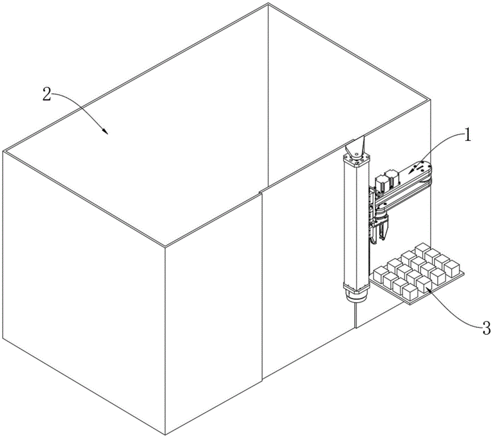
图1为本实用新型的整体结构示意图;Fig. 1 is the overall structure schematic diagram of the present utility model;
图2为本实用新型中机械臂主体的安装示意图;Fig. 2 is the installation schematic diagram of the main body of the manipulator in the utility model;
图3为本实用新型的底臂结构示意图;Fig. 3 is the bottom arm structure schematic diagram of the present utility model;
图4为本实用新型的中臂安装示意图;Fig. 4 is the middle arm installation schematic diagram of the present invention;
图5为本实用新型中第二电机与第二减速器的传动示意图;Fig. 5 is the transmission schematic diagram of the second motor and the second reducer in the utility model;
图6为本实用新型中第三电机与第三减速器的传动示意图;Fig. 6 is the transmission schematic diagram of the third motor and the third reducer in the utility model;
图7为本实用新型的气动手指结构示意图;7 is a schematic structural diagram of a pneumatic finger of the present invention;
图8为本实用新型中顶座的结构示意图;Fig. 8 is the structural representation of the top seat in the utility model;
图9为本实用新型中顶座的顶部结构示意图。FIG. 9 is a schematic view of the top structure of the top seat in the present invention.
图中:1、机械臂主体;11、底臂;111、旋转支撑座;112、z轴电机;1121、联轴器;113、滚珠丝杆;1131、丝杆底座;114、运动块;1141、丝杆螺母;1142、固定杆;115、第一电机;116、第一减速器;17、线轨;12、中臂;121、固定板;1211、线轨滑块;122、第二电机;123、第三电机;124、第二减速器;125、第一同步带轮;126、同步转轴;1261、信号线保护管;127、第二同步带轮;13、外臂;131、第三减速器;14、气动手指;141、顶座;1411、空腔;1412、底气孔;1413、密封圈;1414、凹口;1415、顶盖;1416、顶气孔;1417、导向槽;142、活塞杆;1421、活塞;1422、导向块;143、夹指;1431、导向座;1432、斜槽;2、机床;21、放置板;22、竖板;221、顶凸座;222、底凸座;3、工件。In the figure: 1. Robot arm body; 11. Bottom arm; 111. Rotation support base; 112, Z-axis motor; 1121, Coupling; 113, Ball screw; 1131, Screw base; 114, Movement block; , screw nut; 1142, fixed rod; 115, first motor; 116, first reducer; 17, line rail; 12, middle arm; 121, fixing plate; 1211, line rail slider; 122, second motor ; 123, the third motor; 124, the second reducer; 125, the first synchronous pulley; 126, the synchronous shaft; 1261, the signal line protection tube; 127, the second synchronous pulley; 13, the outer arm; 131, the first Three reducers; 14, pneumatic finger; 141, top seat; 1411, cavity; 1412, bottom air hole; 1413, sealing ring; 1414, notch; 1415, top cover; 1416, top air hole; 1417, guide groove; 142 , piston rod; 1421, piston; 1422, guide block; 143, clip finger; 1431, guide seat; 1432, chute; 2, machine tool; 21, placing plate; 22, vertical plate; 221, top boss; 222, Bottom boss; 3. Workpiece.
具体实施方式Detailed ways
下面将结合本实用新型实施例中的附图,对本实用新型实施例中的技术方案进行清楚、完整地描述,显然,所描述的实施例仅仅是本实用新型一部分实施例,而不是全部的实施例。基于本实用新型中的实施例,本领域普通技术人员在没有做出创造性劳动前提下所获得的所有其他实施例,都属于本实用新型保护的范围。The technical solutions in the embodiments of the present utility model will be clearly and completely described below with reference to the accompanying drawings in the embodiments of the present utility model. Obviously, the described embodiments are only a part of the embodiments of the present utility model, rather than all the implementations. example. Based on the embodiments of the present invention, all other embodiments obtained by those of ordinary skill in the art without creative work fall within the protection scope of the present invention.
在本实用新型的描述中,需要理解的是,术语“中心”、“纵向”、“横向”、“长度”、“宽度”、“厚度”、“上”、“下”、“前”、“后”、“左”、“右”、“竖直”、“水平”、“顶”、“底”、“内”、“外”、“顺时针”、“逆时针”等指示的方位或位置关系为基于附图所示的方位或位置关系,仅是为了便于描述本实用新型和简化描述,而不是指示或暗示所指的设备或元件必须具有特定的方位、以特定的方位构造和操作,因此不能理解为对本实用新型的限制。In the description of the present invention, it should be understood that the terms "center", "longitudinal", "lateral", "length", "width", "thickness", "upper", "lower", "front", "Back", "Left", "Right", "Vertical", "Horizontal", "Top", "Bottom", "Inner", "Outer", "Clockwise", "Counterclockwise" etc. Or the positional relationship is based on the orientation or positional relationship shown in the accompanying drawings, which is only for the convenience of describing the present invention and simplifying the description, rather than indicating or implying that the referred device or element must have a specific orientation, be constructed in a specific orientation and operation, so it cannot be construed as a limitation to the present invention.
此外,术语“第一”、“第二”、“第三”仅用于描述目的,而不能理解为指示或暗示相对重要性或者隐含指明所指示的技术特征的数量。由此,限定有“第一”、“第二”、“第三”的特征可以明示或者隐含地包括一个或者更多个该特征。在本实用新型的描述中,“若干”的含义是至少两个,例如两个,三个等,除非另有明确具体的限定。Furthermore, the terms "first", "second" and "third" are used for descriptive purposes only, and should not be construed as indicating or implying relative importance or implying the number of indicated technical features. Thus, a feature defined as "first", "second", "third" may expressly or implicitly include one or more of that feature. In the description of the present invention, "a number of" means at least two, such as two, three, etc., unless otherwise expressly and specifically defined.
请参阅图1-9,本实用新型提供一种技术方案:Please refer to Fig. 1-9, the utility model provides a technical solution:
数控加工中心和车床上下料的水平关节机械臂,包括机械臂主体1,机械臂主体1由底臂11、中臂12、外臂13以及气动手指14组成,底臂11的内部从上往下依次设置有z轴电机112、与z轴电机112同轴连接的滚珠丝杆113、安装在滚珠丝杆113上并与滚珠丝杆113螺纹连接的运动块114以及安装在底臂11内部底端位置处的第一电机115,底臂11外部的底端位置处安装有第一减速器116,底臂11的侧端安装有一对线轨17,中臂12的一端安装有固定板121,固定板121的侧端安装有若干个与线轨17滑动连接的线轨滑块1211,中臂12的顶端通过螺栓并排安装有第二电机122和第三电机123,中臂12另一端的底部位置处安装有受第二电机122带动的第二减速器124,外臂13的一端通过螺栓安装在第二减速器124的输出端,外臂13的另一端底部位置处安装有受第三电机123带动的第三减速器131,气动手指14安装在第三减速器131的输出端;The horizontal joint manipulator arm of CNC machining center and lathe, including manipulator main body 1, the manipulator main body 1 consists of a
机械臂主体1安装在机床2门口的外侧边缘处,机床2的外侧通过螺栓安装有用于放置工件3的放置板21,机床2门口的外侧边缘处通过螺栓安装有竖板22,竖板22的顶底两端分别设有顶凸座221和底凸座222,竖板22、顶凸座221以及底凸座222为一体成型结构,底臂11安装在顶凸座221与底凸座222之间。The main body 1 of the robot arm is installed at the outer edge of the door of the
本实施例中,底臂11的顶端通过螺栓安装有旋转支撑座111,顶凸座221上紧密焊接有转轴,转轴伸入旋转支撑座111中,第一电机115通过螺栓与底臂11固定连接,第一电机115的输出轴末端通过螺栓与第一减速器116的输入端固定连接,第一减速器116的输出端通过螺栓与底凸座222固定连接,使第一电机115与外界电源相接通时,第一电机115开始工作并带动第一减速器116的输入端转动,由于第一减速器116的输出端固定在底凸座222上,因此随着第一电机115的工作,在第一减速器116的减速下第一减速器116带动底臂11整体被在底凸座222与顶凸座221之间进行转动。In this embodiment, the top end of the
具体的,z轴电机112的输出轴末端与滚珠丝杆113的顶端通过联轴器1121相连接,滚珠丝杆113的顶底两端均设有丝杆底座1131,滚珠丝杆113与丝杆底座1131转动连接,z轴电机112通过螺栓安装在箱体的顶端,箱体通过螺栓安装在底臂11内,位于顶端的丝杆底座1131通过螺栓固定在箱体的底端,位于底端的丝杆底座1131通过螺栓固定在固定座上,固定座通过螺栓固定在位于滚珠丝杆113底端位置处的底臂11内,联轴器1121位于箱体内,当z轴电机112与外界电源相接通时,z轴电机112通过联轴器1121带动滚珠丝杆113转动。Specifically, the end of the output shaft of the z-axis motor 112 is connected with the top end of the ball screw 113 through a coupling 1121 , and the top and bottom ends of the ball screw 113 are provided with a screw base 1131 . The ball screw 113 and the screw The base 1131 is rotatably connected, the z-axis motor 112 is installed on the top of the box by bolts, the box is installed in the
进一步的,运动块114的中部位置处通过螺栓固定有丝杆螺母1141,丝杆螺母1141的中部位置处呈螺纹孔状,螺纹孔与滚珠丝杆113上的螺纹形状相匹配,使得滚珠丝杆113的转动能在螺纹的作用下转化为运动块114沿滚珠丝杆113做出的竖直方向上的运动,运动块114的侧端通过螺栓固定有固定杆1142,固定杆1142的末端插入到固定板121中,使得运动块114在运动的同时能够对中臂12进行拨动。Further, a screw nut 1141 is fixed at the middle position of the moving block 114 by bolts, and the middle position of the screw nut 1141 is in the shape of a threaded hole, and the threaded hole matches the shape of the thread on the ball screw 113, so that the ball screw The rotation of 113 can be converted into the vertical movement of the moving block 114 along the ball screw 113 under the action of the thread. In the fixing
进一步的,第二电机122的输出轴末端以及第二减速器124的输入端均安装有第一同步带轮125,两个第一同步带轮125之间通过同步皮带相连接,当第二电机122与外界电源相接通时,第二电机122开始工作并带动第一同步带轮125转动并在同步皮带的传动下通过另一个第一同步带轮125带动第二减速器124的输入端转动,在第二减速器124的减速下,第二减速器124的输出端带动外臂13转动。Further, the end of the output shaft of the
需要补充的是,第二减速器124的中部套接有空心结构的同步转轴126,同步转轴126的内部套接有对信号线进行保护的信号线保护管1261,第三电机123的输出轴末端、同步转轴126的顶底两端以及第三减速器131的输入端均安装有第二同步带轮127,位于中臂12以及外臂13内的两对第二同步带轮127之间分别通过同步皮带相连接,将第三电机123与外界电源相接通时,第三电机123开始工作并通过中臂12内的同步皮带在第二同步带轮127的作用下带动同步转轴126转动,同时随着同步转轴126的转动,同步转轴126通过第二同步带轮127在同步皮带的作用下带动第三减速器131的输入端转动。It should be added that the middle of the
此外,气动手指14包括通过螺栓固定在第三减速器131输出端的顶座141、伸入顶座141内的活塞杆142以及与顶座141滑动连接的一对夹指143,顶座141的顶端开设有空腔1411,顶座141的侧端面处开设有与空腔1411底部相连通的底气孔1412,使气体能通过底气孔1412进入到空腔1411内,空腔1411口部边缘处搭接有密封圈1413,密封圈1413的一角处弯曲有凹口1414,空腔1411的顶端通过螺栓安装有顶盖1415,顶盖1415的顶端边缘处开设有与凹口1414处相连通的顶气孔1416,使气体能通过顶气孔1416经过凹口1414处进入到空腔1411内。In addition, the
进一步的,活塞杆142的顶端通过螺栓安装有与空腔1411尺寸相匹配的活塞1421,活塞1421位于底气孔1412与顶气孔1416之间,底气孔1412与顶气孔1416的孔口处均连接有气管,通过气管向空腔1411内通气从而在气压的作用下带动活塞1421在空腔1411内做活塞运动,活塞杆142的底端通过螺栓安装有导向块1422,随着活塞1421做活塞运动,活塞1421通过活塞杆142带动导向块1422做运动。Further, the top end of the
具体的,夹指143的顶端设有导向座1431,顶座141的底部开设有用于安装导向座1431的导向槽1417,导向槽1417的内壁呈齿状结构,导向座1431的外壁与导向槽1417相咬合,导向座1431顶部的拐角处开设有与导向块1422外形尺寸相匹配的斜槽1432,夹指143通过斜槽1432与导向块1422滑动连接,当活塞1421通过活塞杆142带动导向块1422向上做运动时,夹指143在斜槽1432的斜面作用下拉动两个夹指143沿导向槽1417互相靠近,从而达到夹紧工件3的目的,当活塞1421通过活塞杆142带动导向块1422向下运动时夹指143在斜槽1432的斜面作用下推动两个夹指143沿导向槽1417互相远离,从而达到松开工件3的目的。Specifically, the top of the
值得说明的是,本实用新型体型较小,较传统机械臂最大化节省空间,本实用新型中涉及到的z轴电机112、第一电机115、第二电机122以及第三电机123均为现有技术,第一减速器116、第二减速器124以及第三减速器131均使用现有技术中的中空谐波减速机,本领域技术人员完全可以实现,无需赘言,本实用新型不涉及电子电路的改进。It is worth noting that the utility model is smaller in size, and saves space compared to the traditional mechanical arm. The z-axis motor 112, the first motor 115, the
本实用新型的数控加工中心和车床上下料的水平关节机械臂在使用时,通过将第一电机115与外界电源相接通时,第一电机115开始工作并带动第一减速器116的输入端转动,由于第一减速器116的输出端固定在底凸座222上,因此随着第一电机115的工作,在第一减速器116的减速下第一减速器116带动底臂11整体被在底凸座222与顶凸座221之间进行转动,通过将第二电机122与外界电源相接通时,第二电机122开始工作并在同步皮带的传动下通过第一同步带轮125带动第二减速器124的输入端转动,从而使第二减速器124的输出端带动外臂13转动,通过将第三电机123与外界电源相接通时,第三电机123开始工作并通过中臂12内的同步皮带在第二同步带轮127的作用下带动同步转轴126转动,同时随着同步转轴126的转动,同步转轴126通过第二同步带轮127在同步皮带的作用下带动第三减速器131的输入端转动,从而使气动手指14进行转动,在接着通过气管向空腔1411内通气从而在气压的作用下带动活塞1421在空腔1411内做活塞运动,活塞杆142的底端通过螺栓安装有导向块1422,随着活塞1421做活塞运动,活塞1421通过活塞杆142带动导向块1422做运动,当活塞1421通过活塞杆142带动导向块1422向上做运动时,夹指143在斜槽1432的斜面作用下拉动两个夹指143沿导向槽1417互相靠近,从而达到夹紧工件3的目的,当活塞1421通过活塞杆142带动导向块1422向下运动时夹指143在斜槽1432的斜面作用下推动两个夹指143沿导向槽1417互相远离,从而达到松开工件3的目的,最后当z轴电机112与外界电源相接通时,z轴电机112通过联轴器1121带动滚珠丝杆113转动从而使得运动块114在运动的同时能够对中臂12进行拨动,使得机械臂主体1垂直的z方向由丝杆和线轨传动,水平的x与y方向由中臂12以及外臂13完成,工件的夹取与松开由气动手指14完成,且机械臂主体1整体结构较小,最大化节省了空间。When the numerical control machining center and the horizontal joint mechanical arm for unloading and unloading on the lathe of the present invention are in use, when the first motor 115 is connected to the external power supply, the first motor 115 starts to work and drives the input end of the first reducer 116 Rotation, since the output end of the first reducer 116 is fixed on the
以上显示和描述了本实用新型的基本原理、主要特征和本实用新型的优点。本行业的技术人员应该了解,本实用新型不受上述实施例的限制,上述实施例和说明书中描述的仅为本实用新型的优选例,并不用来限制本实用新型,在不脱离本实用新型精神和范围的前提下,本实用新型还会有各种变化和改进,这些变化和改进都落入要求保护的本实用新型范围内。本实用新型要求保护范围由所附的权利要求书及其等效物界定。The basic principles, main features and advantages of the present invention have been shown and described above. Those skilled in the art should understand that the present invention is not limited by the above-mentioned embodiments. The above-mentioned embodiments and descriptions are only preferred examples of the present invention and are not intended to limit the present invention. Under the premise of the spirit and scope, the present invention will have various changes and improvements, and these changes and improvements all fall within the scope of the claimed invention. The claimed scope of the present invention is defined by the appended claims and their equivalents.
Claims (10)
Priority Applications (1)
| Application Number | Priority Date | Filing Date | Title |
|---|---|---|---|
| CN201920707368.XU CN209903214U (en) | 2019-05-17 | 2019-05-17 | Horizontal joint mechanical arm for feeding and discharging materials in numerical control machining center and lathe |
Applications Claiming Priority (1)
| Application Number | Priority Date | Filing Date | Title |
|---|---|---|---|
| CN201920707368.XU CN209903214U (en) | 2019-05-17 | 2019-05-17 | Horizontal joint mechanical arm for feeding and discharging materials in numerical control machining center and lathe |
Publications (1)
| Publication Number | Publication Date |
|---|---|
| CN209903214U true CN209903214U (en) | 2020-01-07 |
Family
ID=69048213
Family Applications (1)
| Application Number | Title | Priority Date | Filing Date |
|---|---|---|---|
| CN201920707368.XU Active CN209903214U (en) | 2019-05-17 | 2019-05-17 | Horizontal joint mechanical arm for feeding and discharging materials in numerical control machining center and lathe |
Country Status (1)
| Country | Link |
|---|---|
| CN (1) | CN209903214U (en) |
Cited By (2)
| Publication number | Priority date | Publication date | Assignee | Title |
|---|---|---|---|---|
| CN111764598A (en) * | 2020-07-07 | 2020-10-13 | 徐子桐 | A kind of wooden door installation construction method |
| CN116276264A (en) * | 2023-04-07 | 2023-06-23 | 浙江博民机电股份有限公司 | The loading and unloading mechanism of the waterwheel type special machine |
-
2019
- 2019-05-17 CN CN201920707368.XU patent/CN209903214U/en active Active
Cited By (4)
| Publication number | Priority date | Publication date | Assignee | Title |
|---|---|---|---|---|
| CN111764598A (en) * | 2020-07-07 | 2020-10-13 | 徐子桐 | A kind of wooden door installation construction method |
| CN111764598B (en) * | 2020-07-07 | 2021-12-10 | 莆田晟熙贸易有限公司 | A kind of wooden door installation construction method |
| CN116276264A (en) * | 2023-04-07 | 2023-06-23 | 浙江博民机电股份有限公司 | The loading and unloading mechanism of the waterwheel type special machine |
| CN116276264B (en) * | 2023-04-07 | 2026-04-07 | 浙江博民机电股份有限公司 | Loading and unloading mechanism of waterwheel-type special machine |
Similar Documents
| Publication | Publication Date | Title |
|---|---|---|
| CN104924061B (en) | Horizontal joint lock screw manipulator and adopt full-automatic production line of this manipulator | |
| CN213499255U (en) | Industrial robot composite clamp | |
| CN205111421U (en) | Arm robot | |
| CN108869521A (en) | A kind of fixed device of vacuum chuck | |
| CN205166950U (en) | A plug-in execution terminal of a manipulator with two heads and a large rotation angle | |
| CN205766158U (en) | A high-precision five-axis manipulator | |
| CN105127981A (en) | Three-freedom-degree transfer robot with movable support | |
| CN204322094U (en) | A kind of industrial robot pneumatic gripping device | |
| CN111003500A (en) | Automobile engine part truss robot loading and unloading and carrying system | |
| CN216882892U (en) | Truss manipulator | |
| CN214604363U (en) | A new type of truss robot with high flexibility | |
| CN106426255A (en) | Clamping claw | |
| CN212683993U (en) | Practical mechanical arm | |
| CN206049175U (en) | Built-in glass carving four-axis manipulator | |
| CN209385480U (en) | A kind of fixed device of vacuum chuck | |
| CN210312449U (en) | Multi freedom material loading manipulator device | |
| CN112356062A (en) | Clamping device for industrial robot | |
| CN209831628U (en) | Human-robot Collaborative Robot | |
| CN207840821U (en) | One kind tightening feeding device | |
| CN214213082U (en) | Multifunctional truss manipulator paw | |
| CN216229470U (en) | Device is got with robot clamp to intelligent manufacturing | |
| CN212197481U (en) | a transport device | |
| CN206263960U (en) | Flexible manipulator structure | |
| CN211729231U (en) | Electrode paw | |
| CN210910076U (en) | Three-jaw robot end effector |
Legal Events
| Date | Code | Title | Description |
|---|---|---|---|
| GR01 | Patent grant | ||
| GR01 | Patent grant | ||
| CP01 | Change in the name or title of a patent holder | ||
| CP01 | Change in the name or title of a patent holder |
Address after: 325000 East of First Floor, 89 Kuocang West Road, Longwan District, Wenzhou City, Zhejiang Province Patentee after: Wenzhou RIKANG Machinery Technology Factory Address before: 325000 East of First Floor, 89 Kuocang West Road, Longwan District, Wenzhou City, Zhejiang Province Patentee before: WENZHOU RIKANG SMOKING SET FACTORY |
|
| CP03 | Change of name, title or address | ||
| CP03 | Change of name, title or address |
Address after: 325000 Zhejiang Province, Wenzhou City, Longwan District, Yaoxi Street, Nanyang Avenue 2999, Tianxin Tiansi Digital Economy Industry Center, Building C1-2, Room 101 Patentee after: Wenzhou Rikang Machinery Technology Co.,Ltd. Country or region after: China Address before: 325000 East of First Floor, 89 Kuocang West Road, Longwan District, Wenzhou City, Zhejiang Province Patentee before: Wenzhou RIKANG Machinery Technology Factory Country or region before: China |