CN209902921U - Quick and stable cutting device of pre-buried pipe - Google Patents
Quick and stable cutting device of pre-buried pipe Download PDFInfo
- Publication number
- CN209902921U CN209902921U CN201920431126.2U CN201920431126U CN209902921U CN 209902921 U CN209902921 U CN 209902921U CN 201920431126 U CN201920431126 U CN 201920431126U CN 209902921 U CN209902921 U CN 209902921U
- Authority
- CN
- China
- Prior art keywords
- fixed
- plate
- motor
- shell
- buried pipe
- Prior art date
- Legal status (The legal status is an assumption and is not a legal conclusion. Google has not performed a legal analysis and makes no representation as to the accuracy of the status listed.)
- Expired - Fee Related
Links
- 238000005520 cutting process Methods 0.000 title claims abstract description 42
- 230000006835 compression Effects 0.000 claims abstract description 22
- 238000007906 compression Methods 0.000 claims abstract description 22
- 239000000428 dust Substances 0.000 claims abstract description 22
- 229920000742 Cotton Polymers 0.000 claims abstract description 19
- 239000011491 glass wool Substances 0.000 claims abstract description 16
- 238000009423 ventilation Methods 0.000 claims abstract description 9
- 238000009434 installation Methods 0.000 claims abstract description 8
- 230000009467 reduction Effects 0.000 claims abstract description 6
- 238000005498 polishing Methods 0.000 claims description 14
- 239000011521 glass Substances 0.000 claims 2
- 238000010521 absorption reaction Methods 0.000 claims 1
- 244000309464 bull Species 0.000 claims 1
- 230000000694 effects Effects 0.000 abstract description 6
- 230000009286 beneficial effect Effects 0.000 abstract description 3
- 239000011257 shell material Substances 0.000 description 10
- 238000004519 manufacturing process Methods 0.000 description 6
- 230000008878 coupling Effects 0.000 description 5
- 238000010168 coupling process Methods 0.000 description 5
- 238000005859 coupling reaction Methods 0.000 description 5
- 238000010586 diagram Methods 0.000 description 5
- 229910000831 Steel Inorganic materials 0.000 description 2
- 239000010959 steel Substances 0.000 description 2
- XAGFODPZIPBFFR-UHFFFAOYSA-N aluminium Chemical compound [Al] XAGFODPZIPBFFR-UHFFFAOYSA-N 0.000 description 1
- 229910052782 aluminium Inorganic materials 0.000 description 1
- 230000003139 buffering effect Effects 0.000 description 1
- 239000003990 capacitor Substances 0.000 description 1
- 230000007547 defect Effects 0.000 description 1
- 230000007812 deficiency Effects 0.000 description 1
- 230000002708 enhancing effect Effects 0.000 description 1
- 238000001914 filtration Methods 0.000 description 1
- 239000000463 material Substances 0.000 description 1
- 238000000034 method Methods 0.000 description 1
- 230000004048 modification Effects 0.000 description 1
- 238000012986 modification Methods 0.000 description 1
- 239000002699 waste material Substances 0.000 description 1
- 238000003466 welding Methods 0.000 description 1
Images



Landscapes
- Finish Polishing, Edge Sharpening, And Grinding By Specific Grinding Devices (AREA)
Abstract
一种预埋管的快速稳定切割装置,它涉及切割技术领域。它包含底板、外壳、控制面板、滚筒、压缩板、第一电机、第一转轴、转杆、打磨片、打磨孔、安装箱、气缸、从动齿轮、预埋管、导风罩、第二电机、第二转轴、主动齿轮、固定板、风机、除尘板、减噪棉块、中空框板、换气孔、缓冲气囊筒、玻璃棉、过滤网以及吸尘棉层,所述底板的顶端焊接有外壳,外壳的内部安装有固定板,固定板的一侧固定有导风罩,滚筒表面的一侧固定有控制面板。采用上述技术方案后,本实用新型有益效果为:该预埋管的快速稳定切割装置不仅改善了装置使用时的工作环境,提高了装置使用时切割时的稳定性,而且增强了装置使用时的切割效果。

A fast and stable cutting device for embedded pipes relates to the technical field of cutting. It includes bottom plate, shell, control panel, drum, compression plate, first motor, first shaft, rotating rod, grinding disc, grinding hole, installation box, cylinder, driven gear, pre-embedded pipe, air guide cover, second Motor, second shaft, driving gear, fixed plate, fan, dust removal plate, noise reduction cotton block, hollow frame plate, ventilation hole, buffer air bag cylinder, glass wool, filter screen and dust collection cotton layer, the top of the bottom plate A shell is welded, a fixed plate is installed inside the shell, an air guide cover is fixed on one side of the fixed plate, and a control panel is fixed on one side of the surface of the drum. After adopting the above technical scheme, the beneficial effects of the present utility model are: the fast and stable cutting device of the pre-embedded pipe not only improves the working environment when the device is in use, improves the stability of the device when it is in use, but also enhances the stability of the device when it is in use. Cut effect.
Description
技术领域technical field
本实用新型涉及切割技术领域,具体涉及一种预埋管的快速稳定切割装置。The utility model relates to the technical field of cutting, in particular to a fast and stable cutting device for pre-embedded pipes.
背景技术Background technique
钢构件制作中需要加工大量管材,其中经常涉及管材的切割工艺,现有切割工艺是将工件至于切割轮下,高速旋转并下压切割轮,最终将管材切断,问题在于,钢构件所使用的管材的管壁一般厚度不大,因而在用切割轮切割薄管时,在其切割端口容易形成毛刺,且变形量较大,目前,管道切割机应用很广泛,可以方便地切割管道、圆柱状材料等,在一种圆柱体电容器壳体生产上,圆柱体壳体的切割需要用到管道切割机,壳体材质是铝,生产中,切割装置效率直接影响生产效率,且切割装置切割质量直接影响产品的品质,故而一种高效、实用的管道切割机可以直接提高生产效率与产品质量,取得直接经济效益。In the production of steel components, a large number of pipes need to be processed, which often involves the cutting process of pipes. The existing cutting process is to place the workpiece under the cutting wheel, rotate at high speed and press the cutting wheel down, and finally cut the pipe. The problem is that the steel components used The thickness of the pipe wall of the pipe is generally not large, so when cutting the thin pipe with the cutting wheel, it is easy to form burrs at the cutting port, and the deformation is large. At present, the pipe cutting machine is widely used, which can easily cut pipes, cylindrical Materials, etc. In the production of a cylindrical capacitor shell, the cutting of the cylindrical shell needs to use a pipe cutting machine, and the shell material is aluminum. In production, the efficiency of the cutting device directly affects the production efficiency, and the cutting quality of the cutting device directly affects the production efficiency. Affect the quality of the product, so an efficient and practical pipe cutting machine can directly improve the production efficiency and product quality, and obtain direct economic benefits.
发明内容SUMMARY OF THE INVENTION
本实用新型的目的在于针对现有技术的缺陷和不足,提供一种预埋管的快速稳定切割装置,结构操作较为简便,同时使用时会减少使用时造成的环境未然,切割的时较为稳定,切割效果好,在同行领域中性能优越且推广性强。The purpose of the utility model is to aim at the defects and deficiencies of the prior art, to provide a fast and stable cutting device for pre-embedded pipes, the structure and operation are relatively simple, and at the same time, the environment caused by use can be reduced during use, and the cutting is relatively stable. The cutting effect is good, the performance is superior and the promotion is strong in the field of the same industry.
为实现上述目的,本实用新型采用以下技术方案是:它包含底板、外壳、控制面板、滚筒、压缩板、第一电机、第一转轴、转杆、打磨片、打磨孔、安装箱、气缸、从动齿轮、预埋管、导风罩、第二电机、第二转轴、主动齿轮、固定板、风机、除尘板、减噪棉块、中空框板、换气孔、缓冲气囊筒、玻璃棉、过滤网以及吸尘棉层,所述底板的顶端焊接有外壳,外壳的内部安装有固定板,固定板的一侧固定有导风罩,导风罩一侧的两端皆固定有风机,风机的内部安装有等间距的除尘板,除尘板的内部设置有玻璃棉,固定板顶端的外壳内部安装有滚筒,且滚筒的两端皆延伸至外壳的外部,滚筒内部的两侧皆固定有等间距的压缩板,压缩板内部的一端固定有中空框板,滚筒的内部设置有预埋管,且预埋管的两端皆延伸至滚筒的外部,滚筒的中心位置处固定有打磨孔,滚筒表面的一侧固定有控制面板,且控制面板内部单片机的输出端与风机的输入端电性连接,底板顶部的一端固定有第二电机,且第二电机的输入端与控制面板内部单片机的输出端电性连接,第二电机的输出端通过联轴器安装有第二转轴,第二转轴的表面套装有主动齿轮,滚筒表面的一端套装有从动齿轮,且从动齿轮与主动齿轮相互齿合,外壳顶部的打磨孔位置处设置有打磨片,打磨片的内部固定有转杆,且转杆的两端皆延伸至打磨片的外部,打磨片两侧的外壳顶端皆固定有气缸,且气缸的输入端与控制面板内部单片机的输出端电性连接,打磨片一侧的气缸顶部安装有安装箱,且转杆的一端与安装箱相互铰接,打磨片远离安装箱一侧的气缸顶部固定有第一电机,且第一电机的输入端与控制面板内部单片机的输出端电性连接。In order to achieve the above-mentioned purpose, the utility model adopts the following technical solutions: it comprises a base plate, a casing, a control panel, a drum, a compression plate, a first motor, a first rotating shaft, a rotating rod, a polishing sheet, a polishing hole, an installation box, a cylinder, Driven gear, pre-embedded pipe, air guide cover, second motor, second shaft, driving gear, fixed plate, fan, dust removal plate, noise reduction cotton block, hollow frame plate, ventilation hole, buffer air bag cylinder, glass wool , filter screen and dust-absorbing cotton layer, the top of the bottom plate is welded with a shell, a fixed plate is installed inside the shell, one side of the fixed plate is fixed with a wind guide hood, and both ends of one side of the wind guide cover are fixed with a fan. The inside of the fan is installed with equal-spaced dust removal boards, the interior of the dust removal board is provided with glass wool, the top of the fixed plate is equipped with a drum inside the shell, and both ends of the drum extend to the outside of the shell, and both sides inside the drum are fixed with Equally spaced compression plates, a hollow frame plate is fixed at one end inside the compression plate, a pre-embedded pipe is arranged inside the drum, and both ends of the pre-embedded pipe extend to the outside of the drum, and a grinding hole is fixed at the center of the drum. A control panel is fixed on one side of the surface of the drum, and the output end of the single-chip microcomputer inside the control panel is electrically connected with the input end of the fan, and one end of the top of the bottom plate is fixed with a second motor, and the input end of the second motor is connected with the input end of the single-chip microcomputer inside the control panel. The output end is electrically connected, the output end of the second motor is installed with a second rotating shaft through a coupling, the surface of the second rotating shaft is sleeved with a driving gear, and one end of the surface of the drum is sleeved with a driven gear, and the driven gear and the driving gear are mutually The teeth are engaged, a grinding plate is arranged at the grinding hole position on the top of the casing, a rotating rod is fixed inside the grinding plate, and both ends of the rotating rod extend to the outside of the grinding plate, and the top of the casing on both sides of the grinding plate is fixed with a cylinder. And the input end of the cylinder is electrically connected with the output end of the single-chip microcomputer inside the control panel, a mounting box is installed on the top of the cylinder on one side of the grinding sheet, and one end of the rotating rod is hinged with the mounting box, and the grinding sheet is far from the top of the cylinder on the side of the mounting box. A first motor is fixed, and the input end of the first motor is electrically connected with the output end of the single-chip microcomputer inside the control panel.
所述外壳内部的底端安装有等间距的减噪棉块。The bottom end inside the casing is installed with equal-spaced noise-reducing cotton blocks.
所述压缩板的内部安装有换气孔。The inside of the compression plate is provided with ventilation holes.
所述第一电机的输出端通过联轴器安装有第一转轴,且第一转轴远离第一电机的一端与转杆远离安装箱的一端固定连接。A first rotating shaft is mounted on the output end of the first motor through a coupling, and one end of the first rotating shaft away from the first motor is fixedly connected with the end of the rotating rod away from the installation box.
所述中空框板的内部安装有等间距的缓冲气囊筒。The interior of the hollow frame plate is provided with buffer airbag cylinders with equal spacing.
所述玻璃棉的一侧固定有过滤网。A filter screen is fixed on one side of the glass wool.
所述过滤网远离玻璃棉一侧的除尘板内部安装有吸尘棉层。A dust-absorbing cotton layer is installed inside the dust-removing plate on the side of the filter screen away from the glass wool.
采用上述技术方案后,本实用新型有益效果为:该预埋管的快速稳定切割装置不仅改善了装置使用时的工作环境,提高了装置使用时切割时的稳定性,而且增强了装置使用时的切割效果;After adopting the above technical scheme, the beneficial effects of the present utility model are: the fast and stable cutting device of the pre-embedded pipe not only improves the working environment when the device is in use, improves the stability of the device when it is in use, but also enhances the stability of the device when it is in use. cutting effect;
1、通过在底板的顶端焊接外壳,外壳的内部安装固定板,固定板的一侧固定导风罩,导风罩一侧的两端皆固定风机,风机的内部安装等间距的除尘板,除尘板的内部设置玻璃棉,玻璃棉的一侧固定过滤网,过滤网远离玻璃棉一侧的除尘板内部安装吸尘棉层,实现了装置的除尘排废功能,从而改善了装置使用时的工作环境;1. By welding the shell on the top of the bottom plate, a fixed plate is installed inside the shell, the air duct is fixed on one side of the fixed plate, and the fans are fixed on both ends of one side of the air duct. Glass wool is arranged inside the board, the filter screen is fixed on one side of the glass wool, and the dust collector layer is installed inside the dust removal board on the side of the filter screen away from the glass wool, which realizes the function of dust removal and waste removal of the device, thus improving the work of the device when it is in use. surroundings;
2、通过在滚筒内部的两侧固定压缩板,压缩板内部的一端固定中空框板,滚筒的内部设置预埋管,压缩板的内部安装换气孔,中空框板的内部安装冲气囊筒,实现了装置的压缩定位,从而提高了装置使用时切割时的稳定性;2. By fixing the compression plates on both sides of the inside of the drum, the hollow frame plate is fixed at one end of the inside of the compression plate, the embedded pipe is arranged inside the drum, the ventilation holes are installed inside the compression plate, and the air bag is installed inside the hollow frame plate. The compression positioning of the device is realized, thereby improving the stability of the device when cutting;
3、通过在顶部的一端固定第二电机,第二电机的输出端通过联轴器安装第二转轴,第二转轴的表面套装主动齿轮,滚筒表面的一端套装从动齿轮,外壳顶部的打磨孔位置处设置打磨片,实现了装置的管道旋转功能,从而增强了装置使用时的切割效果。3. By fixing the second motor at one end of the top, the output end of the second motor is installed with the second rotating shaft through the coupling, the surface of the second rotating shaft is fitted with the driving gear, one end of the surface of the drum is fitted with the driven gear, and the grinding hole on the top of the casing The polishing sheet is arranged at the position, which realizes the pipe rotation function of the device, thereby enhancing the cutting effect when the device is in use.
附图说明Description of drawings
为了更清楚地说明本实用新型实施例或现有技术中的技术方案,下面将对实施例或现有技术描述中所需要使用的附图作简单地介绍,显而易见地,下面描述中的附图仅仅是本实用新型的一些实施例,对于本领域普通技术人员来讲,在不付出创造性劳动性的前提下,还可以根据这些附图获得其他的附图。In order to more clearly illustrate the embodiments of the present utility model or the technical solutions in the prior art, the following briefly introduces the accompanying drawings that need to be used in the description of the embodiments or the prior art. Obviously, the accompanying drawings in the following description These are just some embodiments of the present invention, and for those of ordinary skill in the art, other drawings can also be obtained from these drawings without any creative effort.
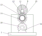
图1为本实用新型的主视剖面结构示意图;Fig. 1 is the front sectional structure schematic diagram of the utility model;
图2为本实用新型的侧视结构示意图;Fig. 2 is the side view structure schematic diagram of the utility model;
图3为本实用新型的压缩板剖面结构示意图;Fig. 3 is the sectional structure schematic diagram of the compression plate of the utility model;
图4为本实用新型的除尘板剖面结构示意图;Fig. 4 is a schematic diagram of the cross-sectional structure of the dust removal board of the present utility model;
图5为本实用新型的系统框架结构示意图。FIG. 5 is a schematic diagram of the system frame structure of the present invention.
附图标记说明:1、底板;2、外壳;3、控制面板;4、滚筒;5、压缩板;6、第一电机;7、第一转轴;8、转杆;9、打磨片;10、打磨孔;11、安装箱;12、气缸;13、从动齿轮;14、预埋管;15、导风罩;16、第二电机;17、第二转轴;18、主动齿轮;19、固定板;20、风机;21、除尘板;22、减噪棉块;23、中空框板;24、换气孔;25、缓冲气囊筒;26、玻璃棉;27、过滤网;28、吸尘棉层。Description of reference numerals: 1. Bottom plate; 2. Housing; 3. Control panel; 4. Drum; 5. Compression plate; 6. First motor; 7. First rotating shaft; , grinding hole; 11, installation box; 12, cylinder; 13, driven gear; 14, embedded pipe; 15, wind guide cover; 16, second motor; 17, second shaft; 18, driving gear; 19, Fixed plate; 20. Fan; 21. Dust removal plate; 22. Noise reduction cotton block; 23. Hollow frame plate; 24. Ventilation hole; 25. Buffer air bag; 26. Glass wool; Dust cotton layer.
具体实施方式Detailed ways
参看图1-图5所示,本具体实施方式采用的技术方案是:它包含底板1、外壳2、控制面板3、滚筒4、压缩板5、第一电机6、第一转轴7、转杆8、打磨片9、打磨孔10、安装箱11、气缸12、从动齿轮13、预埋管14、导风罩15、第二电机16、第二转轴17、主动齿轮18、固定板19、风机20、除尘板21、减噪棉块22、中空框板23、换气孔24、缓冲气囊筒25、玻璃棉26、过滤网27以及吸尘棉层28,底板1的顶端焊接有外壳2,外壳2的内部安装有固定板19,固定板19的一侧固定有导风罩15,导风罩15一侧的两端皆固定有风机20,该风机20的型号可为Y112M-2,风机20的内部安装有等间距的除尘板21,除尘板21的内部设置有玻璃棉26,固定板19顶端的外壳2内部安装有滚筒4,且滚筒4的两端皆延伸至外壳2的外部,滚筒4内部的两侧皆固定有等间距的压缩板5,压缩板5内部的一端固定有中空框板23,滚筒4的内部设置有预埋管14,且预埋管14的两端皆延伸至滚筒4的外部,滚筒4的中心位置处固定有打磨孔10,滚筒4表面的一侧固定有控制面板3,该控制面板3的型号可为KTP600,且控制面板3内部单片机的输出端与风机20的输入端电性连接,底板1顶部的一端固定有第二电机16,该第二电机16的型号可为Y90S-2,且第二电机16的输入端与控制面板3内部单片机的输出端电性连接,第二电机16的输出端通过联轴器安装有第二转轴17,第二转轴17的表面套装有主动齿轮18,滚筒4表面的一端套装有从动齿轮13,且从动齿轮13与主动齿轮18相互齿合,外壳2顶部的打磨孔10位置处设置有打磨片9,打磨片9的内部固定有转杆8,且转杆8的两端皆延伸至打磨片9的外部,打磨片9两侧的外壳2顶端皆固定有气缸12,该气缸12的型号可为NDMD20-40D,且气缸12的输入端与控制面板3内部单片机的输出端电性连接,打磨片9一侧的气缸12顶部安装有安装箱11,且转杆8的一端与安装箱11相互铰接,打磨片9远离安装箱11一侧的气缸12顶部固定有第一电机6,且第一电机6的输入端与控制面板3内部单片机的输出端电性连接;1-5, the technical solution adopted in this specific embodiment is: it includes a
所述外壳2内部的底端安装有等间距的减噪棉块22,用于减少噪音;The bottom end inside the
所述压缩板5的内部安装有换气孔24,用于压缩板5的缓冲工作;The inside of the
所述第一电机6的输出端通过联轴器安装有第一转轴7,且第一转轴7远离第一电机6的一端与转杆8远离安装箱11的一端固定连接,用于连接使其进行转动;The output end of the first motor 6 is installed with a first rotating shaft 7 through a coupling, and the end of the first rotating shaft 7 away from the first motor 6 is fixedly connected with the end of the rotating rod 8 away from the
所述中空框板23的内部安装有等间距的缓冲气囊筒25,用于进行压缩;The inside of the
所述玻璃棉26的一侧固定有过滤网27,用于过滤切割产生的灰尘;A
所述过滤网27远离玻璃棉26一侧的除尘板21内部安装有吸尘棉层28,用于吸附灰尘。A dust-absorbing
本实用新型的工作原理:在此切割装置使用时,首先将所需要切割的管道放置在滚筒4的内部,随后操作控制面板3使其控制第一电机6以及第二电机16的工作,第一电机6会通过第一转轴7进而带动通过转杆8驱动打磨片9在外壳2的上方高速旋转,打磨片9会在滚筒4顶部的打磨孔10位置处与预埋管14相互接触,在打磨片9对预埋管14进行切割的同时,第二电机16会通过第二转轴17进而带动其表面套装的主动齿轮18进行旋转,主动齿轮18进而带动从动齿轮13使滚筒4在外壳2的内部进行匀速旋转,能够提高装置使用时的切割效果,切割的同时控制面板3会控制风机20进行工作,风机20会通过导风罩15将外壳2内部切割产生的灰尘送至除尘板21的内部,通过除尘板21内部玻璃棉26、过滤网27以及吸尘棉层28的相互配合,实现了装置的除尘排废功能,从而改善了装置使用时的工作环境,最后当预埋管14在滚筒4的内部旋转时,滚筒4内部与预埋管14接触的压缩板5经过压缩会将空气经换气孔24排出,同时与中空框板23以及缓冲气囊筒25相互配合工作,使其旋转时切割的稳定性有所提高,完成切割装置的工作。The working principle of the present utility model: when the cutting device is used, the pipe to be cut is first placed inside the drum 4, and then the
采用上述技术方案后,本实用新型有益效果为:结构操作较为简便,同时使用时会减少使用时造成的环境未然,切割的时较为稳定,切割效果好,在同行领域中性能优越且推广性强。After the above technical scheme is adopted, the beneficial effects of the utility model are: the structure and operation are relatively simple, and the environment caused by the use during use will be reduced at the same time, the cutting process is relatively stable, the cutting effect is good, and the performance is superior in the field of the same industry. .
以上所述,仅用以说明本实用新型的技术方案而非限制,本领域普通技术人员对本实用新型的技术方案所做的其它修改或者等同替换,只要不脱离本实用新型技术方案的精神和范围,均应涵盖在本实用新型的权利要求范围当中。The above is only used to illustrate the technical solution of the present invention and not to limit it. Other modifications or equivalent replacements made by those of ordinary skill in the art to the technical solution of the present invention are not departing from the spirit and scope of the technical solution of the present invention. , should be included in the scope of the claims of the present utility model.
Claims (7)
Priority Applications (1)
| Application Number | Priority Date | Filing Date | Title |
|---|---|---|---|
| CN201920431126.2U CN209902921U (en) | 2019-04-01 | 2019-04-01 | Quick and stable cutting device of pre-buried pipe |
Applications Claiming Priority (1)
| Application Number | Priority Date | Filing Date | Title |
|---|---|---|---|
| CN201920431126.2U CN209902921U (en) | 2019-04-01 | 2019-04-01 | Quick and stable cutting device of pre-buried pipe |
Publications (1)
| Publication Number | Publication Date |
|---|---|
| CN209902921U true CN209902921U (en) | 2020-01-07 |
Family
ID=69034680
Family Applications (1)
| Application Number | Title | Priority Date | Filing Date |
|---|---|---|---|
| CN201920431126.2U Expired - Fee Related CN209902921U (en) | 2019-04-01 | 2019-04-01 | Quick and stable cutting device of pre-buried pipe |
Country Status (1)
| Country | Link |
|---|---|
| CN (1) | CN209902921U (en) |
Cited By (2)
| Publication number | Priority date | Publication date | Assignee | Title |
|---|---|---|---|---|
| CN111958398A (en) * | 2020-08-31 | 2020-11-20 | 莫一全 | Optical lens machining device capable of controlling polishing time length through air bag clamping rotation |
| CN116652721A (en) * | 2023-04-20 | 2023-08-29 | 山东雷欧机床有限公司 | A vertical lathe surface grinding device |
-
2019
- 2019-04-01 CN CN201920431126.2U patent/CN209902921U/en not_active Expired - Fee Related
Cited By (2)
| Publication number | Priority date | Publication date | Assignee | Title |
|---|---|---|---|---|
| CN111958398A (en) * | 2020-08-31 | 2020-11-20 | 莫一全 | Optical lens machining device capable of controlling polishing time length through air bag clamping rotation |
| CN116652721A (en) * | 2023-04-20 | 2023-08-29 | 山东雷欧机床有限公司 | A vertical lathe surface grinding device |
Similar Documents
| Publication | Publication Date | Title |
|---|---|---|
| CN209953312U (en) | Dust removal device for automobile filter | |
| CN107009418B (en) | A kind of plastic pipe fitting cutting machine structure with dust exhaust apparatus | |
| CN213034163U (en) | A vacuum cleaner for a cutting machine | |
| CN214291069U (en) | Aluminum-based copper-clad plate production and processing device | |
| CN216228572U (en) | A CNC grinding device that automatically collects waste chips | |
| CN211248520U (en) | A kind of plate shearing machine for processing railway pier body formwork | |
| CN214133113U (en) | A glass nondestructive cutting device for dismantling scrapped automobiles | |
| CN210676206U (en) | Mechanical industry dust collecting equipment | |
| CN204673705U (en) | Automatic waste discharge rotates cutting head | |
| CN215470416U (en) | Burnishing machine with suction hood | |
| CN214269068U (en) | A dust removal device for chemical fertilizer raw material processing | |
| CN212917855U (en) | Cutting device is carried to building materials | |
| CN211967025U (en) | High-load type mining car frame surface grinding device | |
| CN212599647U (en) | Air suction device for laser cutting equipment | |
| CN210820286U (en) | Green cutting device of scraped car glass | |
| CN222726913U (en) | Negative pressure suction type wood board production scrap collecting device | |
| CN207372857U (en) | A kind of building wall construction sander | |
| CN211438393U (en) | Cutting device is used in aluminum alloy ex-trusions processing | |
| CN219027070U (en) | Steel construction rust cleaning device | |
| CN223544912U (en) | A grinding device for automobile horn production | |
| CN223313673U (en) | A burr removal device for glass clip production | |
| CN219518186U (en) | Environment-friendly dust removing device for putty powder production | |
| CN222175066U (en) | Low frequency sound absorbing board surface treatment device | |
| CN221818846U (en) | Composite floor cutting device | |
| CN224129328U (en) | A damping plate processing edge grinding structure |
Legal Events
| Date | Code | Title | Description |
|---|---|---|---|
| GR01 | Patent grant | ||
| GR01 | Patent grant | ||
| CF01 | Termination of patent right due to non-payment of annual fee | ||
| CF01 | Termination of patent right due to non-payment of annual fee |
Granted publication date: 20200107 |