CN209899246U - Automatic disinfection device for toilet cover plate and toilet - Google Patents
Automatic disinfection device for toilet cover plate and toilet Download PDFInfo
- Publication number
- CN209899246U CN209899246U CN201920365871.1U CN201920365871U CN209899246U CN 209899246 U CN209899246 U CN 209899246U CN 201920365871 U CN201920365871 U CN 201920365871U CN 209899246 U CN209899246 U CN 209899246U
- Authority
- CN
- China
- Prior art keywords
- toilet
- atomizing
- atomization
- pipe
- cover
- Prior art date
- Legal status (The legal status is an assumption and is not a legal conclusion. Google has not performed a legal analysis and makes no representation as to the accuracy of the status listed.)
- Active
Links
Images






Landscapes
- Bidet-Like Cleaning Device And Other Flush Toilet Accessories (AREA)
- Apparatus For Disinfection Or Sterilisation (AREA)
- Toilet Supplies (AREA)
Abstract
本实用新型公开了一种座便器盖板自动消毒装置及座便器,所述座便器盖板自动消毒装置包括转动连接在一起的上盖和座圈,还包括雾化装置、雾化输送管、用于向座圈喷射消毒雾气的喷雾机构,喷雾机构设置在上盖,并通过雾化输送管连接所述雾化装置。本实用新型能够将消毒液通过雾化装置转化为消毒雾气,再通过喷雾机构使消毒雾气均匀覆盖在座圈表面,不仅消毒面积广、消毒液分布均匀,还能大大提高消毒液的利用率,降低消毒液的使用量,以及提高座圈表面的消毒液的干燥速度,以免影响使用。
The utility model discloses an automatic sterilizing device for a toilet cover and a toilet. The automatic sterilizing device for the toilet cover comprises an upper cover and a seat ring which are rotatably connected together, and further comprises an atomizing device, an atomizing conveying pipe, The spraying mechanism is used for spraying the sterilizing mist to the seat ring, the spraying mechanism is arranged on the upper cover, and is connected to the atomizing device through the atomizing conveying pipe. The utility model can convert the disinfectant into a disinfectant mist through an atomizing device, and then use the spray mechanism to make the disinfectant mist evenly cover the surface of the seat ring. The amount of disinfectant used, and the drying speed of the disinfectant on the surface of the seat ring, so as not to affect the use.
Description
技术领域technical field
本实用新型涉及卫浴领域,特别是涉及一种座便器盖板自动消毒装置及座便器。The utility model relates to the field of sanitary ware, in particular to an automatic sterilizing device for a toilet cover plate and a toilet.
背景技术Background technique
座便器,俗称马桶,有效解决了人们如厕久蹲对腿部血管和神经挤压导致的腿麻、头晕等不适,尤其对于孕妇、老人、各种病人等,座便器更是备受青睐。由于座便器在使用时,其座圈与人体臀部直接接触,而座便器往往被不同的人使用,特别是设置在诸如医院、各大商场、酒店等场所的座便器,更是被不同的人频繁使用,且座圈又不经常被及时清洗、消毒,导致座圈容易滋长细菌和造成交叉感染。The toilet, commonly known as the toilet, effectively solves the discomfort of leg numbness and dizziness caused by the compression of blood vessels and nerves in the legs caused by people squatting on the toilet for a long time. Especially for pregnant women, the elderly, and various patients, the toilet is more popular. When the toilet is in use, the seat ring is in direct contact with the buttocks of the human body, and the toilet is often used by different people, especially the toilet set in places such as hospitals, shopping malls, hotels, etc., which are used by different people. Frequent use, and the seat ring is not often cleaned and disinfected in time, which makes the seat ring easy to grow bacteria and cause cross-infection.
为此,现有技术出现了一种自消毒座便器盖,它在盖板底面设置带喷液孔的消毒液腔,消毒液腔通过导管与消毒液罐连接,消毒液罐与脚踏喷液开关配合。这种座便器盖能够在一定程度上对座圈起到消毒杀菌的作用,但由于其是将消毒液直接以完全液态的形式喷在座圈上,导致消毒液的使用量较大、消毒液利用率低,且座圈表面的消毒液分布不均匀,也不易快干。For this reason, a self-disinfecting toilet cover has appeared in the prior art, which is provided with a disinfectant chamber with a liquid spray hole on the bottom surface of the cover plate, the disinfectant chamber is connected with a disinfectant tank through a conduit, and the disinfectant tank is connected with a foot spray for liquid switch fit. This kind of toilet cover can sterilize and sterilize the seat ring to a certain extent, but because the disinfectant is directly sprayed on the seat ring in a completely liquid form, the usage of disinfectant is relatively large, and the use of disinfectant The rate is low, and the distribution of the disinfectant on the surface of the seat ring is uneven, and it is not easy to dry quickly.
实用新型内容Utility model content
本实用新型提供了一种座便器盖板自动消毒装置及座便器,其克服了现有技术的自消毒座便器盖所存在的不足之处。The utility model provides an automatic sterilizing device for a toilet cover and a toilet, which overcome the shortcomings of the self-sterilizing toilet cover in the prior art.
本实用新型解决其技术问题所采用的技术方案是:一种座便器盖板自动消毒装置,包括转动连接在一起的上盖和座圈,还包括雾化装置、雾化输送管、用于向座圈喷射消毒雾气的喷雾机构,喷雾机构设置在上盖,并通过雾化输送管连接所述雾化装置。The technical scheme adopted by the utility model to solve the technical problem is as follows: an automatic sterilizing device for a toilet cover plate, which includes an upper cover and a seat ring that are rotatably connected together, and also includes an atomizing device, an atomizing conveying pipe, and a The seat ring is a spray mechanism for spraying disinfectant mist, the spray mechanism is arranged on the upper cover, and is connected to the atomization device through an atomization conveying pipe.
进一步的,所述喷雾机构包括布置于所述上盖内侧的喷雾管,该喷雾管朝向所述座圈的一面设置多个喷雾孔。Further, the spray mechanism includes a spray pipe arranged inside the upper cover, and a surface of the spray pipe facing the seat ring is provided with a plurality of spray holes.
进一步的,所述喷雾管的数量为两条,该两喷雾管分别布置于上盖的左部和右部,且该两喷雾管的一端封闭,并位于上盖前端,该两喷雾管的另一端分别位于上盖后端,并通过一三通管接通所述雾化输送管的一端,所述雾化输送管的另一端连接所述雾化装置。Further, the number of the spray pipes is two, the two spray pipes are respectively arranged on the left part and the right part of the upper cover, and one end of the two spray pipes is closed and located at the front end of the upper cover, and the other side of the two spray pipes is closed. One end is respectively located at the rear end of the upper cover, and is connected to one end of the atomization conveying pipe through a three-way pipe, and the other end of the atomization conveying pipe is connected to the atomizing device.
进一步的,所述上盖内侧还连接有装饰盖,对所述喷雾管进行遮挡,且装饰盖上设有与所述喷雾孔对应的过雾孔。Further, a decorative cover is also connected to the inner side of the upper cover to shield the spray pipe, and the decorative cover is provided with a fog hole corresponding to the spray hole.
进一步的,所述雾化输送管包括第一输送管和第二输送管,第二输送管一端连接一连接套,另一端连接所述雾化装置;第一输送管一端接通所述喷雾机构,另一端在所述上盖闭合时插入所述连接套;所述连接套固定在座便器的后盖上。Further, the atomization conveying pipe includes a first conveying pipe and a second conveying pipe, one end of the second conveying pipe is connected to a connecting sleeve, and the other end is connected to the atomizing device; one end of the first conveying pipe is connected to the spray mechanism. , the other end is inserted into the connecting sleeve when the upper cover is closed; the connecting sleeve is fixed on the back cover of the toilet.
进一步的,所述雾化装置包括装载消毒液的盒体,以及设置于盒体的风机、出雾管、雾化片、电路板、发热元件,雾化片、风机、发热元件均与电路板电连接,且雾化片位于盒体的内腔底部,风机启动时向所述出雾管送风,发热元件位于风机的出风口处;出雾管接通所述雾化输送管和盒体内腔。Further, the atomizing device includes a box body loaded with disinfectant, and a fan, a mist outlet pipe, an atomizing sheet, a circuit board, and a heating element arranged in the box body, and the atomizing sheet, the fan, and the heating element are all connected with the circuit board. It is electrically connected, and the atomizing sheet is located at the bottom of the inner cavity of the box body. When the fan is started, air is supplied to the mist outlet pipe, and the heating element is located at the air outlet of the fan; the mist outlet pipe is connected to the atomization conveying pipe and the box body. cavity.
进一步的,所述盒体包括可分离的上、下两层壳体,上层壳体设置储液腔,下层壳体设置雾化腔,且上层壳体的储液腔底端设置连通所述雾化腔的下水口,该下水口处安装有止水组件,该止水组件在上层壳体和下层壳体分离时关闭下水口;所述风机、电路板、发热元件设置于下层壳体,所述雾化片设置在雾化腔底部;所述出雾管设置于上层壳体,且出雾管底端通向下层壳体的雾化腔。Further, the box body includes separable upper and lower shells, the upper shell is provided with a liquid storage cavity, the lower shell is provided with an atomization cavity, and the bottom end of the liquid storage cavity of the upper shell is provided with a connection to the mist. The water outlet of the chemical chamber, a water stop assembly is installed at the water outlet, and the water stop assembly closes the water outlet when the upper shell and the lower shell are separated; the fan, the circuit board and the heating element are arranged in the lower shell, so The atomizing sheet is arranged at the bottom of the atomization cavity; the mist outlet pipe is arranged in the upper shell, and the bottom end of the mist outlet pipe leads to the atomization cavity of the lower shell.
进一步的,所述止水组件上设置有用于限制所述雾化腔的最高水位的过水缺口,该过水缺口上缘低于所述雾化腔顶面,并在所述下水口开启状态连通所述储液腔;和/或,Further, the water stop component is provided with a water passage gap for limiting the highest water level of the atomization chamber, the upper edge of the water passage gap is lower than the top surface of the atomization chamber, and the water outlet is in the open state. communicating with the reservoir; and/or,
所述下层壳体中还设置用于防止所述雾化片干烧的水位开关,该水位开关包括浮子、霍尔基板,浮子上设置磁铁,霍尔基板与所述电路板电连接,当浮子在所述雾化腔中下落时,霍尔基板上的霍尔元件感应到磁铁而切断电路。The lower shell is also provided with a water level switch for preventing the atomizing sheet from drying out. The water level switch includes a float and a Hall substrate. The float is provided with a magnet, and the Hall substrate is electrically connected to the circuit board. When falling in the atomizing chamber, the Hall element on the Hall substrate senses the magnet and cuts off the circuit.
本实用新型另提供一种座便器,包括座便器本体,还包括上述本实用新型所述的座便器盖板自动消毒装置,所述上盖和座圈设置在座便器本体上。The utility model further provides a toilet, which includes a toilet body, and also includes the toilet cover automatic sterilizing device of the present utility model. The upper cover and the seat ring are arranged on the toilet body.
进一步的,所述雾化装置连接在所述座便器本体左侧或右侧设置的侧按板上,或者,所述雾化装置放置在座便器的水箱上或地面上。Further, the atomizing device is connected to the side pressing plate provided on the left or right side of the toilet body, or the atomizing device is placed on the water tank of the toilet or on the ground.
相较于现有技术,本实用新型具有以下有益效果:Compared with the prior art, the utility model has the following beneficial effects:
1、所述雾化装置、雾化输送管、喷雾机构的设置,使本实用新型能够将消毒液通过雾化装置转化为消毒雾气,再通过喷雾机构使消毒雾气均匀覆盖在座圈表面,不仅消毒面积广、消毒液分布均匀,还能大大提高消毒液的利用率,降低消毒液的使用量,以及提高座圈表面的消毒液的干燥速度,以免影响使用。1. The setting of the atomizing device, the atomizing conveying pipe and the spraying mechanism enables the present utility model to convert the disinfectant into a disinfecting mist through the atomizing device, and then make the disinfecting mist evenly cover the surface of the seat ring through the spraying mechanism, not only disinfecting It has a wide area and uniform distribution of the disinfectant, which can greatly improve the utilization rate of the disinfectant, reduce the usage of the disinfectant, and improve the drying speed of the disinfectant on the surface of the seat ring, so as not to affect the use.
2、所述雾化输送管包括所述第一输送管和第二输送管,第一输送管和第二输送管通过所述连接套配合上盖启闭实现接通与否,能够使上盖启闭时,雾化输送管不会被拉扯,从而确保雾化输送管不容易损坏,使用寿命长。2. The atomization conveying pipe includes the first conveying pipe and the second conveying pipe. The first conveying pipe and the second conveying pipe are connected through the opening and closing of the upper cover through the connection sleeve, so that the upper cover can be opened or closed. When opening and closing, the atomizing conveying pipe will not be pulled, so as to ensure that the atomizing conveying pipe is not easily damaged and has a long service life.
3、所述雾化装置包括所述盒体、风机、出雾管、雾化片、电路板、发热元件,不仅能够将消毒液快速转换为消毒雾气,缩短使用者等待消毒的时间,还能够利用发热元件配合风机吹出热风,以在座圈表面消毒后吹干座圈表面,从而进一步缩短使用者等待使用座便器的时间。3. The atomizing device includes the box body, the fan, the mist outlet pipe, the atomizing sheet, the circuit board, and the heating element, which can not only quickly convert the disinfectant into a disinfection mist, shorten the time for users to wait for disinfection, but also The heating element and the blower are used to blow out hot air, so as to dry the surface of the seat ring after the surface of the seat ring is disinfected, thereby further shortening the time for the user to wait for the toilet to be used.
4、所述过水缺口的设置,能够有效控制储液腔向雾化腔的补液量。4. The setting of the water passage gap can effectively control the liquid replenishment amount from the liquid storage chamber to the atomizing chamber.
以下结合附图及实施例对本实用新型作进一步详细说明;但本实用新型的一种座便器盖板自动消毒装置及座便器不局限于实施例。The present utility model will be described in further detail below with reference to the accompanying drawings and embodiments; however, the present utility model is not limited to the embodiments of an automatic sterilizing device for a toilet seat cover plate and a toilet seat.
附图说明Description of drawings
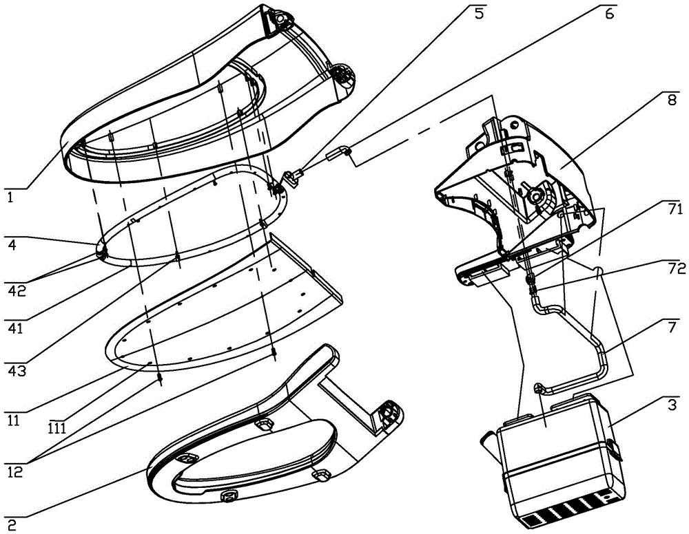
图1是本实用新型的座便器盖板自动消毒装置的分解示意图;Fig. 1 is the exploded schematic diagram of the automatic sterilizing device for toilet cover plate of the present invention;
图2是本实用新型的座便器盖板自动消毒装置安装于座便器本体上的结构示意图;2 is a schematic structural diagram of the automatic toilet cover plate disinfection device of the present utility model installed on the toilet body;
图3是图2的剖视图;Fig. 3 is the sectional view of Fig. 2;
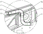
图4是图3中A部分的放大示意图;Fig. 4 is the enlarged schematic diagram of part A in Fig. 3;
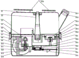
图5是本实用新型的雾化装置的剖视图;5 is a cross-sectional view of the atomizing device of the present invention;
图6是本实用新型的雾化装置的局部结构的分解示意图;6 is an exploded schematic view of the partial structure of the atomizing device of the present invention;
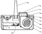
图7是本实用新型的雾化装置的局部结构的剖视图;Fig. 7 is the sectional view of the partial structure of the atomizing device of the present utility model;
图8是本实用新型的上层壳体的外壳的结构示意图;8 is a schematic structural diagram of the outer shell of the upper shell of the present invention;
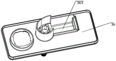
图9是本实用新型的上层壳体的底座的结构示意图一;Fig. 9 is the first structural schematic diagram of the base of the upper shell of the present invention;
图10是本实用新型的上层壳体的底座的结构示意图二;10 is a second structural schematic diagram of the base of the upper shell of the present invention;
图11是本实用新型的下层壳体的上壳的结构示意图一;Fig. 11 is the first structural schematic diagram of the upper shell of the lower shell of the present invention;
图12是本实用新型的下层壳体的上壳的结构示意图二;12 is a second structural schematic diagram of the upper shell of the lower shell of the present invention;
图13是本实用新型的连接盖的结构示意图一;Fig. 13 is the first structural schematic diagram of the connecting cover of the present invention;
图14是本实用新型的连接盖的结构示意图二。FIG. 14 is a second structural schematic diagram of the connecting cover of the present invention.
具体实施方式Detailed ways
实施例,请参见图1-图14所示,本实用新型的一种座便器盖板自动消毒装置,包括转动连接在一起的上盖1和座圈2,还包括雾化装置3、雾化输送管、用于向座圈2喷射消毒雾气的喷雾机构,喷雾机构设置在上盖1,并通过雾化输送管连接所述雾化装置3。For an embodiment, please refer to Fig. 1-Fig. 14. An automatic disinfection device for a toilet cover of the present invention includes an
本实施例中,所述喷雾机构包括布置于所述上盖1内侧(所述上盖内侧指上盖1面向座圈2的一侧)的喷雾管4,该喷雾管4朝向所述座圈2的一面均匀布置多个喷雾孔41。所述喷雾管4的数量具体为两条,但不局限于此,在其它实施例中,所述喷雾管4的数量为一条。两喷雾管4分别布置于上盖1的左部和右部,且该两喷雾管4具体分别由若干压片42进行固定,各压片42分别通过螺钉43锁在上盖1上。两喷雾管4的一端封闭,并位于上盖1前端,该两喷雾管4的另一端分别位于上盖1后端,并通过一三通管5接通所述雾化输送管的一端,所述雾化输送管的另一端连接所述雾化装置3。所述上盖1内侧还通过螺钉12连接有装饰盖11,对所述喷雾管4进行遮挡,且装饰盖11上设有与所述喷雾孔41对应的过雾孔111。所述喷雾管4具体为软管,但不局限于此。In this embodiment, the spray mechanism includes a
本实施例中,所述雾化输送管包括第一输送管6和第二输送管7,第一输送管6较短,并为大致呈L字形的弯管,第二输送管7为长软管,且该第二输送管7一端连接一连接套71,连接套71具体通过螺钉72固定在座便器的后盖8上。第二输送管7另一端连接所述雾化装置3。该第一输送管6固定在所述上盖1上,第一输送管6一端接通所述喷雾机构,具体第一输送管6一端通过所述三通管5接通所述喷雾管4的另一端。第一输送管6另一端在所述上盖1闭合时插入所述连接套71。In this embodiment, the atomization conveying pipe includes a first conveying
本实施例中,所述雾化装置3包括装载消毒液的盒体,以及设置于盒体的风机310、出雾管32、雾化片317、电路板316、发热元件330,雾化片317、风机310、发热元件330均与电路板316电连接,且雾化片317位于盒体的内腔底部,风机310启动时向所述出雾管32送风,发热元件330位于风机310的出风口处;出雾管32接通所述雾化输送管和盒体内腔,亦即,出雾管32顶端接通所述第二输送管7的另一端,出雾管32底端正对所述雾化片317。In this embodiment, the
本实施例中,所述盒体包括可分离的上、下两层壳体,上层壳体设置储液腔,下层壳体设置雾化腔,且上层壳体的储液腔底端设置连通所述雾化腔的下水口361,该下水口361处安装有止水组件,该止水组件在上层壳体和下层壳体分离时关闭下水口361;所述风机310、电路板316、发热元件330设置于下层壳体,所述雾化片317设置在雾化腔底部;所述出雾管32设置于上层壳体,且出雾管32底端通向下层壳体的雾化腔。In this embodiment, the box body includes separable upper and lower shells, the upper shell is provided with a liquid storage cavity, the lower shell is provided with an atomization cavity, and the bottom end of the liquid storage cavity of the upper shell is provided with a communication The
本实施例中,所述止水组件上设置有用于限制所述雾化腔的最高水位的过水缺口3212,该过水缺口3212上缘低于所述雾化腔顶面,并在所述下水口361开启状态连通所述储液腔。所述止水组件具体包括设置过水口的旋盖321、止水垫325、顶销323、压簧322、旋盖321套设有密封圈324,并旋接在所述下水口361处,具体,所述下水口361内侧面周向布置若干第一扣条362,旋盖321上对应布置若干第二扣条3211,第一扣条362与第二扣条3211对应扣合。顶销323套设在旋盖321的过水口中,止水垫325设置在顶销323顶部,并配合在旋盖321的过水口上侧,压簧322套在顶销323上,并抵设在顶销323底部与旋盖321之间。所述雾化腔底端在与顶销323对应的位置处设有支柱371,当上层壳体装在下层壳体上时,该支柱371顶起顶销323,止水垫325被抬起,从而开启旋盖321的过水口,使储液腔中的消毒液流入雾化腔中。所述过水缺口3212即设在旋盖321的底部侧壁上。In this embodiment, the water-stop component is provided with a water-passing
本实施例中,所述下层壳体中还设置用于防止所述雾化片317干烧的水位开关,该水位开关包括浮子39、霍尔基板311,浮子39内镶一磁铁,霍尔基板311与所述电路板316电连接,当浮子39在所述雾化腔中下落时,霍尔基板311上的霍尔元件感应到磁铁而切断电路。所述浮子39具体套设在所述雾化腔底部设置的一中空导柱373上,中空导柱373顶部套设定位帽34,以限制浮子39脱离导柱373。所述霍尔基板311通过一固定片312配合螺钉313锁在下层壳体,并局部伸入中空导柱373内。在其它实施例中,所述水位开关为液位感应器等。In this embodiment, a water level switch for preventing the
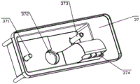
本实施例中,所述上层壳体侧面设置加液管,该加液管一端连通所述储液腔,另一端设置可启闭的加液盖327,打开加液盖327即可往储液腔中补充消毒液(该消毒液优选医用快干免洗消毒液),加液盖327上设置有密封圈326,起密封作用,防止储液腔中的消毒液溅出。所述上层壳体具体包括外壳33、底座36,外壳33底端与底座36连接,与之围成所述储液腔,所述下水口361、出雾管32设置于底座36,且出雾管32顶端穿过外壳33顶端,并旋接有蝶形螺母31。所述下层壳体具体包括上壳37和下壳314,上壳37设置所述雾化腔,并安装有所述风机310、电路板316、发热元件330,所述雾化片317具体通过雾化座320配合密封圈319、雾化固定板315、雾化密封圈318安装在上壳37底端设置的安装口372处,且雾化片317与所述过水缺口3212上缘的垂直距离为35mm,亦即,雾化片317作用面以上有35mm的高度的液体,能使雾化片317产生最大的雾化量。上壳37与所述底座36上下对接,下壳314包裹上壳37,并与上层壳体的外壳33呈可拆卸式连接,具体,上层壳体的外壳33底部外侧门采用销钉35转动连接有扣钩38,与下层壳体的下壳314外侧面设置的倒钩卡扣连接。所述底座36在与所述风机310对应的位置处设有上凸的反射腔363,该反射腔363连通所述出雾管32底端,风机310产生的风进入反射腔反射后输向出雾管32。所述风机310具体安装在所述上壳37底端,且上壳37设置与风机310对应的出风口374,所述发热元件330具体通过螺钉332配合隔热垫片329、隔热片331锁在上壳37靠近出风口374的位置处。所述发热元件330具体可以是发热金属管或电阻丝等。所述支柱371、导柱373、霍尔基板311均设置于所述上壳37。In this embodiment, a liquid filling pipe is arranged on the side of the upper shell. One end of the liquid filling pipe is connected to the liquid storage cavity, and the other end is provided with a
本实施例中,所述雾化装置3连接在座便器左侧或右侧设置的侧按板10上,具体,所述上层壳体的外壳33顶端设置两个卡勾328,使雾化装置3挂在所述侧按板10上。在其它实施例中,所述雾化装置放置在座便器的水箱上或地面上。In this embodiment, the
本实用新型的一种座便器盖板自动消毒装置,当要消毒时,闭合上盖1,位于上盖1后部的第一输送管6插入连接套71内,导通第二输送管7;启动雾化装置3,雾化片317和风机310同时工作,雾化片317高频振动,在雾化腔中的消毒液的上表面产生大量消毒雾气,该消毒雾气在风机310作用下,依次通过出雾管32、第二输送管7、第一输送管6、三通管5,一分为二后同步进入两条喷雾管4,再从均匀分布在喷雾管4上的喷雾孔41喷出,喷向座圈2上表面,在座圈2上表面覆盖一层薄薄的雾气,进行杀菌、消毒。雾化片317工作一定的时间(也是消毒时间)后,停止工作,风机310仍然持续运转,此时在风机310的出风口处的发热元件330自动启动,热空气在风机310作用下,依次通过出雾管32、第二输送管7、第一输送管6、三通管5,一分为二后同步进入两个喷雾管4,再从均匀分布在喷雾管4上的喷雾孔41喷出,喷向座圈2上表面,对座圈2上表面进行快速吹干。一定时间后风机310停止工作,整个消毒、吹干座圈2的动作结束。所述风机310在消毒阶段和吹干阶段可以采用同一种功率,也可以在吹干阶段用更高的功率,使吹干速度更快。The utility model is an automatic sterilizing device for a toilet cover plate. When sterilizing, the
请参见图1-图14所示,本实用新型的一种座便器,包括座便器本体9,以及上述本实用新型所述的一种座便器盖板自动消毒装置,所述上盖1和座圈2设置在座便器本体9上。所述雾化装置3挂在座便器本体左侧设置的侧按板10上,所述雾化装置3的启动按键可以设置在所述侧按板10上,也可以设置在雾化装置3的上层壳体或下层壳体上,或者,设置在座便器的遥控器上。Please refer to FIGS. 1-14 , a toilet of the present invention includes a toilet body 9 , and the above-mentioned automatic sterilizing device for a toilet cover of the present invention, the
本实用新型的一种座便器,其座圈2的消毒过程如上所述,因此,此处不再进一步赘述。In a toilet of the present invention, the sterilization process of the
上述实施例仅用来进一步说明本实用新型的一种座便器盖板自动消毒装置及座便器,但本实用新型并不局限于实施例,凡是依据本实用新型的技术实质对以上实施例所作的任何简单修改、等同变化与修饰,均落入本实用新型技术方案的保护范围内。The above-mentioned embodiments are only used to further illustrate a kind of automatic sterilizing device for toilet cover and the toilet of the present invention, but the present invention is not limited to the embodiments, and all the above-mentioned embodiments are made according to the technical essence of the present invention. Any simple modification, equivalent change and modification all fall within the protection scope of the technical solution of the present invention.
Claims (10)
Priority Applications (1)
| Application Number | Priority Date | Filing Date | Title |
|---|---|---|---|
| CN201920365871.1U CN209899246U (en) | 2019-03-21 | 2019-03-21 | Automatic disinfection device for toilet cover plate and toilet |
Applications Claiming Priority (1)
| Application Number | Priority Date | Filing Date | Title |
|---|---|---|---|
| CN201920365871.1U CN209899246U (en) | 2019-03-21 | 2019-03-21 | Automatic disinfection device for toilet cover plate and toilet |
Publications (1)
| Publication Number | Publication Date |
|---|---|
| CN209899246U true CN209899246U (en) | 2020-01-07 |
Family
ID=69033325
Family Applications (1)
| Application Number | Title | Priority Date | Filing Date |
|---|---|---|---|
| CN201920365871.1U Active CN209899246U (en) | 2019-03-21 | 2019-03-21 | Automatic disinfection device for toilet cover plate and toilet |
Country Status (1)
| Country | Link |
|---|---|
| CN (1) | CN209899246U (en) |
Cited By (4)
| Publication number | Priority date | Publication date | Assignee | Title |
|---|---|---|---|---|
| CN111305339A (en) * | 2020-03-30 | 2020-06-19 | 九牧厨卫股份有限公司 | A kind of isolation and disinfecting device, intelligent toilet and isolation and disinfecting method thereof |
| CN113266062A (en) * | 2020-02-16 | 2021-08-17 | 厦门科牧智能技术有限公司 | Device and method capable of inhibiting aerosol transmission and disinfection and toilet bowl |
| CN115053040A (en) * | 2021-01-08 | 2022-09-13 | 萨尼克斯有限公司 | Self-cleaning toilet seat assembly |
| US12507845B2 (en) | 2021-10-06 | 2025-12-30 | Kohler Co. | Toilet seat hinge assembly with air cleaner |
-
2019
- 2019-03-21 CN CN201920365871.1U patent/CN209899246U/en active Active
Cited By (4)
| Publication number | Priority date | Publication date | Assignee | Title |
|---|---|---|---|---|
| CN113266062A (en) * | 2020-02-16 | 2021-08-17 | 厦门科牧智能技术有限公司 | Device and method capable of inhibiting aerosol transmission and disinfection and toilet bowl |
| CN111305339A (en) * | 2020-03-30 | 2020-06-19 | 九牧厨卫股份有限公司 | A kind of isolation and disinfecting device, intelligent toilet and isolation and disinfecting method thereof |
| CN115053040A (en) * | 2021-01-08 | 2022-09-13 | 萨尼克斯有限公司 | Self-cleaning toilet seat assembly |
| US12507845B2 (en) | 2021-10-06 | 2025-12-30 | Kohler Co. | Toilet seat hinge assembly with air cleaner |
Similar Documents
| Publication | Publication Date | Title |
|---|---|---|
| CN104645436B (en) | A seating medicine liquid washing device | |
| CN107700620B (en) | Intelligent squatting toilet | |
| CN206333876U (en) | A kind of ozone sterilizing dish washing mechine | |
| CN103735376B (en) | A kind of intelligent nursing mattress | |
| CN104623756B (en) | A seating circulating medical solution flusher | |
| CN204016176U (en) | A kind of Intelligent toilet cover | |
| CN107693806A (en) | A kind of sterilizing cabinet with cleaning function | |
| KR100585485B1 (en) | Bidet toilet seat and toilet bowl sterilizer | |
| CN201679072U (en) | Multifunctional closestool | |
| CN107929038A (en) | A kind of vulva fumigation treatment device | |
| WO2021082101A1 (en) | Ultrasonic cleaning apparatus | |
| CN205072752U (en) | Basin body detachable hip bath ware | |
| CN220833652U (en) | Container sterilizer | |
| CN107495845A (en) | A kind of water dispenser | |
| CN2662851Y (en) | Hand induction type spraying, washing and air-drying integrated disinfection case | |
| KR200311836Y1 (en) | sterilizing chamber pot cover using steam heater | |
| CN206385617U (en) | Toilet bowl flushing device | |
| CN215406388U (en) | Integrated closestool | |
| CN206591589U (en) | A kind of intelligent closestool | |
| CN211228761U (en) | Sterilizing water tank | |
| CN205530578U (en) | Intelligence urinal | |
| CN112869614A (en) | Epidemic prevention type integrated pedestal pan with drying function and drying method thereof | |
| CN222604984U (en) | Fumigating and flushing hip bath device | |
| CN106983416A (en) | A non-scaling bathtub capable of automatic decontamination | |
| CN216854526U (en) | Baby's belt cleaning device after shitting of function disinfects in area |
Legal Events
| Date | Code | Title | Description |
|---|---|---|---|
| GR01 | Patent grant | ||
| GR01 | Patent grant |