CN209898871U - Children dining chair - Google Patents

Children dining chair Download PDF

Info

Publication number
CN209898871U
CN209898871U CN201822056683.9U CN201822056683U CN209898871U CN 209898871 U CN209898871 U CN 209898871U CN 201822056683 U CN201822056683 U CN 201822056683U CN 209898871 U CN209898871 U CN 209898871U
Authority
CN
China
Prior art keywords
backrest
locking
dining chair
seat
children
Prior art date
Legal status (The legal status is an assumption and is not a legal conclusion. Google has not performed a legal analysis and makes no representation as to the accuracy of the status listed.)
Withdrawn - After Issue
Application number
CN201822056683.9U
Other languages
Chinese (zh)
Inventor
廉金龙
盛国祥
Current Assignee (The listed assignees may be inaccurate. Google has not performed a legal analysis and makes no representation or warranty as to the accuracy of the list.)
Goodbaby Child Products Co Ltd
Original Assignee
Goodbaby Child Products Co Ltd
Priority date (The priority date is an assumption and is not a legal conclusion. Google has not performed a legal analysis and makes no representation as to the accuracy of the date listed.)
Filing date
Publication date
Application filed by Goodbaby Child Products Co Ltd filed Critical Goodbaby Child Products Co Ltd
Priority to CN201822056683.9U priority Critical patent/CN209898871U/en
Application granted granted Critical
Publication of CN209898871U publication Critical patent/CN209898871U/en
Withdrawn - After Issue legal-status Critical Current
Anticipated expiration legal-status Critical

Links

Images

Landscapes

  • Special Chairs (AREA)

Abstract

The utility model discloses a child dinning chair, be in including dining chair support and detachably setting seat subassembly on the dining chair support, seat subassembly includes bedplate and back, the bedplate with swing joint between the back, just the bedplate with the back is detachably connected respectively and is in on the dining chair support. When the child dining chair is not needed to be used, the backrest and the seat board can be respectively detached from the dining chair support and then folded, so that the problem that the seat assembly occupies a large storage space due to large overall size is effectively solved, and convenience is brought to the carrying and storage of the user when the user uses the dining chair in daily life.

Description

儿童餐椅children's dining chair

技术领域technical field

本实用新型涉及一种儿童餐椅。The utility model relates to a children's dining chair.

背景技术Background technique

儿童餐椅为幼儿就餐提供了很大的方便,儿童餐椅大多是一体可折叠的结构,现有技术中,如中国专利CN207168261U公开了一种儿童餐椅,其包括餐椅架和可拆卸地设置在餐椅架上的座兜组件,这种方式虽然能够将座兜组件与餐椅架独立开来分别打包装箱或存放,但座兜组件仍然占用较大的空间,不便于运输与存储。Children's dining chairs provide great convenience for young children to eat. Most of the children's dining chairs are integrated and foldable structures. In the prior art, such as Chinese patent CN207168261U, a children's dining chair is disclosed, which includes a dining chair frame and a detachable The seat bag assembly arranged on the dining chair frame, although the seat bag assembly and the dining chair frame can be separated and packaged or stored separately in this way, the seat bag assembly still occupies a large space, which is inconvenient for transportation and storage. .

发明内容SUMMARY OF THE INVENTION

本实用新型的目的是提供一种儿童餐椅,以减小儿童餐椅存储时的占用空间。The purpose of the utility model is to provide a children's dining chair to reduce the space occupied when the children's dining chair is stored.

为达到上述目的,本实用新型采用的技术方案是:一种儿童餐椅,包括餐椅支架和可拆卸地设置在所述餐椅支架上的座位组件,所述座位组件包括座板与靠背,所述座板与所述靠背之间活动地连接,且所述座板与所述靠背分别可拆卸地连接在所述餐椅支架上。In order to achieve the above purpose, the technical scheme adopted by the present utility model is: a children's dining chair, comprising a dining chair support and a seat assembly detachably arranged on the dining chair support, the seat assembly including a seat plate and a backrest, The seat plate and the backrest are movably connected, and the seat plate and the backrest are respectively detachably connected to the dining chair support.

优选地,所述座板的后部与所述靠背的下部转动地连接。Preferably, the rear portion of the seat pan is rotatably connected to the lower portion of the backrest.

进一步地,所述靠背能够连接至所述餐椅支架上或自所述餐椅支架上拆离地设置,所述座板既能够沿前后方向滑动又能够相对转动地与所述餐椅支架可拆卸连接。Further, the backrest can be connected to or detached from the dining chair support, and the seat plate can be slid in the front-rear direction and can rotate relative to the dining chair support. Remove the connection.

更进一步地,所述餐椅支架至少具有分设于左右两侧的两个侧支架,所述座位组件沿左右方向位于两个所述侧支架之间,所述侧支架上设有插接座,所述靠背的左右各侧部上均设有与所述插接座相配合的锁定座,所述锁定座与所述插接座之间可相对插拔地连接。Further, the dining chair bracket has at least two side brackets arranged on the left and right sides, the seat assembly is located between the two side brackets along the left and right directions, and the side brackets are provided with plug sockets, The left and right side parts of the backrest are provided with locking seats matched with the sockets, and the locking sockets and the sockets are connected in a relatively pluggable and unpluggable manner.

作为一种优选的实施方式,所述插接座上设有插接口,所述锁定座能够自上向下地插入至所述插接口中,所述插接座与所述锁定座之间还设有用于将两者相对锁定的插接锁定件。As a preferred embodiment, the socket is provided with a socket, the locking socket can be inserted into the socket from top to bottom, and a socket is further provided between the socket and the locking socket. There are plug locks for locking the two relative to each other.

作为一种具体的实施方式,所述插接锁定件包括沿左右方向滑动地设于所述锁定座上的锁舌、提供所述锁舌沿滑动方向向外运动所需弹性力的弹性件,所述插接座上设有用于供所述锁舌对应配合地插入的锁孔,所述靠背或所述侧支架上还设有用于对所述插接锁定件解锁的解锁操作件。As a specific embodiment, the plug-in locking member includes a locking tongue slidably provided on the locking seat along the left-right direction, and an elastic member that provides the elastic force required for the locking tongue to move outward along the sliding direction, The plug socket is provided with a lock hole for the lock tongue to be inserted correspondingly, and the backrest or the side bracket is also provided with an unlocking operation member for unlocking the plug lock member.

作为一种具体的实施方式,所述解锁操作件为沿上下方向滑动地设于所述插接座上的解锁按钮,且所述解锁按钮的解锁操作端位于所述插接座的底部。As a specific embodiment, the unlocking operating member is an unlocking button that is slidably provided on the socket socket in an up-down direction, and the unlocking operation end of the unlocking button is located at the bottom of the socket socket.

根据本实用新型,优选地,所述锁定座绕左右方向延伸的旋转轴转动地连接在所述靠背上,所述靠背与所述锁定座之间还设有用于将两者相对锁定的靠背角度锁定件。According to the present invention, preferably, the locking seat is rotatably connected to the backrest around a rotation axis extending in the left-right direction, and a backrest angle for locking the two relative to each other is further set between the backrest and the locking seat. locking piece.

进一步地,所述靠背锁定件包括设于所述靠背上的多个第一齿槽、设于所述锁定座上的多个第二齿槽,以及沿所述旋转轴的轴向滑动地设于所述锁定座与所述靠背之间的锁定滑块,所述锁定滑块的外侧周部上设有多个锁定齿,所述靠背锁定件具有锁定状态与解锁状态,当所述靠背锁定件处于锁定状态时,所述锁定齿同时插设在对应的所述第一齿槽与第二齿槽中;当所述靠背锁定件处于解锁状态时,所述锁定齿完全地脱离所述第一齿槽或者完全地脱离所述第二齿槽,所述靠背上还设有用于将所述靠背锁定件解锁的靠背调节件。Further, the backrest locking member includes a plurality of first tooth grooves arranged on the backrest, a plurality of second tooth grooves arranged on the locking seat, and a plurality of second tooth grooves arranged on the locking seat, and a plurality of slidable along the axial direction of the rotating shaft. A locking slider between the locking seat and the backrest, the outer peripheral portion of the locking slider is provided with a plurality of locking teeth, the backrest locking member has a locked state and an unlocked state, when the backrest is locked When the backrest locking member is in the locked state, the locking teeth are simultaneously inserted into the corresponding first and second tooth slots; when the backrest locking member is in the unlocked state, the locking teeth are completely disengaged from the first tooth slot. A tooth slot or completely disengaged from the second tooth slot, the backrest is also provided with a backrest adjusting member for unlocking the backrest locking member.

根据本实用新型,优选地,所述餐椅支架还包括设于两侧所述侧支架之间的支撑横杆,所述支撑横杆上设置有导向滑块,所述导向滑块绕左右方向延伸的转动中心线转动地连接在所述支撑横杆上,所述座板与所述导向滑块之间沿前后方向相互滑动地配合连接。According to the present invention, preferably, the dining chair bracket further comprises a support cross bar arranged between the side brackets on both sides, and a guide slider is arranged on the support cross bar, and the guide slider moves around the left and right directions. The extended rotation center line is rotatably connected to the support cross bar, and the seat plate and the guide slider are slidably connected to each other along the front-rear direction.

进一步地,所述导向滑块上具有沿前后方向延伸且横截面呈C型的导槽,所述座板的底部设置有能够与所述导槽相互滑动配合的滑轨。Further, the guide slider is provided with a guide groove extending in the front-rear direction and having a C-shaped cross section, and the bottom of the seat plate is provided with a sliding rail capable of slidingly matching with the guide groove.

进一步地,所述座板能够在向前滑动时自所述导向滑块的前部脱开与所述导向滑块之间的配合连接。Further, the seat plate can be disengaged from the front part of the guide slider from the matching connection with the guide slider when the seat plate is slid forward.

进一步地,所述支撑横杆的轴心线沿左右方向延伸,所述导向滑块绕所述支撑横杆的轴心线转动地设置,所述支撑横杆与所述导向滑块之间还设有用于对所述导向滑块的转动角度予以限位的角度限位结构。Further, the axis line of the support bar extends in the left-right direction, the guide slider is rotatably arranged around the axis line of the support bar, and there is a gap between the support bar and the guide slider. An angle limiting structure for limiting the rotation angle of the guide slider is provided.

优选地,所述餐椅支架至少具有分设于左右两侧的两个侧支架,以及设于两侧所述侧支架之间的支撑横杆,所述座位组件沿左右方向位于两个所述侧支架之间,所述靠背的左右两个侧部分别与对应侧的所述侧支架之间可拆卸地连接,所述座板可滑动地设置在所述支撑横杆上,并且可从所述支撑横杆上拆卸。Preferably, the dining chair bracket has at least two side brackets arranged on the left and right sides, and a support crossbar arranged between the side brackets on both sides, and the seat assembly is located on the two sides along the left-right direction. Between the brackets, the left and right side parts of the backrest are respectively detachably connected with the side brackets on the corresponding side, and the seat plate is slidably arranged on the support crossbar, and can be accessed from the Remove the support bar.

进一步地,所述侧支架包括沿上下方向延伸的支架杆、位于所述支架杆的上部且沿前后方向延伸的扶手杆,所述靠背的侧部可拆卸地连接在所述扶手杆的后部。Further, the side brackets include a bracket bar extending in the up-down direction, a handrail bar located on the upper part of the bracket bar and extending in the front-rear direction, and the side part of the backrest is detachably connected to the rear part of the handrail bar .

进一步地,所述支撑横杆设于两侧的所述支架杆之间,两侧的所述支架杆之间还设置有脚踏板,所述脚踏板位于所述支撑横杆的下方。Further, the support bars are arranged between the support bars on both sides, and footrests are also arranged between the support bars on both sides, and the footrests are located below the support bars.

进一步地,所述支架杆包括沿上下方向可相对滑动伸缩的上支杆与下支杆,所述扶手杆自所述上支杆的上部向后延伸,所述下支杆上还连接有向后并向下倾斜延伸的后撑杆。Further, the support rod includes an upper support rod and a lower support rod that are relatively slidable and telescopic along the up-down direction, the handrail extends backward from the upper part of the upper support rod, and the lower support rod is also connected with a direction. Rear strut that extends back and slopes down.

由于上述技术方案的运用,本实用新型与现有技术相比具有下列优点:本实用新型的儿童餐椅,其中座位组件的座板与靠背活动地连接,且分别可拆卸地连接在餐椅支架上,当不需要使用儿童餐椅时,可将靠背与座板分别与餐椅支架拆离后再进行折叠,有效地避免了座位组件整体尺寸较大而导致占用较大存储空间的问题,为用户日常使用餐椅时的携带与存储带来了便利。Due to the application of the above technical solutions, the present utility model has the following advantages compared with the prior art: In the children's dining chair of the present utility model, the seat plate of the seat assembly and the backrest are movably connected, and are respectively detachably connected to the dining chair bracket On the other hand, when there is no need to use the children's dining chair, the backrest and seat plate can be detached from the dining chair bracket and then folded, which effectively avoids the problem of occupying a large storage space due to the large overall size of the seat assembly. It is convenient for users to carry and store the dining chair in daily use.

附图说明Description of drawings

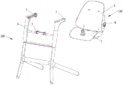
附图1为本实用新型的儿童餐椅的立体图;Accompanying drawing 1 is the perspective view of the children's dining chair of the present utility model;

附图2为本实用新型的儿童餐椅的侧视图;Accompanying drawing 2 is the side view of the children's dining chair of the present utility model;

附图3为本实用新型的儿童餐椅的主视图;Accompanying drawing 3 is the front view of the children's dining chair of the present utility model;

附图4为沿附图3中A-A向剖视结构示意图;Accompanying drawing 4 is along the A-A in accompanying drawing 3 cross-sectional structure schematic diagram;

附图5为本实用新型的儿童餐椅的侧视图;Accompanying drawing 5 is the side view of the children's dining chair of the present utility model;

附图6为沿附图5中B-B向剖视结构示意图;Accompanying drawing 6 is along B-B in accompanying drawing 5 sectional structure schematic diagram;

附图7、附图8均为座位组件从餐椅支架上拆解下后的示意图;Figure 7 and Figure 8 are schematic views of the seat assembly after being disassembled from the dining chair support;

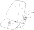
附图9为本实用新型的儿童餐椅上座位组件的立体图;9 is a perspective view of the seat assembly on the children's dining chair of the present invention;

附图10为本实用新型的儿童餐椅上座位组件中锁定座与靠背的拆解图;10 is a disassembled view of the locking seat and the backrest in the seat assembly of the children's dining chair of the present invention;

附图11为本实用新型的儿童餐椅的结构分解示意图;Accompanying drawing 11 is the structural decomposition schematic diagram of the children's dining chair of the present invention;

附图12为附图11中M处放大示意图;Accompanying drawing 12 is the enlarged schematic diagram of M in accompanying drawing 11;

附图13为附图11中N处放大示意图;Accompanying drawing 13 is the enlarged schematic diagram of N in accompanying drawing 11;

附图14为本实用新型的儿童餐椅的侧视图;14 is a side view of the children's dining chair of the present invention;

附图15为沿附图14中C-C向剖视结构示意图;Figure 15 is a schematic cross-sectional view of the structure along the C-C direction in Figure 14;

附图16为附图15中D处放大示意图;Accompanying drawing 16 is the enlarged schematic diagram at D in accompanying drawing 15;

附图17为附图15中靠背锁定件转为为解锁状态时的侧视图;Figure 17 is a side view of the backrest locking member in Figure 15 when it is turned into an unlocked state;

附图18为附图17中E处放大示意图;Figure 18 is an enlarged schematic view at E in Figure 17;

附图19为本实用新型的儿童餐椅的靠背角度调节示意图;19 is a schematic diagram of the backrest angle adjustment of the children's dining chair of the present invention;

附图20为本实用新型的儿童餐椅上座位组件的拆除步骤示意图;20 is a schematic diagram of the dismantling steps of the seat assembly on the children's dining chair of the present invention;

其中:100、座位组件;200、餐椅支架;101、转动轴;1、座板;2、靠背;2a、第一齿槽;3、侧支架;31、支架杆;31a、上支杆;31b、下支杆;32、扶手杆;33、后撑杆;34、脚踏板;35、下横杆;Among them: 100, seat assembly; 200, dining chair bracket; 101, rotating shaft; 1, seat plate; 2, backrest; 2a, first tooth slot; 3, side bracket; 31, bracket rod; 31a, upper support rod; 31b, lower strut; 32, handrail; 33, rear strut; 34, footrest; 35, lower crossbar;

4、支撑横杆;4a、限位部;5、导向滑块;5a、导槽;5b、套接部;6、滑轨;7、插接座;7a、插接口;7b、锁孔;7c、解锁按钮;8、锁定座;8a、收容腔;8b、盖板;81、锁舌;82、弹性件;9、锁定滑块;9a、锁定齿;10、弹簧;11、旋转轴。4. Supporting cross bar; 4a, limit part; 5, guide slider; 5a, guide groove; 5b, socket part; 6, slide rail; 7, socket; 7a, socket; 7b, lock hole; 7c, unlocking button; 8, locking seat; 8a, receiving cavity; 8b, cover plate; 81, locking tongue; 82, elastic piece; 9, locking slider; 9a, locking tooth; 10, spring; 11, rotating shaft.

具体实施方式Detailed ways

下面结合附图和具体实施例来对本实用新型的技术方案作进一步的阐述。The technical solutions of the present utility model will be further elaborated below in conjunction with the accompanying drawings and specific embodiments.

参见图1至图20所示,一种儿童餐椅,包括餐椅支架200和可拆卸地设置在餐椅支架200上的座位组件100,该座位组件100包括座板1与靠背2,座板1与靠背2之间活动地连接,且座板1与靠背2分别可拆卸地连接在餐椅支架200上。这样,当不使用该儿童餐椅时,或者在打包存储与运输时,可以将座位组件100从餐椅支架200上拆卸下来,并将座板1与靠背2相对折叠,减小座位组件100的尺寸,从而减小存储空间,方便运输与存放。1 to 20, a children's dining chair includes a dining chair bracket 200 and a seat assembly 100 detachably arranged on the dining chair bracket 200, the seat assembly 100 includes a seat plate 1 and a backrest 2, the seat plate 1 and the backrest 2 are movably connected, and the seat plate 1 and the backrest 2 are respectively detachably connected to the dining chair bracket 200 . In this way, when the children's high chair is not in use, or when packing, storing and transporting, the seat assembly 100 can be disassembled from the high chair support 200, and the seat panel 1 and the backrest 2 can be folded relative to each other, thereby reducing the size of the seat assembly 100. size, thereby reducing storage space and facilitating transportation and storage.

具体地,餐椅支架200至少具有分设于左右两侧的两个侧支架3,以及设于两侧侧支架3之间的支撑横杆4,座位组件100沿左右方向位于两个侧支架3之间,靠背2的左右两侧侧部分别与对应侧的侧支架3之间可拆卸地连接,座板1可拆卸地连接在支撑横杆4上。Specifically, the dining chair bracket 200 has at least two side brackets 3 arranged on the left and right sides, and a support cross bar 4 arranged between the two side brackets 3 , and the seat assembly 100 is located between the two side brackets 3 along the left-right direction. During the time, the left and right side parts of the backrest 2 are detachably connected to the side brackets 3 on the corresponding side respectively, and the seat plate 1 is detachably connected to the support cross bar 4 .

参见图1至8所示,侧支架3包括沿上下方向延伸的支架杆31、位于支架杆31上部且沿前后方向延伸的扶手杆32,靠背2的左右两侧部可拆卸地连接在对应侧扶手杆32的后部。此处,支架杆31包括沿上下方向可相对滑动伸缩的上支杆31a与下支杆31b,扶手杆32自上支杆31a的上部向后延伸;两侧的下支杆31b之间还固设有下横杆35,下支杆31b上还连接有向后并向下倾斜延伸的后撑杆33,使得餐椅支架200稳定地撑立于地面。支撑横杆4设于两侧支架杆31之间,此处具体为设于两侧上支杆31a之间,两侧上支杆31a的下部之间还设置有脚踏板34,以提供坐立在座板1上的儿童脚部支撑。1 to 8 , the side bracket 3 includes a bracket bar 31 extending in the up-down direction, a handrail bar 32 located on the upper part of the bracket bar 31 and extending in the front-rear direction, and the left and right sides of the backrest 2 are detachably connected to the corresponding side The rear of the grab bar 32. Here, the support rod 31 includes an upper support rod 31a and a lower support rod 31b that can be relatively slidably telescopic in the up-down direction. The handrail rod 32 extends backward from the upper part of the upper support rod 31a; the lower support rods 31b on both sides are also fixed between A lower cross bar 35 is provided, and the lower support bar 31b is also connected with a rear support bar 33 extending backward and inclined downward, so that the dining chair bracket 200 is stably supported on the ground. The support cross bar 4 is arranged between the support bars 31 on both sides, and here is specifically arranged between the upper struts 31a on both sides, and a footrest 34 is also arranged between the lower parts of the upper struts 31a on both sides to provide seating A child's foot support standing on the seat plate 1.

参见各附图所示,本实施例中,座位组件100中,座板1的后部与靠背2的下部通过转动轴101转动地连接,将座位组件100从餐椅支架200上拆卸下来后,可将座板1与靠背2相对转动收折予以存放。Referring to the drawings, in the present embodiment, in the seat assembly 100, the rear part of the seat plate 1 and the lower part of the backrest 2 are rotatably connected through the rotating shaft 101. After the seat assembly 100 is disassembled from the dining chair bracket 200, The seat plate 1 and the backrest 2 can be rotated and folded relative to each other for storage.

本实施例中,靠背2能够沿上下方向相对运动地连接至餐椅支架200上或者自餐椅支架200上拆离地设置,座板1既能够沿前后方向运动又能够相对转动地与餐椅支架200可拆卸地连接,这样座位组件100只需要通过靠背2与侧支架3连接,以及座板1与支撑横杆4的连接,即可稳定地安装在餐椅支架200上。在拆卸时,将靠背2向上提拉拔出时,座板1相对支撑横杆4微幅转动而便于靠背2与侧支架3脱开连接,随后再将座板1与支撑横杆4相互拆离,即可完成整个座位组件100在餐椅支架200上的拆除,十分方便。In this embodiment, the backrest 2 can be connected to or detached from the dining chair support 200 so as to be relatively movable in the up-down direction. The bracket 200 is detachably connected, so that the seat assembly 100 can be stably installed on the dining chair bracket 200 only through the connection between the backrest 2 and the side bracket 3 and the connection between the seat plate 1 and the support cross bar 4 . When disassembling, when the backrest 2 is pulled up and pulled out, the seat plate 1 rotates slightly relative to the support cross bar 4 to facilitate the disconnection of the backrest 2 and the side bracket 3, and then the seat plate 1 and the support cross bar 4 are disassembled from each other. It is very convenient to remove the entire seat assembly 100 from the dining chair support 200.

参见图7至图13所示,各侧的侧支架3上设有插接座7,靠背2的左右各侧部上均设有与插接座7项配合的锁定座8,锁定座8与插接座7之间沿上下方向可相对插拔地连接。具体地,此处,插接座7上设有插接口7a,锁定座8能够自上向下地插入至插接口7a中,插接座7与锁定座8之间还设有用于将两者相对锁定的插接锁定件。Referring to FIGS. 7 to 13 , the side brackets 3 on each side are provided with plug sockets 7 , and the left and right sides of the backrest 2 are provided with locking sockets 8 that cooperate with the socket sockets 7 . The sockets 7 are connected in a relatively pluggable and unpluggable manner along the up-down direction. Specifically, here, the socket 7 is provided with a socket 7a, and the locking socket 8 can be inserted into the socket 7a from top to bottom. Locked plug lock.

在这里,参见图8、图11及图13所示,该插接锁定件包括沿左右方向滑动地设置在锁定座8上的锁舌81、提供锁舌81沿滑动方向向外运动所需弹性力的弹性件82,此处弹性件82为弹簧,锁定座8上具有与插接口7a相配合的插接部,该插接部具有收容腔8a,以及盖设在收容腔8a口部上的盖板8b,弹簧82与锁舌81均安装于收容腔8a中。插接座7上设有用于供锁舌81对应配合地插入的锁孔7b,当锁定座8的插接部对应插设在插接口7a中时,锁舌81在弹簧82的作用下向外伸出并插设在锁孔7b中,使得插接锁定件保持锁定。Here, as shown in FIGS. 8 , 11 and 13 , the plug-in locking member includes a locking tongue 81 slidably arranged on the locking base 8 along the left-right direction, and provides the required elasticity for the locking tongue 81 to move outward along the sliding direction. The elastic member 82 of the force, here the elastic member 82 is a spring, the locking seat 8 has a plug-in part matched with the plug-in port 7a; The cover plate 8b, the spring 82 and the locking tongue 81 are all installed in the receiving cavity 8a. The socket 7 is provided with a lock hole 7b for the lock tongue 81 to be inserted correspondingly. When the plug portion of the lock socket 8 is inserted into the socket 7a correspondingly, the lock tongue 81 is under the action of the spring 82. It is protruded and inserted into the lock hole 7b, so that the plug-in lock is kept locked.

靠背2或侧支架3上还设有用于对插接锁定件解锁的解锁操作件,此处,该解锁操作件为沿上下方向滑动地设于插接座7上的解锁按钮7c,参见图11、图14至图18所示,解锁按钮7c的解锁操作端位于插接座7的底部,如此,在向上推动解锁按钮7c时,解锁按钮7c顶推锁舌81使其回退而使得插接锁定件解锁,从而可将锁定座8从插接座7上拔出。这样设置更便于用户的日常使用,且不会因为日常的误碰触操作而导致插接锁定件解锁。The backrest 2 or the side bracket 3 is also provided with an unlocking operation member for unlocking the plug-in locking member. Here, the unlocking operation member is an unlocking button 7c provided on the plug-in base 7 slidably in the up-down direction, see FIG. 11 14 to 18, the unlocking operation end of the unlocking button 7c is located at the bottom of the socket 7, so that when the unlocking button 7c is pushed up, the unlocking button 7c pushes the locking tongue 81 back to make the plug The locking element is unlocked, so that the locking socket 8 can be pulled out from the socket socket 7 . This setting is more convenient for the user's daily use, and the plug-in lock will not be unlocked due to daily mis-touch operations.

参见图10至图18所示,锁定座8绕左右方向延伸的旋转轴11转动地连接在靠背2的侧部上,这样可方便地调整靠背2的角度,使得座位组件100可提供不同坐姿的坐立支撑。靠背2与锁定座8之间还设有用于将两者相对锁定的靠背角度锁定件。10 to 18 , the locking seat 8 is rotatably connected to the side of the backrest 2 around the rotating shaft 11 extending in the left-right direction, so that the angle of the backrest 2 can be easily adjusted, so that the seat assembly 100 can provide different sitting postures. Sit support. Between the backrest 2 and the locking seat 8, there is also a backrest angle lock for locking the two relative to each other.

具体地,参见图13、图15至图18所示,该靠背锁定件包括设于靠背2上的多个第一齿槽2a、设于锁定座8上的多个第二齿槽(图中未示出),以及沿旋转轴11的轴向滑动地设于锁定座8与靠背2之间的锁定滑块9,锁定滑块9的外侧周部上设有多个锁定齿9a,锁定座8与锁定滑块9之间还设置有弹簧10。该靠背锁定件具有锁定状态与解锁状态,当靠背锁定组件处于锁定状态时,锁定齿9a同时插设在对应的第一齿槽2a与第二齿槽中,如图16所示;当靠背锁定组件处于解锁状态时,锁定齿9a完全脱离第二齿槽而仅插设在第一齿槽2a中,如图18所示。当然,也可以将弹簧10设于靠背2与锁定滑块9之间,使得靠背锁定组件解锁状态下仅插设在第二齿槽中。靠背2上还设有用于将上述靠背锁定件解锁的靠背调节件(图中未示出)。Specifically, as shown in FIGS. 13 , 15 to 18 , the backrest locking member includes a plurality of first tooth grooves 2 a provided on the backrest 2 and a plurality of second tooth grooves provided on the locking seat 8 (in the figure (not shown), and a locking slider 9 slidably provided between the locking seat 8 and the backrest 2 along the axial direction of the rotating shaft 11, the outer peripheral portion of the locking slider 9 is provided with a plurality of locking teeth 9a, the locking seat A spring 10 is also arranged between 8 and the locking slider 9 . The backrest locking member has a locked state and an unlocked state. When the backrest locking assembly is in the locked state, the locking teeth 9a are simultaneously inserted into the corresponding first tooth grooves 2a and the second tooth grooves, as shown in Figure 16; when the backrest is locked When the assembly is in the unlocked state, the locking teeth 9a are completely disengaged from the second tooth slot and only inserted into the first tooth slot 2a, as shown in FIG. 18 . Of course, the spring 10 can also be arranged between the backrest 2 and the locking slider 9, so that the backrest locking assembly is only inserted in the second tooth slot in the unlocked state. The backrest 2 is also provided with a backrest adjusting member (not shown in the figure) for unlocking the above-mentioned backrest locking member.

参见图3至图6,以及图11、图12所示,支撑横杆4上设置有导向滑块5,导向滑块5绕左右方向延伸的转动中心线转动地设置在支撑横杆4上,座板1与导向滑块5之间沿前后方向相对滑动地配合连接。此处,支撑横杆4的轴心线沿左右方向延伸,导向滑块5绕支撑横杆4的轴心线转动地设置。参图12所示,导向滑块5包括转动地套设在支撑横杆4上的套接部5b,其上还设有沿前后方向延伸的导槽5a,该导槽5a的横截面呈C型,亦即该导槽5a在垂直于其导向方向的截面上投影呈C字型。座板1的底部设置有能够与导槽5a相互滑动配合的滑轨6,且该座板1能够在向前滑动时自导向滑块5的前部脱开与导向滑块5之间的配合连接,以使得在靠背2与侧支架3相互拆离后向前滑动座板1即可将座板1与支撑横杆4拆离。支撑横杆4与导向滑块5之间还设有用于对导向滑块5的转动角度予以限位的角度限位结构,该角度限位结构包括设于支撑横杆4上的限位部4a,导向滑块5的部分位于该限位部4a中,这样不仅可保证在座位组件100拆卸与靠背角度调整的过程中,座板1能够相对支撑横杆4作适应性的角度调整,又能够进一步地保证座板1与支撑横杆4的连接可靠性。Referring to Figures 3 to 6, as well as Figures 11 and 12, the support cross bar 4 is provided with a guide slider 5, and the guide slider 5 is rotatably arranged on the support cross bar 4 around the rotation center line extending in the left-right direction, The seat plate 1 and the guide sliding block 5 are connected in a relatively sliding manner along the front-rear direction. Here, the axis line of the support cross bar 4 extends in the left-right direction, and the guide slider 5 is rotatably provided around the axis line of the support cross bar 4 . Referring to Fig. 12, the guide slider 5 includes a socket portion 5b rotatably sleeved on the support crossbar 4, and a guide groove 5a extending in the front-rear direction is also provided on the guide groove 5a, and the cross-section of the guide groove 5a is C. That is to say, the guide groove 5a is projected in a C-shape on a section perpendicular to its guiding direction. The bottom of the seat plate 1 is provided with a slide rail 6 that can slide and cooperate with the guide groove 5a, and the seat plate 1 can be disengaged from the front of the guide slider 5 when sliding forward. It is connected so that after the backrest 2 and the side bracket 3 are detached from each other, the seat panel 1 can be detached from the support cross bar 4 by sliding the seat panel 1 forward. An angle limit structure for limiting the rotation angle of the guide slider 5 is also provided between the support cross bar 4 and the guide slider 5 , and the angle limit structure includes a limit portion 4 a arranged on the support cross bar 4 . , the part of the guide slider 5 is located in the limiting portion 4a, which not only ensures that during the disassembly of the seat assembly 100 and the adjustment of the angle of the backrest, the seat plate 1 can be adjusted in an adaptive angle relative to the supporting cross bar 4, but also can be adjusted. This further ensures the reliability of the connection between the seat plate 1 and the support cross bar 4 .

综上,该儿童餐椅在使用的过程中,座板1连接在支撑横杆4上并与导向滑块5配合连接,靠背2的左右两侧部分别插接固定在两侧的侧支架3上。使用的过程中可通过操作靠背调节件来解锁靠背锁定件,并转动靠背2,使得靠背2的角度予以调整,座板1随靠背2的转动有适应性转动,使得整个座位组件100的坐姿状态发生调整,如图19所示。To sum up, in the process of using the children's dining chair, the seat plate 1 is connected to the support cross bar 4 and is connected with the guide slider 5, and the left and right sides of the backrest 2 are respectively inserted and fixed to the side brackets 3 on both sides. superior. During use, the backrest locking member can be unlocked by operating the backrest adjusting member, and the backrest 2 can be rotated, so that the angle of the backrest 2 can be adjusted, and the seat plate 1 can be adapted to rotate with the rotation of the backrest 2, so that the sitting posture state of the entire seat assembly 100 is achieved. An adjustment occurs, as shown in Figure 19.

当需要将座位组件100从餐椅支架200上拆卸下来时,参见图20所示,按压两侧的解锁按钮7c将两侧的插接锁定件解锁,然后向上拉动靠背2,使得锁定座8从插接座7中脱开,完成靠背2与侧支架3之间的拆除;随后向前推动整个座位组件100,使得座板1相对支撑横杆4向前运动,直至从滑轨6从导向滑块5的前部脱开配合,座板1也从支撑横杆4上拆除。接着再将餐椅支架200与座位组件100分别折叠打包即可,非常的简单,易于操作。When the seat assembly 100 needs to be disassembled from the dining chair support 200, as shown in FIG. 20, press the unlocking buttons 7c on both sides to unlock the plug-in locking pieces on both sides, and then pull up the backrest 2, so that the locking seat 8 is released from the Then, the entire seat assembly 100 is pushed forward, so that the seat plate 1 moves forward relative to the support cross bar 4, until the sliding rail 6 slides from the guide rail 6 forward. The front of the block 5 is disengaged and the seat plate 1 is also removed from the support rail 4 . Then, the dining chair bracket 200 and the seat assembly 100 can be folded and packaged separately, which is very simple and easy to operate.

上述实施例只为说明本实用新型的技术构思及特点,其目的在于让熟悉此项技术的人士能够了解本实用新型的内容并据以实施,并不能以此限制本实用新型的保护范围。凡根据本实用新型精神实质所作的等效变化或修饰,都应涵盖在本实用新型的保护范围之内。The above-mentioned embodiments are only to illustrate the technical concept and characteristics of the present invention, and the purpose thereof is to enable those who are familiar with the technology to understand the content of the present invention and implement accordingly, and cannot limit the protection scope of the present invention with this. All equivalent changes or modifications made according to the spirit of the present invention shall be included within the protection scope of the present invention.

Claims (17)

1.一种儿童餐椅,包括餐椅支架和可拆卸地设置在所述餐椅支架上的座位组件,其特征在于:所述座位组件包括座板与靠背,所述座板与所述靠背之间活动地连接,且所述座板与所述靠背分别可拆卸地连接在所述餐椅支架上。1. A children's dining chair, comprising a dining chair support and a seat assembly detachably arranged on the dining chair support, wherein the seat assembly comprises a seat plate and a backrest, the seat plate and the backrest They are movably connected therebetween, and the seat plate and the backrest are respectively detachably connected to the dining chair support. 2.根据权利要求1所述的儿童餐椅,其特征在于:所述座板的后部与所述靠背的下部转动地连接。2 . The high chair of claim 1 , wherein the rear portion of the seat plate is rotatably connected to the lower portion of the backrest. 3 . 3.根据权利要求2所述的儿童餐椅,其特征在于:所述靠背能够连接至所述餐椅支架上或自所述餐椅支架上拆离地设置,所述座板既能够沿前后方向滑动又能够相对转动地与所述餐椅支架可拆卸连接。3 . The children's dining chair according to claim 2 , wherein the backrest can be connected to or detached from the dining chair support, and the seat plate can be arranged along the front and rear. 4 . The direction sliding can be detachably connected with the dining chair bracket in a relatively rotatable manner. 4.根据权利要求3所述的儿童餐椅,其特征在于:所述餐椅支架至少具有分设于左右两侧的两个侧支架,所述座位组件沿左右方向位于两个所述侧支架之间,所述侧支架上设有插接座,所述靠背的左右各侧部上均设有与所述插接座相配合的锁定座,所述锁定座与所述插接座之间可相对插拔地连接。4 . The children's dining chair according to claim 3 , wherein the dining chair bracket has at least two side brackets disposed on the left and right sides, and the seat assembly is located between the two side brackets along the left-right direction. 5 . There are plug sockets on the side brackets, and locking sockets matched with the socket sockets are provided on the left and right side parts of the backrest. Relatively plug-in connection. 5.根据权利要求4所述的儿童餐椅,其特征在于:所述插接座上设有插接口,所述锁定座能够自上向下地插入至所述插接口中,所述插接座与所述锁定座之间还设有用于将两者相对锁定的插接锁定件。5. The children's dining chair according to claim 4, wherein the plug socket is provided with a socket port, the locking socket can be inserted into the socket port from top to bottom, and the socket socket A plug-in locking piece for locking the two relative to each other is also arranged between the locking base and the locking seat. 6.根据权利要求5所述的儿童餐椅,其特征在于:所述插接锁定件包括沿左右方向滑动地设于所述锁定座上的锁舌、提供所述锁舌沿滑动方向向外运动所需弹性力的弹性件,所述插接座上设有用于供所述锁舌对应配合地插入的锁孔,所述靠背或所述侧支架上还设有用于对所述插接锁定件解锁的解锁操作件。6 . The high chair of claim 5 , wherein the plug-in locking member comprises a lock tongue slidably provided on the locking seat along the left-right direction, and the lock tongue is provided to slide outward in the sliding direction. 7 . An elastic piece with elastic force required for movement, the socket seat is provided with a lock hole for the lock tongue to be inserted correspondingly, and the backrest or the side bracket is also provided with a lock for the socket connection The unlocking operating piece for the unlocking of the piece. 7.根据权利要求6所述的儿童餐椅,其特征在于:所述解锁操作件为沿上下方向滑动地设于所述插接座上的解锁按钮,且所述解锁按钮的解锁操作端位于所述插接座的底部。7 . The high chair for children according to claim 6 , wherein the unlocking operation member is an unlocking button that is slidably arranged on the socket seat in the up-down direction, and the unlocking operation end of the unlocking button is located at the the bottom of the socket. 8.根据权利要求4所述的儿童餐椅,其特征在于:所述锁定座绕左右方向延伸的旋转轴转动地连接在所述靠背上,所述靠背与所述锁定座之间还设有用于将两者相对锁定的靠背角度锁定件。8 . The high chair for children according to claim 4 , wherein the locking seat is rotatably connected to the backrest around a rotation axis extending in the left-right direction, and there is a function between the backrest and the locking seat. 9 . The backrest angle lock for locking the two relative to each other. 9.根据权利要求8所述的儿童餐椅,其特征在于:所述靠背锁定件包括设于所述靠背上的多个第一齿槽、设于所述锁定座上的多个第二齿槽,以及沿所述旋转轴的轴向滑动地设于所述锁定座与所述靠背之间的锁定滑块,所述锁定滑块的外侧周部上设有多个锁定齿,所述靠背锁定件具有锁定状态与解锁状态,当所述靠背锁定件处于锁定状态时,所述锁定齿同时插设在对应的所述第一齿槽与第二齿槽中;当所述靠背锁定件处于解锁状态时,所述锁定齿完全地脱离所述第一齿槽或者完全地脱离所述第二齿槽,所述靠背上还设有用于将所述靠背锁定件解锁的靠背调节件。9 . The high chair of claim 8 , wherein the backrest locking member comprises a plurality of first tooth grooves provided on the backrest and a plurality of second teeth provided on the locking seat. 10 . a slot, and a locking slider slidably provided between the locking seat and the backrest along the axial direction of the rotating shaft, a plurality of locking teeth are provided on the outer peripheral portion of the locking slider, the backrest The locking piece has a locking state and an unlocking state. When the backrest locking piece is in the locking state, the locking teeth are simultaneously inserted into the corresponding first tooth groove and the second tooth groove; when the backrest locking piece is in the locking state In the unlocked state, the locking teeth are completely disengaged from the first tooth slot or completely disengaged from the second tooth slot, and a backrest adjusting member for unlocking the backrest locking member is further provided on the backrest. 10.根据权利要求4至9任一项所述的儿童餐椅,其特征在于:所述餐椅支架还包括设于两侧所述侧支架之间的支撑横杆,所述支撑横杆上设置有导向滑块,所述导向滑块绕左右方向延伸的转动中心线转动地连接在所述支撑横杆上,所述座板与所述导向滑块之间沿前后方向相互滑动地配合连接。10. The children's dining chair according to any one of claims 4 to 9, wherein the dining chair bracket further comprises a support crossbar disposed between the side brackets on both sides, and the support crossbar is A guide slider is provided, the guide slider is rotatably connected to the support crossbar around the rotation center line extending in the left-right direction, and the seat plate and the guide slider are slidably connected to each other along the front-rear direction. . 11.根据权利要求10所述的儿童餐椅,其特征在于:所述导向滑块上具有沿前后方向延伸且横截面呈C型的导槽,所述座板的底部设置有能够与所述导槽相互滑动配合的滑轨。11. The children's dining chair according to claim 10, characterized in that: the guide slider has a guide groove extending in the front-rear direction and having a C-shaped cross-section, and the bottom of the seat plate is provided with a Slide rails with guide grooves slidingly matched with each other. 12.根据权利要求10所述的儿童餐椅,其特征在于:所述座板能够在向前滑动时自所述导向滑块的前部脱开与所述导向滑块之间的配合连接。12 . The high chair for children according to claim 10 , wherein the seat plate can be disengaged from the front portion of the guide slider from the matching connection with the guide slider when the seat plate is slid forward. 13 . 13.根据权利要求10所述的儿童餐椅,其特征在于:所述支撑横杆的轴心线沿左右方向延伸,所述导向滑块绕所述支撑横杆的轴心线转动地设置,所述支撑横杆与所述导向滑块之间还设有用于对所述导向滑块的转动角度予以限位的角度限位结构。13 . The children's dining chair according to claim 10 , wherein the axis line of the support cross bar extends along the left-right direction, and the guide slider is rotatably arranged around the axis line of the support cross bar, 13 . An angle limiting structure for limiting the rotation angle of the guide sliding block is further provided between the support cross bar and the guide sliding block. 14.根据权利要求1至3任一项所述的儿童餐椅,其特征在于:所述餐椅支架至少具有分设于左右两侧的两个侧支架,以及设于两侧所述侧支架之间的支撑横杆,所述座位组件沿左右方向位于两个所述侧支架之间,所述靠背的左右两个侧部分别与对应侧的所述侧支架之间可拆卸地连接,所述座板可滑动地设置在所述支撑横杆上,并且可从所述支撑横杆上拆卸。14. The children's dining chair according to any one of claims 1 to 3, wherein the dining chair bracket has at least two side brackets arranged on the left and right sides, and one of the side brackets arranged on both sides. The seat assembly is located between the two side brackets in the left-right direction, and the left and right side parts of the backrest are respectively detachably connected with the side brackets on the corresponding side. A seat plate is slidably disposed on and detachable from the support rail. 15.根据权利要求14所述的儿童餐椅,其特征在于:所述侧支架包括沿上下方向延伸的支架杆、位于所述支架杆的上部且沿前后方向延伸的扶手杆,所述靠背的侧部可拆卸地连接在所述扶手杆的后部。15. The children's dining chair according to claim 14, wherein the side bracket comprises a bracket rod extending in an up-down direction, a handle bar located on the upper part of the bracket rod and extending in the front-rear direction, and the backrest A side portion is removably attached to the rear of the grab bar. 16.根据权利要求15所述的儿童餐椅,其特征在于:所述支撑横杆设于两侧的所述支架杆之间,两侧的所述支架杆之间还设置有脚踏板,所述脚踏板位于所述支撑横杆的下方。16. The children's dining chair according to claim 15, characterized in that: the support bars are arranged between the bracket bars on both sides, and footrests are also arranged between the bracket bars on both sides, The footrest is located below the support rail. 17.根据权利要求15所述的儿童餐椅,其特征在于:所述支架杆包括沿上下方向可相对滑动伸缩的上支杆与下支杆,所述扶手杆自所述上支杆的上部向后延伸,所述下支杆上还连接有向后并向下倾斜延伸的后撑杆。17 . The children's dining chair according to claim 15 , wherein the support rod comprises an upper support rod and a lower support rod that are relatively slidable and retractable along the up-down direction, and the armrest rod is formed from the upper part of the upper support rod. 18 . Extending backward, the lower strut is also connected with a rear strut extending backward and obliquely downward.
CN201822056683.9U 2018-12-07 2018-12-07 Children dining chair Withdrawn - After Issue CN209898871U (en)

Priority Applications (1)

Application Number Priority Date Filing Date Title
CN201822056683.9U CN209898871U (en) 2018-12-07 2018-12-07 Children dining chair

Applications Claiming Priority (1)

Application Number Priority Date Filing Date Title
CN201822056683.9U CN209898871U (en) 2018-12-07 2018-12-07 Children dining chair

Publications (1)

Publication Number Publication Date
CN209898871U true CN209898871U (en) 2020-01-07

Family

ID=69026075

Family Applications (1)

Application Number Title Priority Date Filing Date
CN201822056683.9U Withdrawn - After Issue CN209898871U (en) 2018-12-07 2018-12-07 Children dining chair

Country Status (1)

Country Link
CN (1) CN209898871U (en)

Cited By (1)

* Cited by examiner, † Cited by third party
Publication number Priority date Publication date Assignee Title
CN109567481A (en) * 2018-12-07 2019-04-05 好孩子儿童用品有限公司 Children dinning chair

Cited By (2)

* Cited by examiner, † Cited by third party
Publication number Priority date Publication date Assignee Title
CN109567481A (en) * 2018-12-07 2019-04-05 好孩子儿童用品有限公司 Children dinning chair
CN109567481B (en) * 2018-12-07 2023-11-24 好孩子儿童用品有限公司 Dining chair for children

Similar Documents

Publication Publication Date Title
KR102165079B1 (en) stroller
CN211242450U (en) Folding chair
US11622632B2 (en) Feature high chair
CN104085434B (en) The seat pocket of children trolley
JPH0775984B2 (en) Stroller reclining or lodging mechanism
CN111907578A (en) Multi-seat infant stroller
CN111280946A (en) Children dining chair
CN109567481B (en) Dining chair for children
US20140159437A1 (en) Outdoor reclining chair
CN120270319A (en) Barrows
CN206534415U (en) Children dinning chair
TW202608357A (en) High chair
JP6397522B2 (en) Frame structure, wheelchair, stroller & chair
CN205144092U (en) Novel children's high chair
CN116176681B (en) Strollers
JP2011172857A (en) Chair
CN219613474U (en) Foldable children seat
CN209898872U (en) Children's chair
CN118285647A (en) A multifunctional children's dining chair
CN111588225A (en) Children dining chair
CN208676777U (en) children's dining chair
WO2019242063A1 (en) Folding electric wheelchair
CN221469449U (en) Folding chair
CN224013673U (en) Barrows
CN209058527U (en) Multifunctional dining chair

Legal Events

Date Code Title Description
GR01 Patent grant
GR01 Patent grant
AV01 Patent right actively abandoned

Granted publication date: 20200107

Effective date of abandoning: 20231124

AV01 Patent right actively abandoned

Granted publication date: 20200107

Effective date of abandoning: 20231124