CN209898631U - Movable bed table for rehabilitation bed - Google Patents
Movable bed table for rehabilitation bed Download PDFInfo
- Publication number
- CN209898631U CN209898631U CN201821725863.5U CN201821725863U CN209898631U CN 209898631 U CN209898631 U CN 209898631U CN 201821725863 U CN201821725863 U CN 201821725863U CN 209898631 U CN209898631 U CN 209898631U
- Authority
- CN
- China
- Prior art keywords
- bed
- fixedly connected
- movable
- wall
- slot
- Prior art date
- Legal status (The legal status is an assumption and is not a legal conclusion. Google has not performed a legal analysis and makes no representation as to the accuracy of the status listed.)
- Expired - Fee Related
Links
Images
Landscapes
- Accommodation For Nursing Or Treatment Tables (AREA)
Abstract
Description
技术领域technical field
本实用新型涉及医疗用品技术领域,具体为一种用于康复床的活动床上桌。The utility model relates to the technical field of medical supplies, in particular to a movable bed table used for a rehabilitation bed.
背景技术Background technique
目前,随着社会的医疗的发展与进步,医疗康复护理越来越受关注,因为医疗护理对于病人的康复很重要,如果没有一个好的康复护理,这样很可能会使病人的康复效果降低,甚至可能会让病人的病情加重,尤其是骨科护理更加需要有个良好的康复护理。骨科病人在进行骨科手术后往往需要卧床静养一段时间,静养时由于病人大多不能擅自移动身体,因此当需要拿取物品和用餐时会非常不便,虽然市面上有懒人桌等用品,但由于结构设计的原因,其功能比较单一,使用起来不是很方便,并且不能随意移动位置和调节高度,灵活性差。At present, with the development and progress of medical care in society, medical rehabilitation care has attracted more and more attention, because medical care is very important for the recovery of patients. If there is no good rehabilitation care, the rehabilitation effect of patients may be reduced. It may even make the patient's condition worse, especially orthopedic care needs a good rehabilitation care. Orthopedic patients often need to rest in bed for a period of time after orthopedic surgery. Most of the patients cannot move their bodies without authorization, so it is very inconvenient when they need to take items and eat. Although there are lazy tables and other products on the market, due to the structure The reason for the design is that its function is relatively simple, it is not very convenient to use, and it cannot move the position and adjust the height at will, and the flexibility is poor.
实用新型内容Utility model content
本实用新型解决的技术问题在于克服现有技术的懒人桌结构简单,使用不便,不能随意移动,灵活性差的缺陷,提供一种用于康复床的活动床上桌。所述一种用于康复床的活动床上桌具有使用方便,可随意折叠、移动,高度可调,灵活性好,稳定性高等特点。The technical problem solved by the utility model is to overcome the defects of the prior art lazy table with simple structure, inconvenient use, inability to move at will, and poor flexibility, and to provide a movable bed table for a rehabilitation bed. The movable bed table for a rehabilitation bed has the characteristics of convenient use, free folding and movement, adjustable height, good flexibility and high stability.
为实现上述目的,本实用新型提供如下技术方案:一种用于康复床的活动床上桌,包括床体,所述床体的底部两侧分别固定连接有一对床腿,一对所述床腿之间固定连接有导轨,所述床体的两侧侧壁均开设有活动槽,所述活动槽内插入有桌体,所述桌体的侧壁固定连接有把手,且所述桌体的顶部两侧均固定连接有固定管,所述固定管的管壁固定连接有定位管,所述定位管的内壁刻有内螺纹,且所述定位管通过内螺纹螺纹连接有螺栓,所述定位管的管内插入有活动杆,所述活动杆的杆身开设有若干个与螺栓相配合的定位孔,且所述活动杆的顶端开设有插槽,所述插槽内插入有活动块,所述活动块上开设有通孔,且所述活动块的通孔内插入有固定轴,所述固定轴贯穿插槽的两侧槽壁,且所述固定轴的两端均固定连接有挡块,所述活动块的顶部固定连接有桌面,所述桌面的内腔设置有板槽,所述板槽的中心设置有隔板,所述隔板的顶部和底部分别固定连接在板槽的内壁顶部和底部,所述板槽内插入有桌板,且所述板槽的外侧侧壁开设有滑槽,所述桌板靠近滑槽一侧的侧壁固定连接有滑杆,所述滑杆靠近隔板一侧,且所述滑杆穿过滑槽并延伸至板槽外,且所述滑杆的末端固定连接有滑块,所述桌板远离滑块的一端侧壁开设有弧形槽,其槽壁内固定连接有拉手,所述桌体的底部固定连接有轮架,所述轮架为U字形结构,其内壁固定连接有两根轮轴,两根所述轮轴的轴身均活动连接有滚轮。In order to achieve the above purpose, the present utility model provides the following technical solutions: a movable bed table for a rehabilitation bed, comprising a bed body, and a pair of bed legs are fixedly connected to both sides of the bottom of the bed body, respectively, and a pair of the bed legs Guide rails are fixedly connected between them, and movable grooves are opened on both side walls of the bed body, a table body is inserted into the movable grooves, the side walls of the table body are fixedly connected with handles, and the table body is Both sides of the top are fixedly connected with a fixed pipe, the pipe wall of the fixed pipe is fixedly connected with a positioning pipe, the inner wall of the positioning pipe is engraved with an internal thread, and the positioning pipe is threadedly connected with a bolt through the internal thread, and the positioning pipe is threaded. A movable rod is inserted into the tube of the pipe, the rod body of the movable rod is provided with a number of positioning holes matched with the bolts, and the top end of the movable rod is provided with a slot, and a movable block is inserted into the slot, so the The movable block is provided with a through hole, and a fixed shaft is inserted into the through hole of the movable block, the fixed shaft penetrates the groove walls on both sides of the slot, and both ends of the fixed shaft are fixedly connected with stoppers , the top of the movable block is fixedly connected with a tabletop, the inner cavity of the tabletop is provided with a plate groove, the center of the plate groove is provided with a partition, and the top and bottom of the partition are respectively fixed to the inner wall of the plate groove At the top and bottom, a table board is inserted into the board slot, and a chute is provided on the outer side wall of the board slot, and a side wall of the table board close to the chute is fixedly connected with a sliding rod, and the sliding rod Close to the side of the partition, and the sliding rod passes through the chute and extends out of the board groove, and the end of the sliding rod is fixedly connected with a slider, and the side wall of one end of the table plate away from the slider is provided with an arc. The groove, the groove wall is fixedly connected with a handle, the bottom of the table body is fixedly connected with a wheel frame, the wheel frame is a U-shaped structure, and its inner wall is fixedly connected with two wheel axles, and the axle bodies of the two wheel axles are both Active connections have scroll wheels.
优选的,所述把手上套设有硅胶套,硅胶套的内侧开设有四个弧形槽。Preferably, the handle is covered with a silicone sleeve, and the inner side of the silicone sleeve is provided with four arc-shaped grooves.
优选的,所述滚轮的数量有四个,其轮壁设置有一圈轮齿,所述导轨的顶部表面设置有若干个与轮齿相啮合的条齿。Preferably, the number of the rollers is four, the wheel wall is provided with a circle of gear teeth, and the top surface of the guide rail is provided with a plurality of rack teeth that mesh with the gear teeth.
优选的,所述滑块的直径大于滑槽的槽宽,所述滑杆的杆径小于滑槽的槽宽。Preferably, the diameter of the slider is larger than the slot width of the chute, and the rod diameter of the sliding rod is smaller than the slot width of the chute.
优选的,所述桌面有两块,其形状完全相同,且两块所述桌面的接触部分均固定连接有卡块。Preferably, the table top has two pieces with the same shape, and the contact parts of the two table tops are fixedly connected with a clamping block.
与现有技术相比,本实用新型的有益效果是:Compared with the prior art, the beneficial effects of the present utility model are:
1、操作简单,使用方便,灵活性强,可根据需要随意移动该床上桌的位置,并可调节其高度。1. The operation is simple, the use is convenient, and the flexibility is strong. The position of the bed table can be moved freely according to the needs, and its height can be adjusted.
2、可随时折叠桌面,从而减小该床上桌对康复床的占用面积,避免其影响病人的其他活动。2. The table top can be folded at any time, thereby reducing the occupation area of the bed table on the rehabilitation bed and preventing it from affecting other activities of the patient.
3、稳定性高,该床上桌在移动过程中不易发生晃动和颠簸。3. High stability, the bed table is not easy to shake and bump during the moving process.
附图说明Description of drawings
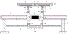
图1为本实用新型的整体结构示意图;Fig. 1 is the overall structure schematic diagram of the present utility model;
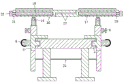
图2为图1的侧面结构示意图。FIG. 2 is a schematic side view of the structure of FIG. 1 .
图中标号:1床体、2床腿、3导轨、4活动槽、5桌体、6把手、7固定管、8定位管、9螺栓、10活动杆、11定位孔、12插槽、13活动块、14固定轴、15挡块、16桌面、17板槽、18隔板、19桌板、20滑槽、21滑杆、22滑块、23拉手、24轮架、25轮轴、26滚轮、27卡块。Labels in the figure: 1 bed body, 2 bed legs, 3 guide rails, 4 movable slots, 5 table bodies, 6 handles, 7 fixed tubes, 8 positioning tubes, 9 bolts, 10 movable rods, 11 positioning holes, 12 slots, 13 Active block, 14 fixed shaft, 15 block, 16 table top, 17 board slot, 18 partition board, 19 table board, 20 chute, 21 slide bar, 22 slider, 23 handle, 24 wheel frame, 25 wheel axle, 26 roller , 27 card blocks.
具体实施方式Detailed ways
下面将结合本实用新型实施例中的附图,对本实用新型实施例中的技术方案进行清楚、完整地描述,显然,所描述的实施例仅仅是本实用新型一部分实施例,而不是全部的实施例。基于本实用新型中的实施例,本领域普通技术人员在没有做出创造性劳动前提下所获得的所有其他实施例,都属于本实用新型保护的范围。The technical solutions in the embodiments of the present utility model will be clearly and completely described below with reference to the accompanying drawings in the embodiments of the present utility model. Obviously, the described embodiments are only a part of the embodiments of the present utility model, rather than all the implementations. example. Based on the embodiments of the present invention, all other embodiments obtained by those of ordinary skill in the art without creative work fall within the protection scope of the present invention.
请参阅图1-2,本实用新型提供一种技术方案:一种用于康复床的活动床上桌,包括床体1,床体1的底部两侧分别固定连接有一对床腿2,一对床腿2之间固定连接有导轨3,床体1的两侧侧壁均开设有活动槽4,活动槽4内插入有桌体5,桌体5的内壁设置有与活动槽4相配合的凸块,可提高桌体5的稳定性,防止其移动时发生晃动,桌体5的侧壁固定连接有把手6,把手6上套设有硅胶套,硅胶套的内侧开设有四个弧形槽,当人手握住把手6时四个手指可紧紧贴合在四个弧形槽内,从而可提高人手对把手6的握持,防止打滑,桌体5的顶部两侧均固定连接有固定管7,固定管7的管壁固定连接有定位管8,定位管8的内壁刻有内螺纹,且定位管8通过内螺纹螺纹连接有螺栓9,定位管8的管内插入有活动杆10,活动杆10的杆身开设有若干个与螺栓9相配合的定位孔11,且活动杆10的顶端开设有插槽12,插槽12内插入有活动块13,活动块13上开设有通孔,且活动块13的通孔内插入有固定轴14,固定轴14贯穿插槽12的两侧槽壁,且固定轴14的两端均固定连接有挡块15,活动块13的顶部固定连接有桌面16,桌面16有两块,其形状完全相同,且两块桌面16的接触部分均固定连接有卡块27,当两块桌面16呈水平放置时利用卡块27可起到卡位和固定的作用,防止桌面16受力后发生倾斜,桌面16的内腔设置有板槽17,板槽17的中心设置有隔板18,隔板18的顶部和底部分别固定连接在板槽17的内壁顶部和底部,板槽17内插入有桌板19,且板槽17的外侧侧壁开设有滑槽20,桌板19靠近滑槽20一侧的侧壁固定连接有滑杆21,滑杆21靠近隔板18一侧,且滑杆21穿过滑槽20并延伸至板槽17外,且滑杆21的末端固定连接有滑块22,滑块22的直径大于滑槽20的槽宽,滑杆21的杆径小于滑槽20的槽宽,利用滑杆21和滑块22可防止桌板19被整个抽出板槽17,桌板19远离滑块22的一端侧壁开设有弧形槽,其槽壁内固定连接有拉手23,桌体5的底部固定连接有轮架24,轮架24为U字形结构,其内壁固定连接有两根轮轴25,两根轮轴25的轴身均活动连接有滚轮26,滚轮26的数量有四个,其轮壁设置有一圈轮齿,导轨3的顶部表面设置有若干个与轮齿相啮合的条齿,利用条齿与轮齿之间的啮合作用可提高滚轮26旋转时的稳定性,从而防止桌体5在移动过程中发生晃动和颠簸。1-2, the present invention provides a technical solution: a movable bed table for a rehabilitation bed, comprising a bed body 1, and a pair of
工作原理:本实用新型在使用时,通过绕着固定轴14旋转活动块13,从而使其带动两块桌面16转动,直至两块桌面16呈水平放置,利用卡块27可对两块桌面16进行卡位和固定,以便将物品放置在桌面16上以方便病人取用,或者供病人用餐时摆放餐具和食品,当需要调节桌面16的高度时,将螺栓9抽出定位管8,并沿着固定管7上下移动活动杆10,待桌面16到达所需的高度位置时,再将螺栓9对准并旋入相应高度位置的定位孔11内,从而对桌面16的高度进行固定,握住拉手23可将桌板19从板槽17中抽出,从而可增大桌面16的宽度,以便扩大桌面16的可用范围,当需要移动该床上桌的位置时,握住把手6并带动桌体5使其沿着活动槽4左右移动,从而可根据需要调节桌面16的位置,以方便病人在不需要费力的情况下便能轻松使用,当不需要使用该床上桌时,可将桌体5移动至床体1的尾部,然后转动两块桌面16使其分离并呈垂直放置,从而可将两块桌面16分别收至床体1的两侧,以避免该床上桌占用康复床的面积而影响病人的其他活动。Working principle: When the utility model is in use, the movable block 13 is rotated around the fixed axis 14, so that it drives the two
尽管已经示出和描述了本实用新型的实施例,对于本领域的普通技术人员而言,可以理解在不脱离本实用新型的原理和精神的情况下可以对这些实施例进行多种变化、修改、替换和变型,本实用新型的范围由所附权利要求及其等同物限定。Although the embodiments of the present invention have been shown and described, it will be understood by those skilled in the art that various changes and modifications can be made to these embodiments without departing from the principles and spirit of the present invention , alternatives and modifications, the scope of the present invention is defined by the appended claims and their equivalents.
Claims (5)
Priority Applications (1)
| Application Number | Priority Date | Filing Date | Title |
|---|---|---|---|
| CN201821725863.5U CN209898631U (en) | 2018-10-24 | 2018-10-24 | Movable bed table for rehabilitation bed |
Applications Claiming Priority (1)
| Application Number | Priority Date | Filing Date | Title |
|---|---|---|---|
| CN201821725863.5U CN209898631U (en) | 2018-10-24 | 2018-10-24 | Movable bed table for rehabilitation bed |
Publications (1)
| Publication Number | Publication Date |
|---|---|
| CN209898631U true CN209898631U (en) | 2020-01-07 |
Family
ID=69027935
Family Applications (1)
| Application Number | Title | Priority Date | Filing Date |
|---|---|---|---|
| CN201821725863.5U Expired - Fee Related CN209898631U (en) | 2018-10-24 | 2018-10-24 | Movable bed table for rehabilitation bed |
Country Status (1)
| Country | Link |
|---|---|
| CN (1) | CN209898631U (en) |
Cited By (1)
| Publication number | Priority date | Publication date | Assignee | Title |
|---|---|---|---|---|
| CN116229809A (en) * | 2023-03-09 | 2023-06-06 | 中国人民解放军空军军医大学 | A teaching device for manipulative reduction of temporomandibular joint dislocation |
-
2018
- 2018-10-24 CN CN201821725863.5U patent/CN209898631U/en not_active Expired - Fee Related
Cited By (1)
| Publication number | Priority date | Publication date | Assignee | Title |
|---|---|---|---|---|
| CN116229809A (en) * | 2023-03-09 | 2023-06-06 | 中国人民解放军空军军医大学 | A teaching device for manipulative reduction of temporomandibular joint dislocation |
Similar Documents
| Publication | Publication Date | Title |
|---|---|---|
| CN109998832B (en) | Detachable movable medical sickbed capable of transferring patients quickly and safely | |
| CN211131836U (en) | An adjustable orthopedic joint hanger | |
| CN211244320U (en) | Medicine box for outpatient nursing of children | |
| CN106309043B (en) | A lathe integrated nursing device | |
| CN108403353A (en) | Operation trolley over invalid bed board | |
| CN205832058U (en) | A kind of internal medicine nursing bed | |
| CN202537810U (en) | Nursing sickbed | |
| CN206880795U (en) | A kind of sick bed for being easy to accompany and attend to | |
| CN211243750U (en) | Anesthesia Instrument Rack | |
| CN113069215A (en) | Liftable operation hook for hepatobiliary surgery | |
| CN217723993U (en) | PICC dressing change car | |
| CN113288625B (en) | Portable blood disease nursing bed with sterilization function | |
| CN214908859U (en) | Orthopedics backbone strutting arrangement | |
| CN215737604U (en) | A medical bedside table with a rotatable dining table board | |
| CN210872696U (en) | An improved treatment vehicle | |
| CN203524127U (en) | Dining table special for bedridden patient | |
| CN202620048U (en) | Medical nursing hospital bed | |
| CN211300853U (en) | Breathe internal medicine nursing cabinet | |
| CN114404180A (en) | Severe branch of academic or vocational study is with nursing handing-over device | |
| CN221730096U (en) | A convenient nursing bedside table | |
| CN223654109U (en) | A gynecological examination bed that is easy to disinfect and change dressings | |
| CN221243225U (en) | A medical human body transfer platform | |
| CN209790031U (en) | An operating room nursing bracket | |
| CN216417592U (en) | Telescopic quilt supporting frame | |
| CN220385181U (en) | A transport support for physical examination apparatus containing box |
Legal Events
| Date | Code | Title | Description |
|---|---|---|---|
| GR01 | Patent grant | ||
| GR01 | Patent grant | ||
| CF01 | Termination of patent right due to non-payment of annual fee |
Granted publication date: 20200107 Termination date: 20201024 |
|
| CF01 | Termination of patent right due to non-payment of annual fee |