CN209891706U - Pouring template for building construction - Google Patents
Pouring template for building construction Download PDFInfo
- Publication number
- CN209891706U CN209891706U CN201920488145.9U CN201920488145U CN209891706U CN 209891706 U CN209891706 U CN 209891706U CN 201920488145 U CN201920488145 U CN 201920488145U CN 209891706 U CN209891706 U CN 209891706U
- Authority
- CN
- China
- Prior art keywords
- panel
- base
- connecting block
- pouring template
- spout
- Prior art date
- Legal status (The legal status is an assumption and is not a legal conclusion. Google has not performed a legal analysis and makes no representation as to the accuracy of the status listed.)
- Expired - Fee Related
Links
- 238000009435 building construction Methods 0.000 title claims description 9
- 238000010276 construction Methods 0.000 claims abstract description 12
- 238000009415 formwork Methods 0.000 claims description 4
- 230000001105 regulatory effect Effects 0.000 claims 3
- 238000000034 method Methods 0.000 description 3
- XEEYBQQBJWHFJM-UHFFFAOYSA-N Iron Chemical compound [Fe] XEEYBQQBJWHFJM-UHFFFAOYSA-N 0.000 description 2
- 238000010586 diagram Methods 0.000 description 2
- 238000005266 casting Methods 0.000 description 1
- 229910052742 iron Inorganic materials 0.000 description 1
- 239000002023 wood Substances 0.000 description 1
Images
Landscapes
- Conveying And Assembling Of Building Elements In Situ (AREA)
Abstract
The utility model discloses a pouring template for construction, including panel and base, the panel is equipped with the fly leaf on the front, fly leaf and panel sliding connection, the fly leaf back is equipped with connecting block one, the panel back is equipped with connecting block two with a connecting block position department of correspondence, threaded connection has the regulation pole on the connecting block two, it rotates with one connecting block to adjust the one end that the pole is located the panel and is connected, it serves to be equipped with the commentaries on classics handle outside the panel to adjust the pole position, the panel bottom is equipped with the base, be equipped with the spout on the base, the panel passes through spout and base sliding connection, be equipped with the connecting plate of being connected with the panel in the spout, the one end of keeping away from the panel in the spout is equipped with positioning bolt, be equipped with the shoulder hole on the base, the. Compared with the prior art, the utility model the advantage lie in: simple structure, convenient drawing of patterns, convenient to use, repeatedly usable.
Description
Technical Field
The utility model relates to a building construction equipment technical field specifically indicates a casting mold board for construction.
Background
In concrete pouring construction, hammers and nails are added on wood and iron saws in the traditional method, the labor intensity is high, the operation is complicated, the labor and the time are wasted, the speed is low, and a template pouring process appears along with the technical progress. The pouring formwork is a temporary supporting structure, which is manufactured according to the design requirements, so that the concrete structure and the member are formed according to the specified position and geometric dimension, the correct position of the concrete structure and the member is kept, and the self weight of the building formwork and the external load acting on the building formwork are born. The method aims to ensure the quality and the construction safety of the concrete engineering, accelerate the construction progress and reduce the engineering cost. However, the existing pouring template has a complex structure and is not easy to demould, and the development and the use of the pouring template are restricted.
SUMMERY OF THE UTILITY MODEL
The to-be-solved technical problem of the utility model is that the tradition is pour template structure and functional problem, provides a simple structure, makes things convenient for drawing of patterns, convenient to use, repeatedly usable's a pouring template for construction.
In order to solve the technical problem, the utility model provides a technical scheme does: the utility model provides a pouring template for construction, includes panel and base, be equipped with the fly leaf on the panel openly, fly leaf and panel sliding connection, the fly leaf back is equipped with connecting block one, the panel back is equipped with connecting block two with a position department of correspondence of connecting block, threaded connection has the regulation pole on the connecting block two, the one end that the regulation pole is located the panel rotates with one connecting block to be connected, it serves to be equipped with the commentaries on classics handle outside the panel to adjust the pole position, the panel bottom is equipped with the base, be equipped with the spout on the base, the panel passes through spout and base sliding connection, be equipped with the connecting plate of being connected with the panel in the spout, the one end of keeping away from the panel in the spout is equipped with positioning bolt, be equipped with the shoulder hole on.
Compared with the prior art, the utility model the advantage lie in: according to the pouring template for building construction, the panel is connected with the base in a sliding manner, the adjusting rod is rotatably connected with one connecting block on the movable plate and is in threaded connection with the second connecting block on the panel, and the length of the adjusting rod in the panel can be adjusted by rotating the adjusting rod, so that the adjusting rod pushes the panel to slide on the base, the panel is conveniently separated from a concrete wall, and demolding is more convenient; the left side and the right side of the panel are respectively provided with a first connecting groove and a second connecting groove, so that the panels can be combined conveniently.
As an improvement, the opening directions of the first connecting groove and the second connecting groove are opposite.
As an improvement, the movable plates are at least 4 and are uniformly distributed on the front surface of the panel.
As a refinement, the stepped hole has 2 rows on the base, and each row has at least 4.
As the improvement, there are 2 spouts, lie in the left and right sides of base up end respectively.
Drawings
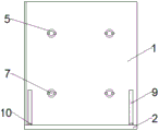
Fig. 1 is the utility model discloses a front structure schematic diagram of pouring template for construction.
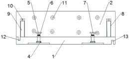
Fig. 2 is the utility model relates to a back structure schematic diagram of pouring template for construction.
Fig. 3 is the utility model relates to a construction is with pouring template's structure schematic plan view.
As shown in the figure: 1. the panel, 2, the base, 3, the fly leaf, 4, connecting block one, 5, connecting block two, 6, the regulation pole, 7, change the handle, 8, spout, 9, connecting plate, 10, positioning bolt, 11, shoulder hole, 12, spread groove one, 13, spread groove two.
Detailed Description
The present invention will be described in further detail with reference to the accompanying drawings.
The utility model provides a pouring template for building construction, which comprises a panel 1 and a base 2, wherein the front surface of the panel 1 is provided with a movable plate 3, the movable plate 3 is connected with the panel 1 in a sliding way, the back surface of the movable plate 3 is provided with a first connecting block 4, the back surface of the panel 1 is provided with a second connecting block 5 corresponding to the first connecting block 4, the second connecting block 5 is in threaded connection with an adjusting rod 6, one end of the adjusting rod 6 positioned in the panel 1 is rotationally connected with the first connecting block 4, one end of the adjusting rod 6 positioned outside the panel 1 is provided with a rotating handle 7, the bottom end of the panel 1 is provided with the base 2, the base 2 is provided with a chute 8, the panel 1 is connected with the base 2 in a sliding way through the chute 8, a connecting plate 9 connected with the panel 1 is arranged in the chute 8, one end of, the base is provided with a stepped hole 11, and the left side and the right side of the panel 1 are respectively provided with a first connecting groove 12 and a second connecting groove 13.
The opening directions of the first connecting groove 12 and the second connecting groove 13 are opposite, and when the first connecting groove 12 is matched and connected with the second connecting groove 13 on other panels 1 and the second connecting groove 13 is matched and connected with the first connecting groove 12 on other panels 1, the panels 1 can be mutually limited in position.
The number of the movable plates 3 is at least 4, and the movable plates are uniformly distributed on the front surface of the panel 1, so that the contact area between the movable plates 3 and the concrete wall is large and uniform, and the demoulding is convenient.
The stepped holes 11 are formed in 2 rows on the base 2, and each row is at least 4, so that the base 2 is good in fixing effect and uniform in stress.
The number of the sliding grooves 8 is 2, the sliding grooves are respectively positioned on the left side and the right side of the upper end face of the base 2, and when the panel 1 is pushed by the rotary adjusting rod 6, the moving direction of the panel 1 is fixed and is not easy to deflect.
The utility model discloses a theory of operation: this pouring template for construction is when using, confirms good position, and is fixed with the base through the shoulder hole on the base, and the shoulder hole has 2 lines and evenly distributed on the base for the fixed effectual of base. The position of the panel connected with the base in a sliding mode is fixed through the positioning bolt, when the area of the panel is not large enough and needs to be connected externally, the panel is connected through the first connecting groove and the second connecting groove on the left side and the right side of the panel, and due to the fact that the opening directions of the first connecting groove and the second connecting groove are different, when the panels are connected with each other, the positions of the panels can be limited. When the drawing of patterns is required, the positioning bolt is screwed out, the rotating handle is used for rotating the adjusting rod, the adjusting rod is rotatably connected with one connecting block and is in threaded connection with the two connecting blocks, when the adjusting rod rotates, the adjusting rod is screwed in the panel, and the panel continuously slides in the opposite direction of the concrete wall due to the contact of the movable plate and the concrete wall, so that the drawing of patterns is realized.
The present invention and the embodiments thereof have been described above, but the description is not limited thereto, and the embodiment shown in the drawings is only one of the embodiments of the present invention, and the actual structure is not limited thereto. In summary, those skilled in the art should understand that they should not be limited to the embodiments described above, and that they can design the similar structure and embodiments without departing from the spirit of the invention.
Claims (5)
1. The utility model provides a pouring formwork for construction, includes panel (1) and base (2), its characterized in that: the panel (1) is provided with a movable plate (3) on the front side, the movable plate (3) is connected with the panel (1) in a sliding manner, the back of the movable plate (3) is provided with a first connecting block (4), the back of the panel (1) is provided with a second connecting block (5) at the position corresponding to the first connecting block (4), the second connecting block (5) is provided with a regulating rod (6) in a threaded connection manner, one end of the regulating rod (6) positioned in the panel (1) is rotatably connected with the first connecting block (4), one end of the regulating rod (6) positioned outside the panel (1) is provided with a rotating handle (7), the bottom end of the panel (1) is provided with a base (2), the base (2) is provided with a sliding groove (8), the panel (1) is connected with the base (2) in a sliding manner through the sliding groove (8), a connecting plate (9) connected with the panel (1) is arranged in the sliding groove (8, the base is provided with a stepped hole (11), and the left side and the right side of the panel (1) are respectively provided with a first connecting groove (12) and a second connecting groove (13).
2. The pouring template for building construction according to claim 1, characterized in that: the opening directions of the first connecting groove (12) and the second connecting groove (13) are opposite.
3. The pouring template for building construction according to claim 1, characterized in that: the movable plates (3) are at least 4 and are uniformly distributed on the front surface of the panel (1).
4. The pouring template for building construction according to claim 1, characterized in that: the stepped holes (11) are arranged on the base (2) in 2 rows, and each row is provided with at least 4 stepped holes.
5. The pouring template for building construction according to claim 1, characterized in that: the number of the sliding grooves (8) is 2, and the sliding grooves are respectively positioned on the left side and the right side of the upper end face of the base (2).
Priority Applications (1)
| Application Number | Priority Date | Filing Date | Title |
|---|---|---|---|
| CN201920488145.9U CN209891706U (en) | 2019-04-11 | 2019-04-11 | Pouring template for building construction |
Applications Claiming Priority (1)
| Application Number | Priority Date | Filing Date | Title |
|---|---|---|---|
| CN201920488145.9U CN209891706U (en) | 2019-04-11 | 2019-04-11 | Pouring template for building construction |
Publications (1)
| Publication Number | Publication Date |
|---|---|
| CN209891706U true CN209891706U (en) | 2020-01-03 |
Family
ID=68998935
Family Applications (1)
| Application Number | Title | Priority Date | Filing Date |
|---|---|---|---|
| CN201920488145.9U Expired - Fee Related CN209891706U (en) | 2019-04-11 | 2019-04-11 | Pouring template for building construction |
Country Status (1)
| Country | Link |
|---|---|
| CN (1) | CN209891706U (en) |
Cited By (1)
| Publication number | Priority date | Publication date | Assignee | Title |
|---|---|---|---|---|
| CN112502434A (en) * | 2020-11-11 | 2021-03-16 | 重庆中科建设(集团)有限公司 | Construction method for shear wall water supply pipeline pressure tank |
-
2019
- 2019-04-11 CN CN201920488145.9U patent/CN209891706U/en not_active Expired - Fee Related
Cited By (1)
| Publication number | Priority date | Publication date | Assignee | Title |
|---|---|---|---|---|
| CN112502434A (en) * | 2020-11-11 | 2021-03-16 | 重庆中科建设(集团)有限公司 | Construction method for shear wall water supply pipeline pressure tank |
Similar Documents
| Publication | Publication Date | Title |
|---|---|---|
| CN204622272U (en) | A kind of adjustable prefabricated waist slab steel mold | |
| CN211572618U (en) | Constructional column pouring device | |
| CN109162450B (en) | Adjustable stair laying mold convenient to carry and install | |
| CN202845711U (en) | Auxiliary mold for modelling of casting sand molds | |
| CN113858386B (en) | A prefabricated floor forming device | |
| CN206174456U (en) | Template system with adjustable be used for pouring fast precast lintel | |
| CN208305325U (en) | A kind of precast concrete mold | |
| CN210100272U (en) | Mould and mould set comprising same | |
| CN211428665U (en) | A mobile base for distribution box | |
| CN216465322U (en) | Fixed frock of mobilizable pc component built-in fitting | |
| CN211762328U (en) | Prefabricated component forming die | |
| CN209942231U (en) | Reserved hole die device for high-rise building floor slab | |
| CN107351233A (en) | A kind of wallboard production mould and wallboard process units | |
| CN218932902U (en) | A template support | |
| CN221985382U (en) | A hydraulic engineering retaining wall masonry mold | |
| CN218233173U (en) | Concrete pouring steel formwork for highway bridge | |
| CN211566289U (en) | Multifunctional mold for building | |
| CN207189932U (en) | A kind of wallboard production mould and wallboard process units | |
| CN215358987U (en) | Injection mold | |
| CN219618099U (en) | Size-adjustable concrete prefabricated frame template | |
| CN219466476U (en) | Concrete precast floor slab pouring forming device | |
| CN112854774A (en) | Flame-retardant anti-cracking composite heat-insulation wall body stacking construction method | |
| CN221298628U (en) | Concrete placement face leveler | |
| CN222716483U (en) | Adjustable cast-in-place concrete stair template system | |
| CN204093941U (en) | Angle steel folding angle adjustable type mould |
Legal Events
| Date | Code | Title | Description |
|---|---|---|---|
| GR01 | Patent grant | ||
| GR01 | Patent grant | ||
| CF01 | Termination of patent right due to non-payment of annual fee |
Granted publication date: 20200103 |
|
| CF01 | Termination of patent right due to non-payment of annual fee |