CN209883399U - Drawing desk for mechanical design - Google Patents
Drawing desk for mechanical design Download PDFInfo
- Publication number
- CN209883399U CN209883399U CN201822127153.9U CN201822127153U CN209883399U CN 209883399 U CN209883399 U CN 209883399U CN 201822127153 U CN201822127153 U CN 201822127153U CN 209883399 U CN209883399 U CN 209883399U
- Authority
- CN
- China
- Prior art keywords
- supporting box
- drawing board
- mechanical design
- box body
- seat
- Prior art date
- Legal status (The legal status is an assumption and is not a legal conclusion. Google has not performed a legal analysis and makes no representation as to the accuracy of the status listed.)
- Expired - Fee Related
Links
- 230000000694 effects Effects 0.000 claims description 9
- 230000005294 ferromagnetic effect Effects 0.000 claims description 5
- 239000000463 material Substances 0.000 claims description 4
- 239000010881 fly ash Substances 0.000 claims 2
- 208000024780 Urticaria Diseases 0.000 claims 1
- 238000000034 method Methods 0.000 abstract description 3
- 238000010586 diagram Methods 0.000 description 1
- 238000006467 substitution reaction Methods 0.000 description 1
Images

Landscapes
- Tables And Desks Characterized By Structural Shape (AREA)
Abstract
The utility model discloses a drawing desk for mechanical design, including supporting box, support, manual regulation and lockable alignment jig and drawing board, the support fixed mounting is in supporting box top one side, the alignment jig is located supporting box top opposite side, and the alignment jig top with drawing board bottom normal running fit, the bottom with supporting box bottom normal running fit, the drawing board bottom is installed the rotating turret, the rotating turret with the support is through the round pin axle normal running fit; and paper pressing rods are respectively arranged on two symmetrical sides of the top of the drawing board. Has the advantages that: the included angle between the drawing board and the horizontal position can be adjusted through the matching of the adjusting frame and the rotating frame, so that the drawing can be conveniently observed after drawing is finished; in the drawing and observation processes, the edges of the drawing are pressed and fixed through the telescopic paper pressing rod, so that the edges of the drawing can be prevented from being turned over, and the drawing is protected; simple operation and convenient use.
Description
Technical Field
The utility model relates to a mechanical design drawing equipment technical field, concretely relates to drawing desk for mechanical design.
Background
Mechanical design, i.e. the design of the mechanical structure. The mechanical design can not be used for drawing pictures, particularly hand-operated pictures. The most important auxiliary equipment for manually drawing is the drawing table, and the existing drawing tables are fixed table tops, and drawing and observation are carried out by tiling drawing paper on the table tops. When using, the existing drawing table is fixed on the table top, so that the upper body of a user is often required to be prone to be on the table top for drawing observation when a large drawing is observed, and the drawing edge is required to be fixed by means of external equipment so as to prevent the drawing from being turned over and inconvenient to use. Therefore, the drawing table convenient to use is designed.
SUMMERY OF THE UTILITY MODEL
The utility model aims at providing a drawing desk for mechanical design in order to solve above-mentioned problem, the utility model provides an among a great deal of technical scheme preferred technical scheme have: can be through the design at adjustable desktop inclination, be convenient for carry out the observation of drawing after the drawing is accomplished, be aided with the fixed of drawing, can protect the drawing edge, technical effect such as convenient to use, see the explanation below for details.
In order to achieve the above purpose, the utility model provides a following technical scheme:
the utility model provides a drawing desk for mechanical design, including supporting box, support, manual regulation and lockable alignment jig and drawing board, the support fixed mounting is in supporting box top one side, the alignment jig is located supporting box top opposite side, and the alignment jig top with drawing board bottom normal running fit, the bottom with supporting box bottom normal running fit, the drawing board bottom is installed the rotating turret, the rotating turret with the support is through the round pin axle normal running fit;
the paper pressing rod is installed respectively to the symmetry both sides at drawing board top, and this paper pressing rod comprises rotation briquetting, activity briquetting and telescopic link, the drawing board top be provided with rotate briquetting normal running fit's rotation seat, telescopic link one end is fixed rotate the briquetting tip, the other end is fixed activity briquetting tip.
Preferably, a double-door-opening type box door structure is arranged on one side of the supporting box body.
Preferably, four lockable universal wheels are mounted at four corners of the bottom of the supporting box body.
As preferred, the alignment jig rotates the seat and rotates the seat bottom including flexible bracing piece, top, the top rotates the seat to be fixed the drawing board top, the bottom rotates the seat to be fixed supporting box body top, the both ends of flexible bracing piece respectively with the seat is rotated to the top with the seat normal running fit is rotated to the bottom, be provided with the location knob of flexible location on the flexible bracing piece, the location knob runs through the lateral wall of the stiff end of flexible bracing piece and passes through screw-thread fit with this lateral wall.
Preferably, the front surface of the drawing board is provided with a ferromagnetic paster, and the rotary pressing block and the movable pressing block are both magnets.
Preferably, the surfaces of the rotating pressing block and the movable pressing block are wrapped with rubber material sheaths.
Preferably, the periphery of the drawing board is provided with an arc-shaped rubber welt.
To sum up, the utility model has the advantages that: 1. the included angle between the drawing board and the horizontal position can be adjusted through the matching of the adjusting frame and the rotating frame, so that the drawing can be conveniently observed after drawing is finished;
2. in the drawing and observation processes, the edges of the drawing are pressed and fixed through the telescopic paper pressing rod, so that the edges of the drawing can be prevented from being turned over, and the drawing is protected;
3. simple operation and convenient use.
Drawings
In order to more clearly illustrate the embodiments of the present invention or the technical solutions in the prior art, the drawings used in the description of the embodiments or the prior art will be briefly described below, it is obvious that the drawings in the following description are only some embodiments of the present invention, and for those skilled in the art, other drawings can be obtained according to these drawings without creative efforts.
Fig. 1 is a schematic front view of the present invention;
FIG. 2 is a schematic view of the structure of another state of FIG. 1;
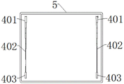
fig. 3 is a schematic top view of the drawing board of the present invention;
fig. 4 is a schematic structural diagram of the adjusting bracket of the present invention.
The reference numerals are explained below:
1. supporting the box body; 2. a support; 3. a rotating frame; 4. a paper pressing rod; 401. rotating the pressing block; 402. a telescopic rod; 403. a movable pressing block; 5. drawing boards; 6. an adjusting bracket; 601. a telescopic support rod; 602. a top rotating base; 603. positioning a knob; 604. the base is rotated at the bottom.
Detailed Description
In order to make the objects, technical solutions and advantages of the present invention clearer, the technical solutions of the present invention will be described in detail below. It is to be understood that the embodiments described are only some embodiments of the invention, and not all embodiments. Based on the embodiments of the present invention, all other embodiments obtained by a person skilled in the art without creative efforts belong to the protection scope of the present invention.
Referring to fig. 1-4, the utility model provides a drawing desk for mechanical design, including supporting box 1, support 2, manually adjust and lockable alignment jig 6 and drawing board 5, support 2 is fixed to one side of supporting box 1 top, alignment jig 6 is located the other side of supporting box 1 top, and the top of alignment jig 6 and the bottom of drawing board 5 are normal running fit, the bottom and the bottom of supporting box 1 are normal running fit, the bottom of drawing board 5 is installed with rotating turret 3, rotating turret 3 and support 2 are normal running fit through the round pin axle, after operating alignment jig 6 to make it retract and then fix, can adjust the contained angle between drawing board 5 and the horizontal plane, facilitate drawing and drawing looking over the operation;
a fly 4 is installed respectively to the symmetry both sides at 5 tops of drawing board, this fly 4 is by rotating briquetting 401, activity briquetting 403 and telescopic link 402 are constituteed, 5 tops of drawing board are provided with and rotate briquetting 401 normal running fit's rotation seat, telescopic link 402 one end is fixed at rotation briquetting 401 tip, the other end is fixed at activity briquetting 403 tip, during the drawing, tensile activity briquetting 403, take telescopic link 402 out, press the last border of drawing paper in rotation briquetting 401 below, and draw activity briquetting 403 to the lower border pressfitting of drawing paper, can fix the drawing paper.
As an optional implementation mode, a double-door-opening type box door structure is arranged on one side of the supporting box body 1, and drawing tools and drawings can be placed in the supporting box body 1 through the openable hollow supporting box body 1;
four corners of the bottom of the supporting box body 1 are provided with four lockable universal wheels, and equipment can be conveniently moved through universal joint;
the adjusting frame 6 comprises a telescopic supporting rod 601, a top rotating seat 602 and a bottom rotating seat 604, the top rotating seat 602 is fixed at the top of the drawing board 5, the bottom rotating seat 604 is fixed at the top of the supporting box body 1, two ends of the telescopic supporting rod 601 are respectively in rotating fit with the top rotating seat 602 and the bottom rotating seat 604, a positioning knob 603 for telescopic positioning is arranged on the telescopic supporting rod 601, the positioning knob 603 comprises a fixed end and a body length, the fixed end is in rotating fit with the bottom rotating seat 604, the positioning knob 603 penetrates through the side wall of the fixed end of the telescopic supporting rod 601 and is in threaded fit with the side wall, and by adjusting the positions of all parts in the paper pressing rod 4, the drawing edge at the top of the drawing board 5 can be pressed, and the drawing;
the front surface of the drawing board 5 is provided with a ferromagnetic patch, the rotating pressing block 401 and the movable pressing block 403 are both magnets, and the rotating pressing block 401 and the movable pressing block 403 can be stably connected with the ferromagnetic patch through attraction of the ferromagnetic patch, so that the edges of the drawing can be conveniently pressed;
the rubber material sheaths are wrapped on the surfaces of the rotating pressing block 401 and the movable pressing block 403, so that the friction force between the rotating pressing block 401 and the movable pressing block 403 in contact with the drawing paper can be improved and the stability of drawing pressing is improved through the contact between the rubber material sheaths and the drawing paper;
The included angle between the drawing board 5 and the horizontal position can be adjusted through the matching of the adjusting frame 6 and the rotating frame 3, so that the drawing can be observed conveniently after drawing is finished;
in the drawing and observation process, the edges of the drawing are pressed and fixed through the telescopic paper pressing rod 4, so that the edges of the drawing can be prevented from being turned over, and the drawing is protected;
simple operation and convenient use.
The above description is only for the specific embodiments of the present invention, but the protection scope of the present invention is not limited thereto, and any person skilled in the art can easily think of the changes or substitutions within the technical scope of the present invention, and all should be covered within the protection scope of the present invention. Therefore, the protection scope of the present invention shall be subject to the protection scope of the claims.
Claims (7)
1. The drawing table for mechanical design is characterized by comprising a supporting box body (1), a support (2), a manually-adjusted and lockable adjusting frame (6) and a drawing board (5), wherein the support (2) is fixedly installed on one side of the top of the supporting box body (1), the adjusting frame (6) is located on the other side of the top of the supporting box body (1), the top end of the adjusting frame (6) is in rotating fit with the bottom of the drawing board (5), the bottom end of the adjusting frame (6) is in rotating fit with the bottom of the supporting box body (1), a rotating frame (3) is installed at the bottom of the drawing board (5), and the rotating frame (3) is in rotating fit with the support (2) through a pin shaft;
a fly ash (4) is installed respectively to the symmetry both sides at drawing board (5) top, and this fly ash (4) comprises rotation briquetting (401), activity briquetting (403) and telescopic link (402), drawing board (5) top be provided with rotate briquetting (401) normal running fit's rotation seat, telescopic link (402) one end is fixed rotate briquetting (401) tip, the other end is fixed activity briquetting (403) tip.
2. A drawing table for mechanical design according to claim 1, wherein: one side of the supporting box body (1) is provided with a double-door-opening type box door structure.
3. A drawing table for mechanical design according to claim 1, wherein: four lockable universal wheels are installed at four corners of the bottom of the supporting box body (1).
4. A drawing table for mechanical design according to claim 1, wherein: the adjustable shelf (6) rotates seat (602) and bottom including flexible bracing piece (601), top and rotates seat (604), the top rotates seat (602) to be fixed drawing board (5) top, the bottom rotates seat (604) to be fixed supporting box (1) top, the both ends of flexible bracing piece (601) respectively with the top rotate seat (602) with seat (604) normal running fit is rotated to the bottom, be provided with location knob (603) of flexible location on flexible bracing piece (601), location knob (603) run through the lateral wall of the stiff end of flexible bracing piece (601) and pass through screw-thread fit with this lateral wall.
5. A drawing table for mechanical design according to claim 1, wherein: the front surface of the drawing board (5) is provided with a ferromagnetic paster, and the rotary pressing block (401) and the movable pressing block (403) are both magnets.
6. A drawing table for mechanical design according to claim 1, wherein: the surfaces of the rotary pressing block (401) and the movable pressing block (403) are wrapped with rubber material sheaths.
7. A drawing table for mechanical design according to claim 1, wherein: the periphery of the drawing board (5) is provided with arc-shaped rubber welts.
Priority Applications (1)
| Application Number | Priority Date | Filing Date | Title |
|---|---|---|---|
| CN201822127153.9U CN209883399U (en) | 2018-12-18 | 2018-12-18 | Drawing desk for mechanical design |
Applications Claiming Priority (1)
| Application Number | Priority Date | Filing Date | Title |
|---|---|---|---|
| CN201822127153.9U CN209883399U (en) | 2018-12-18 | 2018-12-18 | Drawing desk for mechanical design |
Publications (1)
| Publication Number | Publication Date |
|---|---|
| CN209883399U true CN209883399U (en) | 2020-01-03 |
Family
ID=69015499
Family Applications (1)
| Application Number | Title | Priority Date | Filing Date |
|---|---|---|---|
| CN201822127153.9U Expired - Fee Related CN209883399U (en) | 2018-12-18 | 2018-12-18 | Drawing desk for mechanical design |
Country Status (1)
| Country | Link |
|---|---|
| CN (1) | CN209883399U (en) |
Cited By (3)
| Publication number | Priority date | Publication date | Assignee | Title |
|---|---|---|---|---|
| CN111186247A (en) * | 2020-01-16 | 2020-05-22 | 南昌理工学院 | A device for carrying out sketching tools for art students |
| CN112293983A (en) * | 2020-10-20 | 2021-02-02 | 周蓓蓓 | Drawing frame for research and development design of individual weapon |
| CN114831421A (en) * | 2022-06-06 | 2022-08-02 | 浙江育英职业技术学院 | Efficiency-improved plane advertisement drawing design platform |
-
2018
- 2018-12-18 CN CN201822127153.9U patent/CN209883399U/en not_active Expired - Fee Related
Cited By (4)
| Publication number | Priority date | Publication date | Assignee | Title |
|---|---|---|---|---|
| CN111186247A (en) * | 2020-01-16 | 2020-05-22 | 南昌理工学院 | A device for carrying out sketching tools for art students |
| CN112293983A (en) * | 2020-10-20 | 2021-02-02 | 周蓓蓓 | Drawing frame for research and development design of individual weapon |
| CN114831421A (en) * | 2022-06-06 | 2022-08-02 | 浙江育英职业技术学院 | Efficiency-improved plane advertisement drawing design platform |
| CN114831421B (en) * | 2022-06-06 | 2023-09-05 | 浙江育英职业技术学院 | Planar advertisement drawing design platform capable of improving efficiency |
Similar Documents
| Publication | Publication Date | Title |
|---|---|---|
| CN210113618U (en) | Visual transmission design show stand for teaching | |
| CN208160407U (en) | The dedicated drawing workbench of indoor design Freehandhand-drawing | |
| CN206182666U (en) | Drawing device for art design of convenient contrast mapping | |
| CN109106072A (en) | A kind of clothes processing design table | |
| CN207710742U (en) | A kind of dress designing operation console of angle adjustable | |
| CN214355315U (en) | Multi-functional fine arts drawing board for drawing | |
| CN210743471U (en) | Intelligent advertisement design platform | |
| CN209931876U (en) | Foldable fine arts drawing table | |
| CN210139745U (en) | High-efficiency drawing board for students | |
| CN215244112U (en) | Drawing board for art design | |
| CN210657601U (en) | Flanging machine is used in carpet production | |
| CN220423424U (en) | Industrial design drawing device | |
| CN209883401U (en) | Indoor decoration is with supplementary drawing device | |
| CN211323570U (en) | Easel for industrial art convenient to fold and carry | |
| CN222003359U (en) | A foldable hardware tool table | |
| CN215382120U (en) | Rotary office table for office work | |
| CN209688415U (en) | High Strength Printer Accessories | |
| CN206757477U (en) | A kind of computer lift rack | |
| CN211176098U (en) | Combined type movable support | |
| CN212025715U (en) | Clothes ironing platform | |
| CN220076029U (en) | Height-adjustable's student drawing board | |
| CN214928640U (en) | A copy device for animation design hand-painting that is convenient for drawing paper to be fixed | |
| CN212945750U (en) | Fixing device for cutting aluminum alloy plates | |
| CN221284979U (en) | Drawing device for process design | |
| CN214803192U (en) | A study aid bracket for business English |
Legal Events
| Date | Code | Title | Description |
|---|---|---|---|
| GR01 | Patent grant | ||
| GR01 | Patent grant | ||
| CF01 | Termination of patent right due to non-payment of annual fee |
Granted publication date: 20200103 Termination date: 20201218 |
|
| CF01 | Termination of patent right due to non-payment of annual fee |