CN203678558U - Whirl-type cavitating spray head - Google Patents
Whirl-type cavitating spray head Download PDFInfo
- Publication number
- CN203678558U CN203678558U CN201320823914.9U CN201320823914U CN203678558U CN 203678558 U CN203678558 U CN 203678558U CN 201320823914 U CN201320823914 U CN 201320823914U CN 203678558 U CN203678558 U CN 203678558U
- Authority
- CN
- China
- Prior art keywords
- pressure water
- whirl
- spray head
- water pipe
- shell body
- Prior art date
- Legal status (The legal status is an assumption and is not a legal conclusion. Google has not performed a legal analysis and makes no representation as to the accuracy of the status listed.)
- Expired - Fee Related
Links
Images
Abstract
The utility model discloses a whirl-type cavitating spray head. The whirl-type cavitating spray head comprises an outer shell, wherein the front end of the outer shell is a thin pipe section; an outer nozzle is mounted at the outer end of the thin pipe section; a high-pressure water pipe is arranged inside the outer shell; a high-pressure water inlet is formed in one end of the high-pressure water pipe; a conic cylindrical inner nozzle is formed in the other end of the high-pressure water pipe; a low-pressure water cavity is formed between the inner wall of the outer shell and the outer wall of the high-pressure water pipe; rightwards spirally-arranged inner flow deflectors are arranged on the inner wall of the inner nozzle; a conic cylindrical transitional section is arranged between the outer shell and the thin pipe section; rightwards spirally-arranged outer flow deflectors are arranged on the inner wall of the transitional section. The whirl-type cavitating spray head is ingenious in structure; through the spirally-arranged flow deflectors, pressure water is formed into a whirl, so that the mixing effect is improved; the whirl-type cavitating spray head is provided with a mixing cavity for mixing high-pressure water flow and low-pressure water flow and adopts a backflow-preventing structure, so that the whirl-type cavitating spray head can improve the water flow spraying effect; the whirl-type cavitating spray head is convenient to mount.
Description
technical field:
The utility model relates to shower nozzle, is mainly spiral-flow type cavitation shower nozzle.
background technology:
Cavitation jet is that solid jet is modulated into a kind of novel jet flow with strong pressure oscillation and high cavitation threshold energy power, be mainly used on the cleaning technique of hull or pipeline, thereby coordinate cavitation jet need to have special cavitation shower nozzle, in order to improve jeting effect.
utility model content:
Technical problem to be solved in the utility model is to provide spiral-flow type cavitation shower nozzle, and its structure is ingenious, is provided with the hybrid chamber of High-Pressure Water and low pressure water flow, has backflow preventing structure simultaneously, improves water flow jet effect, easy for installation.
For solving the problems of the technologies described above, the technical solution adopted in the utility model is:
Spiral-flow type cavitation shower nozzle, comprises shell body, and shell body front end is tubule section, and tubule section is provided with outer nozzle on outer end, in described shell body, is provided with high-pressure water pipe, and high-pressure water pipe one end is high pressure intake, and the other end is the inner nozzle of cone tubular; Between shell body inwall and high-pressure water pipe outer wall, it is low pressure water cavity, described inner nozzle inwall is provided with the interior flow deflector that right-hand screw shape is arranged, the changeover portion that has cone tubular between described shell body and tubule section, changeover portion inwall is provided with the outer flow deflector that right-hand screw shape is arranged.
Its structure of the utility model is ingenious, and press water is formed eddy flow by the flow deflector of arranging by helical form, thereby improves mixed effect, is provided with the hybrid chamber of High-Pressure Water and low pressure water flow, has backflow preventing structure simultaneously, improves water flow jet effect, easy for installation.
The utility model has the advantages that:
Its structure of the utility model is ingenious, is provided with the hybrid chamber of High-Pressure Water and low pressure water flow, has backflow preventing structure simultaneously, improves water flow jet effect, easy for installation.
brief description of the drawings:
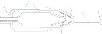
Fig. 1 is structural representation of the present utility model.
detailed description of the invention:
Referring to Fig. 1, spiral-flow type cavitation shower nozzle, comprises shell body 1, and shell body 1 front end is tubule section 2, and tubule section is provided with outer nozzle 3 on 2 outer ends, is provided with high-pressure water pipe 4 in shell body 1, and high-pressure water pipe 4 one end are high pressure intake, and the other end is the inner nozzle 5 of cone tubular; Between shell body inwall and high-pressure water pipe outer wall, it is low pressure water cavity 6, described inner nozzle 5 inwalls are provided with the interior flow deflector 7 that right-hand screw shape is arranged, the changeover portion that has cone tubular between described shell body and tubule section, changeover portion inwall is provided with the outer flow deflector 8 that right-hand screw shape is arranged.
Claims (1)
1. spiral-flow type cavitation shower nozzle, comprises shell body, and shell body front end is tubule section, tubule section is provided with outer nozzle on outer end, it is characterized in that: in described shell body, be provided with high-pressure water pipe, high-pressure water pipe one end is high pressure intake, the other end is the inner nozzle of cone tubular; Between shell body inwall and high-pressure water pipe outer wall, it is low pressure water cavity, described inner nozzle inwall is provided with the interior flow deflector that right-hand screw shape is arranged, the changeover portion that has cone tubular between described shell body and tubule section, changeover portion inwall is provided with the outer flow deflector that right-hand screw shape is arranged.
Priority Applications (1)
| Application Number | Priority Date | Filing Date | Title |
|---|---|---|---|
| CN201320823914.9U CN203678558U (en) | 2013-12-12 | 2013-12-12 | Whirl-type cavitating spray head |
Applications Claiming Priority (1)
| Application Number | Priority Date | Filing Date | Title |
|---|---|---|---|
| CN201320823914.9U CN203678558U (en) | 2013-12-12 | 2013-12-12 | Whirl-type cavitating spray head |
Publications (1)
| Publication Number | Publication Date |
|---|---|
| CN203678558U true CN203678558U (en) | 2014-07-02 |
Family
ID=51000520
Family Applications (1)
| Application Number | Title | Priority Date | Filing Date |
|---|---|---|---|
| CN201320823914.9U Expired - Fee Related CN203678558U (en) | 2013-12-12 | 2013-12-12 | Whirl-type cavitating spray head |
Country Status (1)
| Country | Link |
|---|---|
| CN (1) | CN203678558U (en) |
Cited By (8)
| Publication number | Priority date | Publication date | Assignee | Title |
|---|---|---|---|---|
| CN105481054A (en) * | 2015-12-30 | 2016-04-13 | 陕西师范大学 | Jet loop reactor with guiding body component |
| CN105540737A (en) * | 2015-12-30 | 2016-05-04 | 陕西师范大学 | Hydraulic acoustic cavitation circulation flow reactor |
| CN105621529A (en) * | 2015-12-30 | 2016-06-01 | 陕西师范大学 | Impinging stream strengthened hydraulic acoustic generator |
| CN106076921A (en) * | 2016-06-15 | 2016-11-09 | 湖州南浔展辉分子筛厂 | A kind of cleaning device of carbon molecular sieve |
| CN108970825A (en) * | 2018-08-09 | 2018-12-11 | 江苏大学镇江流体工程装备技术研究院 | A kind of gas-liquid mixed jet spray device |
| CN111515041A (en) * | 2020-03-20 | 2020-08-11 | 北京国利衡清洁能源科技(集团)有限公司 | Gasifying agent and water mixed atomizing nozzle and atomizing method thereof |
| CN111826513A (en) * | 2019-04-22 | 2020-10-27 | 中国科学院沈阳自动化研究所 | Impact strengthening device based on cavitation impact effect |
| CN116589028A (en) * | 2023-06-09 | 2023-08-15 | 浙江路弘科技有限公司 | Hydrodynamic cavitation generator and cavitation method |
-
2013
- 2013-12-12 CN CN201320823914.9U patent/CN203678558U/en not_active Expired - Fee Related
Cited By (12)
| Publication number | Priority date | Publication date | Assignee | Title |
|---|---|---|---|---|
| CN105481054A (en) * | 2015-12-30 | 2016-04-13 | 陕西师范大学 | Jet loop reactor with guiding body component |
| CN105540737A (en) * | 2015-12-30 | 2016-05-04 | 陕西师范大学 | Hydraulic acoustic cavitation circulation flow reactor |
| CN105621529A (en) * | 2015-12-30 | 2016-06-01 | 陕西师范大学 | Impinging stream strengthened hydraulic acoustic generator |
| CN105481054B (en) * | 2015-12-30 | 2018-01-12 | 陕西师范大学 | A kind of injection circulation reactor with guide way component |
| CN105540737B (en) * | 2015-12-30 | 2018-05-08 | 陕西师范大学 | A kind of waterpower acoustic cavitation circulation flow reactor |
| CN106076921A (en) * | 2016-06-15 | 2016-11-09 | 湖州南浔展辉分子筛厂 | A kind of cleaning device of carbon molecular sieve |
| CN108970825A (en) * | 2018-08-09 | 2018-12-11 | 江苏大学镇江流体工程装备技术研究院 | A kind of gas-liquid mixed jet spray device |
| CN108970825B (en) * | 2018-08-09 | 2023-07-04 | 江苏大学镇江流体工程装备技术研究院 | Gas-liquid mixed jet injection device |
| CN111826513A (en) * | 2019-04-22 | 2020-10-27 | 中国科学院沈阳自动化研究所 | Impact strengthening device based on cavitation impact effect |
| CN111515041A (en) * | 2020-03-20 | 2020-08-11 | 北京国利衡清洁能源科技(集团)有限公司 | Gasifying agent and water mixed atomizing nozzle and atomizing method thereof |
| CN116589028A (en) * | 2023-06-09 | 2023-08-15 | 浙江路弘科技有限公司 | Hydrodynamic cavitation generator and cavitation method |
| CN116589028B (en) * | 2023-06-09 | 2024-02-20 | 浙江路弘科技有限公司 | Hydrodynamic cavitation generator and cavitation method |
Similar Documents
| Publication | Publication Date | Title |
|---|---|---|
| CN203678558U (en) | Whirl-type cavitating spray head | |
| CN203030426U (en) | Three-way joint ejector | |
| CN102941172B (en) | Mixed liquid foaming device | |
| CN203531058U (en) | One-hole or multi-hole air injection water-saving and pressurizing faucet water outlet nozzle | |
| CN201848334U (en) | Inspiration type water saving shower head | |
| CN201744417U (en) | Novel hydraulic spray nozzle for carrying out high-pressure hydraulic deep penetration horizontal drilling | |
| CN202951591U (en) | Mixed liquid foaming device | |
| CN203061321U (en) | Electric spray gun with telescopic rod | |
| CN202725380U (en) | Spray nozzle | |
| CN105251629A (en) | Water rotating gas direct spraying type pole plate spraying washing device | |
| CN203725288U (en) | Backflow-prevention type cavitation spray nozzle | |
| CN207591643U (en) | A kind of cavitation bubble generator | |
| CN203448003U (en) | Venturi spraying pipe of spraying mixer | |
| CN203586864U (en) | Integrated high-pressure fluid heat exchanger | |
| CN207839207U (en) | A kind of cavitation chamber has the high pressure cavitation jet combination nozzle of roughness | |
| CN207839210U (en) | A kind of high pressure cavitation jet combination nozzle with conic nozzle entrance | |
| CN207839209U (en) | A kind of high pressure cavitation jet combination nozzle with tapered larynx section cavity | |
| CN105345675B (en) | Cyclone water direct injection band sand flusher | |
| CN205904010U (en) | Coal slurry boiler thick liquid rifle washing unit | |
| CN204532995U (en) | A kind of jetting stream vacuum pump structure | |
| CN203578055U (en) | Water-saving air-injection pressurizing sprinkler | |
| CN204544526U (en) | A kind of foam maker for jetting machine | |
| CN203044204U (en) | Throttling buffer nozzle | |
| CN202479062U (en) | Novel water-adding nozzle | |
| CN202993702U (en) | Noise reduction structure of liquid storage device of evaporator |
Legal Events
| Date | Code | Title | Description |
|---|---|---|---|
| C14 | Grant of patent or utility model | ||
| GR01 | Patent grant | ||
| CF01 | Termination of patent right due to non-payment of annual fee |
Granted publication date: 20140702 Termination date: 20141212 |
|
| EXPY | Termination of patent right or utility model |