CN203662258U - Theory and practice integration desk - Google Patents
Theory and practice integration desk Download PDFInfo
- Publication number
- CN203662258U CN203662258U CN201420039491.6U CN201420039491U CN203662258U CN 203662258 U CN203662258 U CN 203662258U CN 201420039491 U CN201420039491 U CN 201420039491U CN 203662258 U CN203662258 U CN 203662258U
- Authority
- CN
- China
- Prior art keywords
- desk
- guide rail
- tool box
- flip piece
- draughting board
- Prior art date
- Legal status (The legal status is an assumption and is not a legal conclusion. Google has not performed a legal analysis and makes no representation as to the accuracy of the status listed.)
- Expired - Fee Related
Links
Images


Abstract
The utility model discloses a theory and practice integration desk. The theory and practice integration desk comprises desk legs which are in vertical shapes, bottom frames which are arranged at lower ends of the desk legs, extensible type rolling mechanisms which are arranged at four corners of the bottom frames, a tool box which is arranged at upper ends of the table legs, a guide rail mechanism which is installed on the tool box, a desk top which is fixed on an upper surface of the tool box and a drawing board; the bottom frames are in I shapes; the desk top and the guide rail mechanism are in the same plane; the drawing board which is arranged on the desk top is connected with the guide rail mechanism through a turnover part and a limit part. According to the theory and practice integration desk, a structure which is skillfully designed according to different using conditions of the desk and aiming at numerous inconveniences in actual teaching confirms to different using requirements due to flexible adjustment of the desk using states according to a turnover and combined type principle, so that space resources are fully saved, teaching resource modules are integrated, and teaching is simplified and convenient.
Description
Technical field
The utility model relates to a kind of teaching aid, and specifically, what relate to is the real integrated desk of a kind of reason.
Background technology
Present desk generally only have a function or purposes comparatively single; popularizing due to modes such as multimedia teaching, audio-visual education programme, net religions in daily teaching; student usually there will be often conversion between real training building, audio-visual education room, computer classroom and teaching building; this reduces learning efficiency; and instructional space utilization rate is low, special classroom must be prepared by school just can carry out the corresponding content of courses.Especially when laboratory, also often need movable desk, adjust desk in actual use, existing desk moves also comparatively inconvenience, and the mode of student's movable desk drags often, and this has larger damage to desk, affects its service life.
Therefore, designing a kind of abundant contact modern teaching demand, meeting theory is that numerous teachers and students are required in conjunction with the teaching purpose of practical operation and the teaching platform of feature richness.
Utility model content
For problems of the prior art, the utility model provides a kind of abundant contact modern teaching demand, meets theory in conjunction with the teaching purpose of practical operation and the real integrated desk of the reason of feature richness.
To achieve these goals, the technical solution adopted in the utility model is as follows:
The real integrated desk of reason, comprise the table leg that is vertical shape, be arranged at the underframe that is I shape of table leg lower end, be arranged on the Telescopic rolling mechanism of four jiaos, underframe, be arranged at the tool box of table leg upper end, be arranged on the guide rail mechanism on tool box, be fixed on tool box upper surface and with guide rail mechanism the desk top in same plane, and be positioned at the draughting board being connected with guide rail mechanism with locating part on desk top and by flip piece.
Further, described guide rail mechanism comprises two detachable guide rail body that are installed on desk top both sides on tool box and are parallel arrangement, be arranged in guide rail body for connecting the gathering sill of flip piece, in guide rail body, be made as fillet near one end of flip piece, and in the gathering sill of this end, be provided with after being convenient to be connected with flip piece and overturn and limit the pin that flip piece laterally shifts out.
Further, described flip piece comprises the contiguous block being fixedly connected with draughting board, and be with this contiguous block the dumbbell connecting rod that turning form is flexibly connected, wherein, on contiguous block, offer and the first mounting groove of dumbbell connecting rod one end coupling and the second mounting groove that is communicated with the first mounting groove and mates with dumbbell connecting rod middle part, and the cross sectional shape of gathering sill and dumbbell connecting rod other end form fit, be the little shape of Di great Ding.
Further, locating part has two kinds of set-up modes, a kind of for described locating part comprises and is arranged on the limited block away from flip piece one end in guide rail body, and the stopper slot that is opened in the draughting board back side and mates with limited block.
Another kind of for described locating part comprises the hinged support bar in one end and the draughting board back side, and be arranged at the stopper slot mating in guide rail body and with the support bar other end.
Further, described draughting board is provided with projection away from one end of flip piece, this respective end in guide rail body or desk top or tool box be provided with mate with this projection on draughting board, turn over mobile fastener for preventing;
Or draughting board is provided with fastener away from one end of flip piece, this respective end in guide rail body or desk top or tool box be provided with mate with this fastener on draughting board, turn over mobile projection for preventing.
Further, described Telescopic rolling mechanism comprises and is arranged on underframe and is with female installation cavity, be placed in installation cavity with it form fit and with the externally threaded ball jacket mating with internal thread, be placed in ball jacket bottom and be limited to ball jacket rotatable mobile ball, and be arranged on the telescopic adjustment part on underframe with the helical structure mating with the external screw thread of ball jacket.
For the convenient large part objects such as books of placing, between described table leg, be provided with the rack of liftable adjusting position.
For improving degree easy to use, described tool box is drawer-type structure.
In order to realize better the utility model, the side of described table leg is provided with the Storing case for placing machine element.
Compared with prior art, the utlity model has following beneficial effect:
(1) the utility model is for the inconvenience situation of field research work, the behaviour in service different according to desk, designing dexterously this utilization upset combined type principle can use state to meet the structure of its different user demands by accommodation desk, save fully space resources, integrated instruction resource module, more make teaching become simplicity, more convenient, there is substantive distinguishing features and progress, and it is simple that the utility model structure still keeps, with low cost, easy to use, there is market application foreground widely, be applicable to applying.
(2) the utility model utilizes the cooperation of guide rail mechanism and flip piece, locating part to realize draughting board face fixing, upset, angular adjustment, position are moved and are dismantled, easy to use, rational in infrastructure, complete realistic user demand, has embodied abundant functionalization and hommization.
(3) the utility model arranges the rolling mechanism of scalable adjusting on underframe, regulate in use to shrink and fully guaranteed the stability using, in the time that needs move, easily adjust regulating part and make that roller is outstanding can be moved flexibly easily, be extremely convenient to seminar group and carry out independent assortment discussion or experiment.
(4) the utility model not only arranges the tool box of zero widgets such as place tool, and the rack of being convenient to place large part object is also set, and can facilitate student to place the article such as books, and its height is adjustable on table leg, its use of being more convenient for.
(5) the utility model also arranges the Storing case of corresponding placement computer fittings in conjunction with Modern Information based teaching method, arrange in pairs or groups with desk, audio-visual education programme, net religion are organically combined with conventional teaching, and make student's easy and convenient ground of energy operating routine computer graphics software on classroom as CAD, UG, PS etc., further embody fully the modern education mode of theory and practice combination.
Accompanying drawing explanation
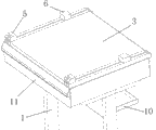
Fig. 1 is overall structure schematic diagram of the present utility model.
Fig. 2 is the structural representation of the utility model dismounting draughting board upper back.
Fig. 3 is the structural representation of guide rail mechanism of the present utility model.
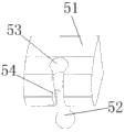
Fig. 4 is the structural representation of flip piece of the present utility model.
Fig. 5 is the partial structurtes schematic diagram of underframe of the present utility model.
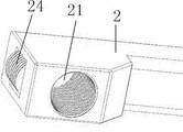
Fig. 6 is the structural representation of mobile ball part of the present utility model.
In above-mentioned accompanying drawing, the component names that Reference numeral is corresponding is as follows:
1-table leg, 2-underframe, 3-desk top, 4-draughting board, 5-flip piece, 6-locating part, 7-guide rail body, 8-gathering sill, 9-pin, 10-rack, 11-tool box; 21-installation cavity, 22-ball jacket, 23-moves ball, 24-telescopic adjustment part; 51-contiguous block, 52-dumbbell connecting rod, 53-the first mounting groove, 54-the second mounting groove.
The specific embodiment
Below in conjunction with drawings and Examples, the utility model is described in further detail, and embodiment of the present utility model includes but not limited to the following example.
Embodiment
As shown in Figures 1 to 6, the real integrated desk of this reason, comprise the table leg 1 that is vertical shape, be arranged at the underframe that is I shape 2 of table leg lower end, be arranged on the Telescopic rolling mechanism of four jiaos, underframe, be arranged at the tool box 11 of table leg upper end, be arranged on the guide rail mechanism on tool box, be fixed on tool box upper surface and with guide rail mechanism the desk top 3 in same plane, and the draughting board 4 that is positioned on desk top and is connected with guide rail mechanism with locating part 6 by flip piece 5.
Wherein, described guide rail mechanism comprises two detachable guide rail body 7 that are installed on desk top both sides on tool box and are parallel arrangement, be arranged in guide rail body for connecting the gathering sill 8 of flip piece, in guide rail body, be made as fillet near one end of flip piece, and in the gathering sill of this end, be provided with after being convenient to be connected with flip piece and overturn and limit the pin 9 that flip piece laterally shifts out.
Further, described flip piece comprises the contiguous block 51 being fixedly connected with draughting board, and be with this contiguous block the dumbbell connecting rod 52 that turning form is flexibly connected, wherein, on contiguous block, offer and the first mounting groove 53 of dumbbell connecting rod one end coupling and the second mounting groove 54 that is communicated with the first mounting groove and mates with dumbbell connecting rod middle part, and the cross sectional shape of gathering sill and dumbbell connecting rod other end form fit, be the little shape of Di great Ding.
And locating part has two kinds of set-up modes, the first is that described locating part comprises and is arranged on the limited block away from flip piece one end in guide rail body, and the stopper slot that is opened in the draughting board back side and mates with limited block.The second is that described locating part comprises the hinged support bar in one end and the draughting board back side, and is arranged at the stopper slot mating in guide rail body and with the support bar other end.And the first kind of way that the present embodiment is selected.
This structure that is used for fixing draughting board also can adopt two kinds of set-up modes, one is provided with projection for described draughting board away from one end of flip piece, this respective end in guide rail body or desk top or tool box be provided with mate with this projection on draughting board, turn over mobile fastener for preventing; Two are provided with fastener for draughting board away from one end of flip piece, this respective end in guide rail body or desk top or tool box be provided with mate with this fastener on draughting board, turn over mobile projection for preventing.
Further, described Telescopic rolling mechanism comprises and is arranged on underframe and is with female installation cavity 21, be placed in installation cavity with it form fit and with the externally threaded ball jacket 22 mating with internal thread, be placed in ball jacket bottom and be limited to ball jacket rotatable mobile ball 23, and be arranged on the telescopic adjustment part 24 on underframe with the helical structure mating with the external screw thread of ball jacket.For more convenient adjusting, in the installation cavity of ball jacket upper end, be also provided with Compress Spring.
For the convenient large part objects such as books of placing, between described table leg, be provided with the rack 10 of liftable adjusting position.For improving degree easy to use, described tool box is drawer-type structure.In order to realize better the utility model, the side of described table leg is provided with the Storing case for placing machine element.
The foregoing is only preferred embodiment of the present utility model; not in order to limit the utility model; all any modifications of doing within spirit of the present utility model and principle, be equal to and replace and improvement etc., within all should being included in protection domain of the present utility model.
According to above-described embodiment, just can realize well the utility model.What deserves to be explained is; under prerequisite based on said structure design; for solving same technical problem; even if some that make on the utility model are without substantial change or polishing; the essence of the technical scheme adopting is still consistent with the utility model, also should be in protection domain of the present utility model.
Claims (10)
1. the real integrated desk of reason, it is characterized in that, comprise the table leg (1) that is vertical shape, be arranged at the underframe that is I shape (2) of table leg lower end, be arranged on the Telescopic rolling mechanism of four jiaos, underframe, be arranged at the tool box (11) of table leg upper end, be arranged on the guide rail mechanism on tool box, be fixed on tool box upper surface and with guide rail mechanism the desk top in same plane (3), and the draughting board (4) that is positioned on desk top and is connected with guide rail mechanism with locating part (6) by flip piece (5).
2. the real integrated desk of reason according to claim 1, it is characterized in that, described guide rail mechanism comprises two detachable guide rail body (7) that are installed on desk top both sides on tool box and are parallel arrangement, be arranged in guide rail body for connecting the gathering sill (8) of flip piece, in guide rail body, be made as fillet near one end of flip piece, and in the gathering sill of this end, be provided with after being convenient to be connected with flip piece and overturn and limit the pin (9) that flip piece laterally shifts out.
3. the real integrated desk of reason according to claim 2, it is characterized in that, described flip piece comprises the contiguous block (51) being fixedly connected with draughting board, and be with this contiguous block the dumbbell connecting rod (52) that turning form is flexibly connected, wherein, on contiguous block, offer and first mounting groove (53) of dumbbell connecting rod one end coupling and the second mounting groove (54) that is communicated with the first mounting groove and mates with dumbbell connecting rod middle part, and the cross sectional shape of gathering sill and dumbbell connecting rod other end form fit, be the little shape of Di great Ding.
4. the real integrated desk of reason according to claim 2, is characterized in that, described locating part comprises and is arranged on the limited block away from flip piece one end in guide rail body, and the stopper slot that is opened in the draughting board back side and mates with limited block.
5. the real integrated desk of reason according to claim 2, is characterized in that, described locating part comprises the hinged support bar in one end and the draughting board back side, and is arranged at the stopper slot mating in guide rail body and with the support bar other end.
6. according to the real integrated desk of the reason described in claim 2~5 any one, it is characterized in that, described draughting board is provided with projection away from one end of flip piece, this respective end in guide rail body or desk top or tool box be provided with mate with this projection on draughting board, turn over mobile fastener for preventing;
Or draughting board is provided with fastener away from one end of flip piece, this respective end in guide rail body or desk top or tool box be provided with mate with this fastener on draughting board, turn over mobile projection for preventing.
7. according to the real integrated desk of the reason described in claim 1~5 any one, it is characterized in that, described Telescopic rolling mechanism comprises and is arranged on underframe and is with female installation cavity (21), be placed in installation cavity with it form fit and with the externally threaded ball jacket (22) mating with internal thread, be placed in ball jacket bottom and be limited to ball jacket rotatable mobile ball (23), and be arranged on the telescopic adjustment part (24) on underframe with the helical structure mating with the external screw thread of ball jacket.
8. the real integrated desk of reason according to claim 7, is characterized in that, is provided with the rack (10) of liftable adjusting position between described table leg.
9. the real integrated desk of reason according to claim 7, is characterized in that, described tool box is drawer-type structure.
10. the real integrated desk of reason according to claim 8 or claim 9, is characterized in that, the side of described table leg is provided with the Storing case for placing machine element.
Priority Applications (1)
| Application Number | Priority Date | Filing Date | Title |
|---|---|---|---|
| CN201420039491.6U CN203662258U (en) | 2014-01-22 | 2014-01-22 | Theory and practice integration desk |
Applications Claiming Priority (1)
| Application Number | Priority Date | Filing Date | Title |
|---|---|---|---|
| CN201420039491.6U CN203662258U (en) | 2014-01-22 | 2014-01-22 | Theory and practice integration desk |
Publications (1)
| Publication Number | Publication Date |
|---|---|
| CN203662258U true CN203662258U (en) | 2014-06-25 |
Family
ID=50958612
Family Applications (1)
| Application Number | Title | Priority Date | Filing Date |
|---|---|---|---|
| CN201420039491.6U Expired - Fee Related CN203662258U (en) | 2014-01-22 | 2014-01-22 | Theory and practice integration desk |
Country Status (1)
| Country | Link |
|---|---|
| CN (1) | CN203662258U (en) |
Cited By (3)
| Publication number | Priority date | Publication date | Assignee | Title |
|---|---|---|---|---|
| CN106308090A (en) * | 2016-11-14 | 2017-01-11 | 钦州学院 | Movable teaching desk |
| CN106798404A (en) * | 2017-03-15 | 2017-06-06 | 重庆工业职业技术学院 | The file that a kind of convenience file lines up to put lines up frame and its application method |
| CN110367695A (en) * | 2019-07-24 | 2019-10-25 | 河海大学常州校区 | Multifunctional desk and tables and chairs combination |
-
2014
- 2014-01-22 CN CN201420039491.6U patent/CN203662258U/en not_active Expired - Fee Related
Cited By (3)
| Publication number | Priority date | Publication date | Assignee | Title |
|---|---|---|---|---|
| CN106308090A (en) * | 2016-11-14 | 2017-01-11 | 钦州学院 | Movable teaching desk |
| CN106798404A (en) * | 2017-03-15 | 2017-06-06 | 重庆工业职业技术学院 | The file that a kind of convenience file lines up to put lines up frame and its application method |
| CN110367695A (en) * | 2019-07-24 | 2019-10-25 | 河海大学常州校区 | Multifunctional desk and tables and chairs combination |
Similar Documents
| Publication | Publication Date | Title |
|---|---|---|
| CN205197393U (en) | Business administration teaching assistance board of imparting knowledge to students | |
| CN206137522U (en) | Multimedia school teaching desk for ideological and political education | |
| CN203662258U (en) | Theory and practice integration desk | |
| CN202495167U (en) | Interactive multimedia teaching device | |
| CN202552851U (en) | Multifunctional desk | |
| CN203860707U (en) | Portable multifunctional drawing frame | |
| CN203314410U (en) | Teaching frame with adjustment function | |
| CN204861816U (en) | Multimedia teaching podium | |
| CN202514958U (en) | Learning table with movable blackboards | |
| CN211510962U (en) | Interactive installation that computer teaching was used | |
| CN203073585U (en) | Novel multimedia teaching platform | |
| CN209219468U (en) | A kind of new multistage desktop adjustable middle desk | |
| CN106263613A (en) | A kind of desk of drawer variable volume | |
| CN207754799U (en) | A kind of drawing multifunctional platform | |
| CN203931251U (en) | Civil law moot court | |
| CN202999901U (en) | Practical desk | |
| CN204516129U (en) | A kind of Political Teaching Graphic Panel | |
| CN201734154U (en) | Lifting type demonstration experiment table for classroom | |
| CN205281828U (en) | English language learning teaching platform | |
| CN209047554U (en) | A kind of Novel rostrum | |
| CN214483701U (en) | Multifunctional teaching desk for literal arts | |
| CN203041244U (en) | Split type desk | |
| CN203986818U (en) | A kind of novel desk | |
| CN202874414U (en) | Study table special for students | |
| CN209121748U (en) | A kind of student's Chinese language works display board |
Legal Events
| Date | Code | Title | Description |
|---|---|---|---|
| C14 | Grant of patent or utility model | ||
| GR01 | Patent grant | ||
| CF01 | Termination of patent right due to non-payment of annual fee |
Granted publication date: 20140625 Termination date: 20160122 |
|
| EXPY | Termination of patent right or utility model |