CN203658460U - Family environmentally-friendly electricity utilization indicating device - Google Patents
Family environmentally-friendly electricity utilization indicating device Download PDFInfo
- Publication number
- CN203658460U CN203658460U CN201320875653.5U CN201320875653U CN203658460U CN 203658460 U CN203658460 U CN 203658460U CN 201320875653 U CN201320875653 U CN 201320875653U CN 203658460 U CN203658460 U CN 203658460U
- Authority
- CN
- China
- Prior art keywords
- electricity consumption
- indicating device
- electricity utilization
- family
- real
- Prior art date
- Legal status (The legal status is an assumption and is not a legal conclusion. Google has not performed a legal analysis and makes no representation as to the accuracy of the status listed.)
- Expired - Fee Related
Links
- 230000005611 electricity Effects 0.000 title claims abstract description 67
- 239000003990 capacitor Substances 0.000 claims abstract description 16
- 230000001939 inductive effect Effects 0.000 claims description 12
- 230000000630 rising effect Effects 0.000 claims description 2
- 238000013459 approach Methods 0.000 abstract description 4
- 230000003993 interaction Effects 0.000 abstract description 3
- 238000012986 modification Methods 0.000 abstract description 2
- 230000004048 modification Effects 0.000 abstract description 2
- 230000006698 induction Effects 0.000 abstract 1
- 239000007789 gas Substances 0.000 description 6
- 238000004891 communication Methods 0.000 description 5
- 238000012544 monitoring process Methods 0.000 description 5
- 210000000080 chela (arthropods) Anatomy 0.000 description 3
- 238000011161 development Methods 0.000 description 3
- 230000018109 developmental process Effects 0.000 description 3
- 238000003860 storage Methods 0.000 description 3
- 230000005540 biological transmission Effects 0.000 description 2
- 230000009514 concussion Effects 0.000 description 2
- 238000010586 diagram Methods 0.000 description 2
- 230000000694 effects Effects 0.000 description 2
- 238000005516 engineering process Methods 0.000 description 2
- 230000007613 environmental effect Effects 0.000 description 2
- 230000002452 interceptive effect Effects 0.000 description 2
- 238000012806 monitoring device Methods 0.000 description 2
- 238000011160 research Methods 0.000 description 2
- 230000009466 transformation Effects 0.000 description 2
- UGFAIRIUMAVXCW-UHFFFAOYSA-N Carbon monoxide Chemical compound [O+]#[C-] UGFAIRIUMAVXCW-UHFFFAOYSA-N 0.000 description 1
- 238000004378 air conditioning Methods 0.000 description 1
- 230000009286 beneficial effect Effects 0.000 description 1
- 229910002091 carbon monoxide Inorganic materials 0.000 description 1
- 238000004134 energy conservation Methods 0.000 description 1
- JEIPFZHSYJVQDO-UHFFFAOYSA-N ferric oxide Chemical compound O=[Fe]O[Fe]=O JEIPFZHSYJVQDO-UHFFFAOYSA-N 0.000 description 1
- 239000004973 liquid crystal related substance Substances 0.000 description 1
- 230000000505 pernicious effect Effects 0.000 description 1
- 238000012545 processing Methods 0.000 description 1
- 238000005070 sampling Methods 0.000 description 1
- 230000011218 segmentation Effects 0.000 description 1
- 230000008054 signal transmission Effects 0.000 description 1
Images

Landscapes
- Remote Monitoring And Control Of Power-Distribution Networks (AREA)
Abstract
The utility model provides a family environmentally-friendly electricity utilization indicating device. The device consists of a real-time current pulse signal acquisition device and a real-time electricity utilization indicating device. A Split-core type current transformer in the real-time current pulse signal acquisition device is arranged at an existing home-entry wiring entering end in a clamped manner, and therefore, real-time electricity utilization indicating can be realized under the premise that no modification is made on an existing circuit; the real-time current pulse signal acquisition device comprises the Split-core type current transformer, a voltage-doubling rectifier, a super capacitor, a voltage comparator, an oscillator, a power amplifier and a radio pulse transmitter; the radio pulse transmitter can emit pulse strings of different frequencies; with the increase of the frequencies, an electricity utilization early-warning indicating lamp gradually becomes red from green, and therefore, a user can be prompted intuitively that current electricity utilization approaches a set threshold value. The family environmentally-friendly electricity utilization indicating device is of structural simplicity. According to the family environmentally-friendly electricity utilization indicating device, an infrared induction switch is adopted, the device only performs display when people look at the device, and therefore, electricity can be effectively saved. A DSP touch display screen recognizes the transmitting frequencies of the pulse strings in one minute and stores the transmitting frequencies, and computes current and electricity utilization data through specific formulas, and stores the current and the electricity utilization data. With the family environmentally-friendly electricity utilization indicating device adopted, human-computer interaction and data acquisition can be realized, and daily electricity utilization curves can be displayed in real time, and monthly electricity utilization curves, historical electricity utilization curves, current period electricity price and current electricity utilization suggestions can be inquired.
Description
Technical field
The utility model relates to the green electricity consumption indicating device of a kind of family, and particularly a kind of green electricity consumption indicating device of intelligent family that utilizes wireless pulses transmitter, belongs to the green electricity consumption indication of intelligent family field.
Background technology
Along with development and increasing industry experts and research institution the showing great attention to and high investment intelligent grid research of intelligent grid technology, build intelligent grid, strengthen the reliability of operation of power networks, oneself is brought or includes in into schedule development plan by numerous countries and regions to improve power supply quality.Therefore the household electricity control terminal of building a set of intelligence is the road of the certainty of intelligent grid development.Existing electricity consumption acquisition terminal possesses basic data sampling and processing, storage and control function, gather and store power information by smart jack, thereby the electric power application system on terminal and upper strata realizes the power consumption control to household alternately simultaneously, but mounting means complexity, need to transform existing circuit.
Patent: intelligent household electricity comprehensive monitoring system, application number 201220343563, a kind of intelligent household electricity comprehensive monitoring system is disclosed, comprise the controller that the multiple household electrical appliance to installing in monitored family are controlled respectively, the current Indoor Environmental Condition of monitored family is carried out to the Indoor Environmental Condition monitoring device of Real-Time Monitoring, the of that month power consumption of monitored family is carried out to the power consumption monitoring device of Real-Time Monitoring, approach when monitoring of that month power consumption the alarm unit that carries out automatic alarm prompting when the value of cutting off from is reported to the police in setting, according to parameter set unit that in step price, the corresponding power consumption of each ladder segmentation arranges warning value of cutting off from of alarm unit and the clock circuit and the wireless communication module that join with controller respectively, carry out two-way communication by wireless communication module and remote controllers.Patent: a kind of interactive intelligent electricity consumption service terminal arrangement flexibly, application number 201220222535.X, discloses a kind of flexible interactive intelligent electricity consumption service terminal arrangement, includes touch screen module, power information collecting unit, network service; Wherein power information collecting unit includes 485 communication a \ b mouth and power carrier communications; The network interface of network service is Ethernet interface; Power information collecting unit is connected with ammeter by 485 signal wires or line of electric force, and network service is connected with electric power application system by netting twine.Patent: a kind of household electricity, use gas energy-saving safe monitor terminal, application number 201210294264.3, disclose a kind of household electricity, used gas energy-saving safe monitor terminal, harmful gas in its liquefied gas sensor, carbon monoxide transducer sensing chamber, can automatically control vent fan work, to exhale pernicious gases, harmful gas after exhaust a period of time, still detected, will report to the police by sound, light, mobile phone short messages; Can be operatively connected to by keyboard input, infrared remote control or mobile phone short messages the work of the relay of air-conditioning and socket, control its power supply; By detecting gate, window magnetic switch, in the time that opening, door, window automatically close air conditioner power source, reach energy-conservation effect; The state of the each switch of LCD liquid crystal display, relay and sensor, is convenient to observe and operation; Can be long-range by the state of the each sensor of mobile phone short message enquiry, switch, relay, understand the situation in family, and the work of remote controlled relay.
Above patent is power consumption intelligent monitor system, but all how power consumption is not gathered and be described.
Patent: lighting power consumption gather and control device of wireless, application number 201210461957.7, disclose a kind of specific access way lighting power consumption harvester.
Utility model content
The utility model, for the existing problem of power consumption intelligent monitor system prior art, has proposed the green electricity consumption indicating device of a kind of family.Fundamental purpose utilizes electricity consumption of the present utility model to gather indicating device exactly, realizes real-time power consumption indication under the prerequisite of available circuit not being carried out any transformation.
The technical scheme that the utility model is taked is:
The utility model is made up of real-time current pulse signal acquisition device and real-time electricity consumption indicating device.
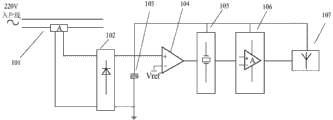
Described real-time current pulse signal acquisition device is made up of hook type current transformer, voltage-doubler rectifier, super capacitor, voltage comparator, oscillator, power amplifier, wireless pulse transmitter.Hook type current transformer pincers are placed on the existing end of incoming cables of registering one's residence, and are used for Real-time Collection current information.Voltage-doubler rectifier, super capacitor are voltage comparator, oscillator, power amplifier, the power supply of wireless pulse transmitter.Oscillator, power amplifier, wireless pulse transmitter are according to the umber of pulse of size of current transmitting different frequency.
Described real-time electricity consumption indicating device adopts greenery profile, is made up of inductive switch, electricity consumption early warning pilot lamp, DSP display device, radio signal indication and receiver, power supply.The indicating device that inductive switch is only shows when watching people, can effectively save power consumption.Electricity consumption early warning pilot lamp is used for showing in real time electricity consumption situation, and along with power consumption increases, pilot lamp moves towards red gradually by green, intuitively reminding user at that time power consumption approach the degree of setting threshold.DSP display device can be stored power consumption data and be realized man-machine interaction, and received current, voltage acquisition data carry out storing after logical operation, show when daily power consumption curve in real time, can inquire about this month power consumption curve, historical power consumption curve, this period electricity price, current power consumption suggestion.Radio signal indication and receiver are used for receiving wireless pulse and transmit, and to send to DSP display device, power unit be mobile battery and insert first two pattern.
The beneficial effects of the utility model are:
In the utility model, hook type current transformer pincers are placed on the existing end of incoming cables of registering one's residence, and can under the prerequisite of available circuit not being carried out any transformation, realize real-time electricity consumption indication.
An effect of the present invention is, in the present invention, size of current on service wire determines the charging rate of super capacitor, the charging rate of super capacitor determines the frequency of wireless pulse transmitter transmit burst: in the time that service wire hook type current transformer electric current is large, super capacitor charging rate is fast, and the frequency of wireless pulse transmitter transmit burst is just high; When service wire hook type current transformer electric current hour, when user power utilization amount is low, the frequency of wireless pulse transmitter transmit burst is just low.
In the utility model, indicate real-time electricity consumption situation by the train of impulses of wireless pulse transmitter transmitting different frequency, simple in structure.
In the utility model, electricity consumption indicating device adopt infrared sensing switch, device only people in watching show, can effectively save electric weight.
Accompanying drawing explanation
Fig. 1 is the real-time electricity consumption indicating device schematic diagram of the green electricity consumption indicating device of family in the utility model;
Fig. 2 is the real-time current pulse signal acquisition device schematic diagram of the green electricity consumption indicating device of family in the utility model;
Fig. 3 is the graph of relation of registering one's residence in the utility model between current i and wireless pulse transmission frequency f.
Embodiment
Embodiment:
The green electricity consumption indicating device of family, comprise: real-time current pulse signal acquisition device and in real time electricity consumption indicating device two parts, real-time current pulse signal acquisition device is made up of hook type current transformer 101, voltage-doubler rectifier 102, super capacitor 103, voltage comparator 104, oscillator 105, power amplifier 106, wireless pulse transmitter 107.Electricity consumption indicating device is made up of inductive switch 201, electricity consumption early warning pilot lamp 202, DSP display device 203, radio signal indication and receiver 204, power supply 205 in real time.
Current transformer (101), voltage-doubler rectifier (102), super capacitor (103), voltage comparator (104), oscillator (105), power amplifier (106), wireless pulse transmitter (107) are connected successively; Inductive switch (201), electricity consumption early warning pilot lamp (202), DSP display device (203), radio signal indication and receiver (204), power supply (205) are distributed on the panel of real-time electricity consumption indicating device, electrical connection mutually; Radio signal indication and receiver (204) are connected by radiowave with wireless pulse transmitter (107).
DSP display device (203) adopts DSP touch display screen, and inductive switch (201) adopts human body infrared inductive switch.
Hook type current transformer 101 pincers are placed on the existing end of incoming cables of registering one's residence, and are used for the Real-time Collection electric current of registering one's residence.Charge to super capacitor 103 by voltage-doubler rectifier 102, produce one group of concussion pulse signal through over-voltage comparator 104 oscillator 105 in the time that voltage reaches given voltage, and after power amplifier 106 amplifies, pass to wireless pulse transmitter 107 and be transmitted to radio signal indication and receiver 204.At this moment super capacitor 103 discharges, voltage is lower than voltage comparator 104 voltage setting values, continue to charge to super capacitor 103 by voltage-doubler rectifier 102, in the time that voltage reaches voltage comparator 104 voltage setting value, oscillator 105 continues to produce one group of concussion pulse signal, and after power amplifier 106 amplifies, passes to wireless pulse transmitter 107 and launch.Like this in the time that service wire hook type current transformer electric current is large, be that user power utilization amount is when high, super capacitor 103 charging rates are fast, the frequency of wireless pulse transmitter 107 transmit burst is just high, when service wire hook type current transformer electric current hour, be user power utilization amount when low, the frequency of wireless pulse transmitter 107 transmit burst is just low.
Whether radio signal indication and receiver 204 display radio signal transmissions are normal and receive train of impulses that wireless pulse transmitter 107 transmit burst send and be sent to DSP display device 203 and carry out computing and storage.The transmission frequency of DSP display device 203 identification pulse strings in 1 minute storage, then calculate and storaging current and power consumption data by specific publicity, thereby realize man-machine interaction, data acquisition, show when daily power consumption curve in real time, can inquire about this month power consumption curve, historical power consumption curve, this period electricity price, current power consumption suggestion.On electricity consumption early warning pilot lamp 202, along with the rising pilot lamp of frequency moves towards red gradually by green, reminding user electricity consumption at that time intuitively approaches the degree of setting threshold.
In electricity consumption indicating device, inductive switch 201 adopts human body infrared inductive switch, make device only people in watching show, can effectively save electric weight.Power supply 205 parts are mobile battery and insert first two pattern.
Above-described embodiment is preferred embodiments of the present utility model; but embodiment of the present utility model is not limited in this; other are any does not deviate from change, the modification done under Spirit Essence of the present utility model and principle, substitute, combination, simplify and the substitute mode of changing such as be, within being included in protection domain of the present utility model.
Claims (7)
1. the green electricity consumption indicating device of family, is characterized in that, formed by real-time current pulse signal acquisition device and real-time electricity consumption indicating device two parts, wherein,
Real-time current pulse signal acquisition device comprises hook type current transformer (101), voltage-doubler rectifier (102), super capacitor (103), voltage comparator (104), oscillator (105), power amplifier (106), wireless pulse transmitter (107);
Electricity consumption indicating device comprises inductive switch (201), electricity consumption early warning pilot lamp (202), DSP display device (203), radio signal indication and receiver (204), power supply (205) in real time;
Current transformer (101), voltage-doubler rectifier (102), super capacitor (103), voltage comparator (104), oscillator (105), power amplifier (106), wireless pulse transmitter (107) are connected successively;
Inductive switch (201), electricity consumption early warning pilot lamp (202), DSP display device (203), radio signal indication and receiver (204), power supply (205) are distributed on the panel of real-time electricity consumption indicating device, electrical connection mutually;
Radio signal indication and receiver (204) are connected by radiowave with wireless pulse transmitter (107).
2. the green electricity consumption indicating device of a kind of family as claimed in claim 1, is characterized in that, hook type current transformer (101) is by giving super capacitor (103) charging after voltage-doubler rectifier (102).
3. the green electricity consumption indicating device of a kind of family as claimed in claim 1, is characterized in that, super capacitor (103) is voltage comparator (104), oscillator (105), power amplifier (106), wireless pulse transmitter (107) power supply.
4. the green electricity consumption indicating device of a kind of family as claimed in claim 1, is characterized in that, DSP display device (203) adopts DSP touch display screen.
5. the green electricity consumption indicating device of a kind of family as claimed in claim 1, is characterized in that, inductive switch (201) adopts human body infrared inductive switch.
6. the green electricity consumption indicating device of a kind of family as claimed in claim 1, is characterized in that, electricity consumption early warning pilot lamp (202) is along with the rising of frequency moves towards red gradually by green.
7. the green electricity consumption indicating device of a kind of family as claimed in claim 1, is characterized in that, electricity consumption indicating device adopts Green leaf-shaped appearance design in real time.
Priority Applications (1)
| Application Number | Priority Date | Filing Date | Title |
|---|---|---|---|
| CN201320875653.5U CN203658460U (en) | 2013-12-26 | 2013-12-26 | Family environmentally-friendly electricity utilization indicating device |
Applications Claiming Priority (1)
| Application Number | Priority Date | Filing Date | Title |
|---|---|---|---|
| CN201320875653.5U CN203658460U (en) | 2013-12-26 | 2013-12-26 | Family environmentally-friendly electricity utilization indicating device |
Publications (1)
| Publication Number | Publication Date |
|---|---|
| CN203658460U true CN203658460U (en) | 2014-06-18 |
Family
ID=50924835
Family Applications (1)
| Application Number | Title | Priority Date | Filing Date |
|---|---|---|---|
| CN201320875653.5U Expired - Fee Related CN203658460U (en) | 2013-12-26 | 2013-12-26 | Family environmentally-friendly electricity utilization indicating device |
Country Status (1)
| Country | Link |
|---|---|
| CN (1) | CN203658460U (en) |
Cited By (1)
| Publication number | Priority date | Publication date | Assignee | Title |
|---|---|---|---|---|
| CN107238744A (en) * | 2017-04-18 | 2017-10-10 | 杭州芯芸科技有限公司 | A kind of power information collection and repeater system and equipment based on Internet of Things |
-
2013
- 2013-12-26 CN CN201320875653.5U patent/CN203658460U/en not_active Expired - Fee Related
Cited By (1)
| Publication number | Priority date | Publication date | Assignee | Title |
|---|---|---|---|---|
| CN107238744A (en) * | 2017-04-18 | 2017-10-10 | 杭州芯芸科技有限公司 | A kind of power information collection and repeater system and equipment based on Internet of Things |
Similar Documents
| Publication | Publication Date | Title |
|---|---|---|
| CN204835083U (en) | A smart jack for intelligent house | |
| CN205787728U (en) | A kind of Multifunctional smart community based on Internet of Things cloud energy consumption management system | |
| CN103346939A (en) | Intelligent household system terminal | |
| CN206388304U (en) | A kind of environmental monitoring system based on Fusion | |
| CN105128890A (en) | Monitoring system and monitoring method of power distribution rooms of passenger train carriages | |
| CN103313366A (en) | Awakening method of wireless meter reading system | |
| CN107703820A (en) | A kind of network-enabled intelligent water purifier based on NB IoT technologies | |
| CN210733890U (en) | Electric motor car intelligent charging ware based on thing networking | |
| CN205281721U (en) | Intelligent monitoring system | |
| CN202709381U (en) | Intelligent air-conditioner controller | |
| CN106290095A (en) | A kind of GIS installs workshop cleannes on-Line Monitor Device and method | |
| CN103675442B (en) | Household green power utilization indicating device and an achieving method | |
| CN205157042U (en) | Hospital uses noise monitored control system | |
| CN206696455U (en) | Home use weather detection device | |
| CN203422829U (en) | Air compressor and short message alarm device thereof | |
| CN208269976U (en) | A kind of internet of things data acquisition device | |
| CN207529172U (en) | A kind of network-enabled intelligent water purifier based on NB-IoT technologies | |
| CN105225404A (en) | A kind of household warning system | |
| CN110430645A (en) | Lamp light control system and its smart home system | |
| CN110554613A (en) | Intelligent household control system | |
| CN203596076U (en) | Household multichannel infrared smoke-sensing fire alarm based on GSM network | |
| CN203299632U (en) | Dual-channel remote wireless smart hone control system | |
| CN203708563U (en) | Intelligent monitoring system | |
| CN106125652A (en) | Cell management system based on wireless senser | |
| CN207571492U (en) | A kind of intelligent home control system with domestic electric network intelligent control function |
Legal Events
| Date | Code | Title | Description |
|---|---|---|---|
| C14 | Grant of patent or utility model | ||
| GR01 | Patent grant | ||
| CF01 | Termination of patent right due to non-payment of annual fee | ||
| CF01 | Termination of patent right due to non-payment of annual fee |
Granted publication date: 20140618 Termination date: 20181226 |