CN203589165U - Bipolar lead-acid storage battery with high efficiency - Google Patents
Bipolar lead-acid storage battery with high efficiency Download PDFInfo
- Publication number
- CN203589165U CN203589165U CN201320661973.0U CN201320661973U CN203589165U CN 203589165 U CN203589165 U CN 203589165U CN 201320661973 U CN201320661973 U CN 201320661973U CN 203589165 U CN203589165 U CN 203589165U
- Authority
- CN
- China
- Prior art keywords
- electrode
- polarity
- plate
- negative polarity
- lead
- Prior art date
- Legal status (The legal status is an assumption and is not a legal conclusion. Google has not performed a legal analysis and makes no representation as to the accuracy of the status listed.)
- Expired - Fee Related
Links
Images


Classifications
-
- Y—GENERAL TAGGING OF NEW TECHNOLOGICAL DEVELOPMENTS; GENERAL TAGGING OF CROSS-SECTIONAL TECHNOLOGIES SPANNING OVER SEVERAL SECTIONS OF THE IPC; TECHNICAL SUBJECTS COVERED BY FORMER USPC CROSS-REFERENCE ART COLLECTIONS [XRACs] AND DIGESTS
- Y02—TECHNOLOGIES OR APPLICATIONS FOR MITIGATION OR ADAPTATION AGAINST CLIMATE CHANGE
- Y02E—REDUCTION OF GREENHOUSE GAS [GHG] EMISSIONS, RELATED TO ENERGY GENERATION, TRANSMISSION OR DISTRIBUTION
- Y02E60/00—Enabling technologies; Technologies with a potential or indirect contribution to GHG emissions mitigation
- Y02E60/10—Energy storage using batteries
-
- Y—GENERAL TAGGING OF NEW TECHNOLOGICAL DEVELOPMENTS; GENERAL TAGGING OF CROSS-SECTIONAL TECHNOLOGIES SPANNING OVER SEVERAL SECTIONS OF THE IPC; TECHNICAL SUBJECTS COVERED BY FORMER USPC CROSS-REFERENCE ART COLLECTIONS [XRACs] AND DIGESTS
- Y02—TECHNOLOGIES OR APPLICATIONS FOR MITIGATION OR ADAPTATION AGAINST CLIMATE CHANGE
- Y02P—CLIMATE CHANGE MITIGATION TECHNOLOGIES IN THE PRODUCTION OR PROCESSING OF GOODS
- Y02P70/00—Climate change mitigation technologies in the production process for final industrial or consumer products
- Y02P70/50—Manufacturing or production processes characterised by the final manufactured product
Abstract
The utility model discloses a bipolar lead-acid storage battery with high efficiency. The bipolar lead-acid storage battery comprises a positive terminal electrode, a negative terminal electrode, and a bipolar electrode plate, wherein the bipolar electrode plate is arranged between the positive terminal electrode and the negative terminal electrode; a positive electrode plate is arranged on the positive terminal electrode; a negative electrode plate is arranged on the negative terminal electrode; a negative electrode is arranged at the side, which is opposite to the positive terminal electrode, of the bipolar electrode plate; a positive electrode is arranged at the side opposite to the negative terminal electrode; fiber partition plates for adsorbing electrolyte are respectively arranged between the positive terminal electrode and the negative electrode of the bipolar electrode plate, and between the positive electrode of the bipolar electrode plate and the negative terminal electrode; air chambers are respectively arranged at the tops of the fiber partition plates, and are isolated from one another; a safety valve is respectively arranged at the top of each air chamber; a cover plate is arranged at the upper end of each safety valve; the air chambers are independently arranged; the safety valves are respectively arranged inside the air chambers; other compartments are not affected by expansion of any compartment and pressure generated by shrinkage.
Description
Technical field
The utility model relates to bipolarity lead-acid battery field, relates in particular to a kind of dynamical bipolar lead-acid accumulator.
Background technology
In recent years, for protection of the environment reduces CO2 emission.It is quite burning hot that the exploitation of new forms of energy are done, particularly in automobile industry, high performance secondary cell is current technical bottleneck, through this several years facts have proved, lithium ion battery, because of the problem of its structure and material, cannot carry out discharging and recharging of large electric current, impel safety also cannot be protected, from present circumstances, it seems, bipolar lead-acid accumulator is that automobile Best of Breed is selecting battery, but the direction difference of expert's research and development both at home and abroad, so far do not develop a ripe bipolar lead-acid accumulator, for example Chinese patent ZL200920112517.4 discloses a kind of bipolar lead-acid accumulator, comprise positive terminal sheet and negative terminal sheet and the sealed cell lid that is provided with unidirectional valve by drawing in housing, its bipolar plates adopts carbon fibre substrate, bipolar plates has been divided into compartment many by housing inner chamber, the sealed cell lid of its unidirectional valve only arranges one, inner plenum communicates, the design of this bipolar lead-acid accumulator wouldn't go to discuss whether can industry carry out volume production, its obvious defect is: 1, by positive terminal sheet and negative terminal sheet extraction electrode, the weld of terminal plate and electrode be battery current must be through point, therefore when large electric current, it is overheated that this pad the most easily occurs, cause the wire melting of pad, although 2 do not disclose the material of electrode, because electrode need to be coated with lead plaster, according to existing mentality of designing, the application material of electrode must adopt lead alloy, because lead alloy possesses certain rigidity, not yielding, is easily coated with lead plaster, 3, this design adopts air chamber to share a unidirectional valve, and the air pressure of each compartment air chamber has carried out on average, but due to its coefficient of expansion difference of different compartments, therefore easily occurs that one of them compartment has exceeded the limit, and the situation that unidirectional valve is not yet opened, in addition according to actual production procedure, according to this project organization, in generative process acid adding, easily produce short-circuit conditions, its defect rate is high.Patent publication No. CN103151566 discloses an ambipolar high-power lead storage battery, in order to solve the problem of acid adding, in ambipolar, any one is equipped with a back taper groove on another frame in this design, plastic septum between two back taper grooves hollows out to coordinate with two back taper grooves and forms a reverse taper hole for mounting safety valve, adjacent two safety valves are for shifting to install, although this design has solved the problem of acid adding to a certain extent, but because the object of its design only solves the problem of acid adding, the bipolarity lead-acid battery of this Patent design does not arrange air chamber, the setting of this safety valve is in order to prevent that internal liquid from leaking outside, therefore safety valve arrange more firm, can only people for opening, from Fig. 1 and 2 of this patent, can find out, from the sectional view of Fig. 2, can find out especially, second, the 4th and the 6th porous barrier upper end arrange plastic septum and more can infer, the object that back taper groove is set is the problem in order to solve acid adding, owing to being effect for acid adding, this size that has just determined cone tank is not too large.Although above-mentioned defect is embodied in the disclosed structure of this patent, in fact, more or less there is above-mentioned one or several defect in existing bipolar lead-acid accumulator.
Utility model content
For above-mentioned technological deficiency, the utility model proposes one high-effect, the dynamical bipolar lead-acid accumulator of one that specific energy is high.
In order to solve the problems of the technologies described above, the technical solution of the utility model is as follows:
A kind of dynamical bipolar lead-acid accumulator, comprises positive ends electrode, negative polarity termination electrode and is located at the double polarity plate between described positive ends electrode, negative polarity termination electrode; Described positive ends electrode is equipped with positive polarity pole plate, and described negative polarity termination electrode is equipped with negative polarity pole plate; Described double polarity plate is equipped with negative polarity electrode at positive ends electrode opposite side, at described negative polarity termination electrode opposite side, straight polarity electrode is housed; Between the negative polarity electrode of described positive ends electrode and described double polarity plate, between the straight polarity electrode of described double polarity plate and described negative polarity termination electrode, be respectively provided with the hard board partition of absorption electrolyte, top at described each hard board partition is respectively provided with air chamber, described each air chamber is isolated mutually, top at each air chamber is respectively provided with safety valve, and described safety valve upper end is provided with cover plate.
A kind of dynamical bipolar lead-acid accumulator, comprise positive ends electrode, negative polarity termination electrode and be located at least one double polarity plate that be provided with between described positive ends electrode, negative polarity termination electrode, described positive ends electrode dress positive polarity pole plate, described negative polarity termination electrode dress negative polarity pole plate, described double polarity plate one side is equipped with negative polarity electrode, opposite side is equipped with straight polarity electrode, described double polarity plate arranges according to the contrary setting principle of polarity, described double polarity plate is divided into independently battery chamber by battery components, the hard board partition of absorption electrolyte is set between the straight polarity electrode of each battery chamber and negative polarity electrode, top at hard board partition arranges air chamber, top at air chamber is respectively provided with safety valve, described safety valve upper end is provided with cover plate, the air chamber of described each battery chamber is isolated mutually, the contrary setting principle of described polarity is: positive polarity utmost point electrode is housed negative polarity electrode corresponding setting is mutually housed.
Further, described straight polarity electrode or negative polarity electrode comprise electrode copper sheet and electrode lead flake, described electrode copper sheet is close to described electrode lead flake one side, the bottom level alignment of the bottom of described electrode copper sheet and described electrode lead flake, and the top of described electrode copper sheet is as the link of external load; The electrode lead flake opposite side dress positive polarity pole plate of described straight polarity electrode, the electrode lead flake opposite side dress negative polarity pole plate of described negative polarity electrode.
Further, described cover plate comprises described straight polarity electrode and described negative polarity electrode, between described straight polarity electrode and described cover plate, be respectively provided with insulating barrier between described negative polarity electrode and described cover plate.
Further, electrode lead flake one side is bonded with plastic pad, and described plastic pad comprises plastic grid and is attached to the lead plaster on plastic grid, the grid cloth that described plastic grid comprises plastic frame and surrounded by plastic frame.
Further, described double polarity plate comprises middle conduction stereotype and is bonded in respectively anodal plastic pad and the negative pole plastic pad of this centre conduction stereotype one side, described plastic pad comprises plastic grid and is attached to the lead plaster on plastic grid, the grid cloth that described plastic grid comprises plastic frame and surrounded by plastic frame, described anodal plastic pad is to adhere to anode diachylon on plastic grid, and described negative pole plastic pad is to adhere to cathode lead plaster on plastic grid.
Further, each air chamber is and shifts to install.
Further, described electrode copper sheet tin welding is on described electrode lead flake, and the material of described tin welding is slicker solder eutectic.
Further, described cover plate is fixed on described insulating barrier by fixed screw, and described fixed screw adopts primary screw, and arranges closely.
The beneficial effects of the utility model are: air chamber is carried out to independent setting, each air chamber is respectively provided with safety valve, the pressure that the expansion of any one compartment and contraction produce can't affect other compartments, and the thickness limits of double polarity plate compared to existing technology, the hard board partition that causes adsorbing electrolyte is thinner, cannot design separately air chamber, and the hard board partition of absorption electrolyte of the present utility model is thicker, because of for convenience of air chamber is isolated, also facilitate each air chamber that safety valve is set; Pole plate does not adopt rigidity lead alloy, and the more soft pure stereotype of employing quality, (traditional viewpoint design concept is to have changed traditional design viewpoint, owing to being coated with the needs of lead plaster, adopt flexible material cannot be applied in the generative process that is coated with lead plaster, for lead plaster is smeared evenly, therefore must adopt the harder material of quality), design of the present utility model, has realized the object that pure stereotype is applied to bipolar lead-acid accumulator.
Accompanying drawing explanation
Fig. 1 is the structure chart of one group of bipolar lead-acid accumulator;
Fig. 2 is the fixing a kind of embodiment of fixed screw between cover plate of the present utility model and insulating barrier;
A kind of embodiment that air chamber when Fig. 3 is 10 compartments formation storage batterys arranges;
Fig. 4 is the structural representation of plastic grid;
Fig. 5 is the structural representation of plastic grid;
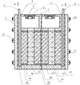
Fig. 6 is a sectional view of bipolar lead-acid accumulator of the present utility model.
Accompanying drawing explanation
Positive electrode copper sheet 1; Cover plate 2; Fixed screw 3; Positive electrode lead flake 4; The cover plate 5 of positive electrode side; Safety valve 6; Air chamber 7; Negative electrode lead flake 8; Negative electrode copper sheet 9; The cover plate 10 of negative electrode side; Negative plate 11; The insulating barrier 12 of negative electrode side; The second battery case 13; Second partition 14; The positive plate 15 of double polarity plate; Double polarity plate 16; The first dividing plate 17; The first battery case 18; Positive plate 19; The insulating barrier 20 of positive electrode; Plastic frame 21; Grid cloth 22; The negative plate 23 of double polarity plate; Steam vent 24.
Embodiment
Below in conjunction with the drawings and specific embodiments, the utility model is described further.
Embodiment mono-
As shown in Figure 1, the present embodiment is a kind of dynamical bipolar lead-acid accumulator, and this storage battery adopts a double polarity plate, comprises positive ends electrode, negative polarity termination electrode and is located at the double polarity plate between positive ends electrode, negative polarity termination electrode; Positive ends electrode and negative polarity termination electrode comprise electrode copper sheet and electrode lead flake, electrode copper sheet tin welding is on electrode lead flake, the fusing point of common scolding tin and plumbous fusing point approach, therefore can not adopt conventional soldering tin material, in the present embodiment, the material of this welding adopts slicker solder eutectic material, and accurately controls welding temperature greatly about 280 degree left and right.In order to guarantee can not assemble because of top electronics, thereby electric current is excessive, thereby cause solder joint over hot melting that electrode copper sheet and electrode lead flake are disconnected, the utility model is close to electrode lead flake one side by electrode copper sheet, the positive electrode lead flake opposite side dress positive polarity pole plate of positive ends electrode, the negative electrode lead flake opposite side dress negative polarity pole plate of negative polarity termination electrode, and the bottom level of the bottom of electrode copper sheet and this electrode lead flake alignment, the top of electrode copper sheet is as the link of external load, this is arranged so that electric current just can rely on electrode copper sheet conduction from bottom, while certainly specifically implementing, the bottom level of the bottom of electrode copper sheet and this electrode lead flake can not line up yet, for example the bottom of electrode copper sheet is slightly higher than the bottom of electrode lead flake, in a word, the bottom of electrode copper sheet is stretched as much as possible downwards.In addition, electrode lead flake separates electrode copper sheet and the compartment that carries out chemical reaction, thereby has guaranteed that electrode copper sheet can not pollute battery, has improved again the conductive effectiveness of whole battery.As shown in Figure 4 and Figure 5, above-mentioned electrode stereotype is bonded with plastic pad electrode pad one side is housed, described plastic pad comprises plastic grid and is attached to the lead plaster on plastic grid, the grid cloth that described plastic grid comprises plastic frame and surrounded by plastic frame, by the design of grid cloth, realized the better stereotype of performance has been applied in the middle of lead acid accumulator, traditional needs due to painting lead plaster have been abandoned in this design, have to give up the stereotype that performance is better, thereby must use the mentality of designing of the lead alloy of rigidity.Because grid cloth is more soft, if adopt the lead alloy of rigidity, its grid cloth and rigidity lead alloy be on the contrary by out-of-flatness, the bonding that grid cloth and lead alloy cannot be coincide like this, and stereotype quality is softness relatively, can more coincide bonding with the grid cloth that scribbles lead plaster.
Thereby double polarity plate forms the negative plate of double polarity plate at positive ends electrode opposite side design negative polarity electrode, thereby at negative polarity termination electrode opposite side design straight polarity electrode, form the positive plate of double polarity plate; Between positive ends electrode and the negative plate of double polarity plate, between the positive plate of double polarity plate and negative polarity termination electrode, be respectively provided with the hard board partition of absorption electrolyte, the same structure that adopts above-mentioned stereotype adhered plastics pole plate of this double polarity plate, be that anodal plastic pad is to adhere to anode diachylon on plastic grid, negative pole plastic pad is to adhere to cathode lead plaster on plastic grid.
Adopt the structure of stereotype adhered plastics pole plate, make the relatively traditional storage battery of the design's double polarity plate thinner, lighter weight, its double polarity plate can reach the above thickness of 2.0cm, under unit volume, the hard board partition that adsorbs electrolyte can be thickened, generally can reach the thickness of 1.7cm, thereby the design's specific energy is high a lot of compared with like product.As shown in Figure 6, the design is respectively provided with air chamber at the top of described each hard board partition, this air chamber connects the top of whole hard board partition, described each air chamber is isolated mutually, the gas outlet of each air chamber is staggered, top at each air chamber is respectively provided with safety valve, described safety valve upper end is provided with cover plate, for example adopt the structure of valve control Capsule, when air pressure inside reaches a certain restriction, can back down valve control Capsule and carry out automatic deflation, when internal gas is discharged into a certain degree, valve control Capsule automatic-sealed once more.
Be the cover plate of positive polarity side and the cover plate of negative polarity side in this example.This design has completely cut off the impact of different compartments's coefficient of expansion, and because air chamber is independent, in process of manufacture, the step of its acid adding is also easy, has improved the qualification rate of whole product.Certainly, adopting an other advantage of structure of stereotype adhered plastics pole plate is that hard board partition thickens, and the required precision in generating process, the position of air chamber being arranged is reduced, thereby has reduced the cost of whole battery.
Outside above-mentioned battery, surrounding is wrapped up by cover plate, between described straight polarity electrode and described cover plate, be respectively provided with insulating barrier between described negative polarity electrode and described cover plate, the for example insulating barrier of the positive electrode in this example and the insulating barrier of negative electrode, in the bottom of this battery, battery case is set, for example the first battery case and the second battery case in figure; Described stereotype all inserts after this battery case, encapsulation process is carried out in its coupling part, as shown in Figure 2, cover plate is fixed on described insulating barrier by fixed screw, described fixed screw adopts primary screw, and arrange closely, this fixing design has guaranteed the hermetic seal of whole battery, and the space availability ratio of cover plate is higher.
Embodiment bis-
As shown in Figure 3, it is the storage battery that 10 compartments form, this battery comprises straight polarity electrode, negative polarity electrode and be located at described straight polarity electrode, 9 double polarity plates between negative polarity electrode, wherein, electrode line electrode, the structure of negative polarity electrode is similar with embodiment mono-, 9 double polarity plates according to the contrary setting principle of polarity are: positive polarity utmost point electrode is housed negative polarity electrode corresponding setting is mutually housed, be the 1st double polarity plate negative electrode one side of positive ends electrode pair, one side of the 1st double polarity plate positive electrode is just to the 2nd double polarity plate negative electrode one side ... the like, until the positive anticathode termination electrode of side negative electrode one side of last double polarity plate positive electrode.Each double polarity plate has been divided into 10 compartments by whole batteries, what specifically other structures of this batteries all can reference example one, do not repeat them here.In this structure, the steam vent of the air chamber of each compartment is that arrange left and right, like this setting party acid adding in production technology.
Embodiment tri-
The manufacturing step of the electrode plate grid in lead acid accumulator: first adopt common grid cloth, preferably, the material of this grid cloth adopts acidproof, corrosion-resistant material, for grid cloth softness, its grid cloth often adopts very thin filament to be made into, existing employing plastics cannot the very thin rib of injection moulding place, in this grid cloth surrounding, carry out injection moulding, form plastic frame, thereby this plastic frame forms plastic grid for grid cloth is shaped, and then be coated with cream on this plastic grid, the operation such as solidify and dry, follow-up painting cream, the operation such as solidify and dry identical with existing common process.Finally this plastic pad and stereotype bond, in bipolar lead-acid accumulator, two end electrodes is a plastic pad and a stereotype, middle plate is an anodal plastic pad and again with one negative pole plastic pad of a stereotype, so-called anodal plastic pad is on plastic grid, to be coated with anode diachylon, and so-called negative pole plastic pad is on plastic grid, to be coated with cathode lead plaster.In unipolarity battery, two end electrodes is that a plastic pad and a stereotype are bonded, and middle plate is that positive plate is bonded by two anodal plastic pad and a stereotype, and middle negative plate is bonded by two negative pole plastic pad and a stereotype.Adopt the structure of grid cloth and plastic frame, form plastic grid, and then on this plastic grid, be coated with lead plaster, thereby and then this plastic pad and stereotype are bondd and form electrode pad, this design has successfully realized stereotype has been applied in the structure of lead acid accumulator.
The above is only preferred implementation of the present utility model; it should be pointed out that for those skilled in the art, without departing from the concept of the premise utility; can also make some improvements and modifications, these improvements and modifications also should be considered as in the utility model protection range.
Claims (8)
1. a dynamical bipolar lead-acid accumulator, is characterized in that, comprises positive ends electrode, negative polarity termination electrode and is located at the double polarity plate between described positive ends electrode, negative polarity termination electrode; Described positive ends electrode is equipped with positive polarity pole plate, and described negative polarity termination electrode is equipped with negative polarity pole plate; Described double polarity plate is equipped with negative polarity electrode at positive ends electrode opposite side, at described negative polarity termination electrode opposite side, straight polarity electrode is housed; Between the negative polarity electrode of described positive ends electrode and described double polarity plate, between the straight polarity electrode of described double polarity plate and described negative polarity termination electrode, be respectively provided with the hard board partition of absorption electrolyte, top at described each hard board partition is respectively provided with air chamber, described each air chamber is isolated mutually, top at each air chamber is respectively provided with safety valve, and described safety valve upper end is provided with cover plate.
2. a dynamical bipolar lead-acid accumulator, it is characterized in that, comprise positive ends electrode, negative polarity termination electrode and be located at least one double polarity plate that be provided with between described positive ends electrode, negative polarity termination electrode, described positive ends electrode dress positive polarity pole plate, described negative polarity termination electrode dress negative polarity pole plate, described double polarity plate one side is equipped with negative polarity electrode, opposite side is equipped with straight polarity electrode, described double polarity plate arranges according to the contrary setting principle of polarity, described double polarity plate is divided into independently battery chamber by battery components, the hard board partition of absorption electrolyte is set between the straight polarity electrode of each battery chamber and negative polarity electrode, top at hard board partition arranges air chamber, top at air chamber is respectively provided with safety valve, described safety valve upper end is provided with cover plate, the air chamber of described each battery chamber is isolated mutually, the contrary setting principle of described polarity is: positive polarity utmost point electrode is housed negative polarity electrode corresponding setting is mutually housed.
3. according to the bipolar lead-acid accumulator described in claim 1 or 2, it is characterized in that, described straight polarity electrode or negative polarity electrode comprise electrode copper sheet and electrode lead flake, described electrode copper sheet is close to described electrode lead flake one side, the bottom level alignment of the bottom of described electrode copper sheet and described electrode lead flake, the top of described electrode copper sheet is as the link of external load; The electrode lead flake opposite side dress positive polarity pole plate of described straight polarity electrode, the electrode lead flake opposite side dress negative polarity pole plate of described negative polarity electrode.
4. according to the bipolar lead-acid accumulator described in claim 1 or 2, it is characterized in that, cover plate comprises described straight polarity electrode and described negative polarity electrode, between described straight polarity electrode and described cover plate, be respectively provided with insulating barrier between described negative polarity electrode and described cover plate.
5. according to the bipolar lead-acid accumulator described in claim 1 or 2, it is characterized in that, electrode lead flake one side is bonded with plastic pad, described plastic pad comprises plastic grid and is attached to the lead plaster on plastic grid, the grid cloth that described plastic grid comprises plastic frame and surrounded by plastic frame.
6. according to the bipolar lead-acid accumulator described in claim 1 or 2, it is characterized in that, described double polarity plate comprises middle conduction stereotype and is bonded in respectively anodal plastic pad and the negative pole plastic pad of this centre conduction stereotype one side, described plastic pad comprises plastic grid and is attached to the lead plaster on plastic grid, the grid cloth that described plastic grid comprises plastic frame and surrounded by plastic frame, described anodal plastic pad is to adhere to anode diachylon on plastic grid, and described negative pole plastic pad is to adhere to cathode lead plaster on plastic grid.
7. according to the bipolar lead-acid accumulator described in claim 1 or 2, it is characterized in that, described electrode copper sheet tin welding is on described electrode lead flake, and the material of described tin welding is slicker solder eutectic.
8. according to the bipolar lead-acid accumulator described in claim 1 or 2, it is characterized in that, cover plate is fixed on insulating barrier by fixed screw, and described fixed screw adopts primary screw, and arranges closely.
Priority Applications (1)
| Application Number | Priority Date | Filing Date | Title |
|---|---|---|---|
| CN201320661973.0U CN203589165U (en) | 2013-10-24 | 2013-10-24 | Bipolar lead-acid storage battery with high efficiency |
Applications Claiming Priority (1)
| Application Number | Priority Date | Filing Date | Title |
|---|---|---|---|
| CN201320661973.0U CN203589165U (en) | 2013-10-24 | 2013-10-24 | Bipolar lead-acid storage battery with high efficiency |
Publications (1)
| Publication Number | Publication Date |
|---|---|
| CN203589165U true CN203589165U (en) | 2014-05-07 |
Family
ID=50587029
Family Applications (1)
| Application Number | Title | Priority Date | Filing Date |
|---|---|---|---|
| CN201320661973.0U Expired - Fee Related CN203589165U (en) | 2013-10-24 | 2013-10-24 | Bipolar lead-acid storage battery with high efficiency |
Country Status (1)
| Country | Link |
|---|---|
| CN (1) | CN203589165U (en) |
Cited By (2)
| Publication number | Priority date | Publication date | Assignee | Title |
|---|---|---|---|---|
| CN103531853A (en) * | 2013-10-24 | 2014-01-22 | 林子进 | High performance bipolar lead-acid storage battery |
| CN107706426A (en) * | 2017-10-16 | 2018-02-16 | 谢凡 | Bipolar lead-acid accumulator |
-
2013
- 2013-10-24 CN CN201320661973.0U patent/CN203589165U/en not_active Expired - Fee Related
Cited By (3)
| Publication number | Priority date | Publication date | Assignee | Title |
|---|---|---|---|---|
| CN103531853A (en) * | 2013-10-24 | 2014-01-22 | 林子进 | High performance bipolar lead-acid storage battery |
| CN103531853B (en) * | 2013-10-24 | 2016-04-13 | 林子进 | A kind of dynamical bipolar lead-acid accumulator |
| CN107706426A (en) * | 2017-10-16 | 2018-02-16 | 谢凡 | Bipolar lead-acid accumulator |
Similar Documents
| Publication | Publication Date | Title |
|---|---|---|
| CN103208633B (en) | Horizon battery and manufacturing method thereof | |
| CN103682476B (en) | Battery | |
| CN208637537U (en) | A kind of solid state battery of low interfacial resistance | |
| CN107204408A (en) | A kind of full lug quadrate lithium battery and preparation method thereof | |
| CN103531852B (en) | A kind of bipolar lead-acid accumulator | |
| WO2017181618A1 (en) | Modular multi-cell battery | |
| CN103531819B (en) | Pole plate, middle plate and its manufacture method for lead-acid accumulator | |
| CN102945929B (en) | Multi-pole-set battery and manufacture method thereof | |
| CN109309257A (en) | A kind of battery and cell production method | |
| CN203589165U (en) | Bipolar lead-acid storage battery with high efficiency | |
| CN101202356A (en) | Long life high capacity bipolar-type pole plate lead acid battery for electric automobile | |
| CN207530032U (en) | A kind of lithium ion cell polar ear of high sealing liquid-leakage preventing | |
| CN203491339U (en) | Polar plate and middle polar plate for lead-acid storage battery | |
| CN103531853B (en) | A kind of dynamical bipolar lead-acid accumulator | |
| CN203589170U (en) | Bipolar lead-acid storage battery | |
| CN102013511A (en) | Flexible packed cylindrical battery | |
| CN209232828U (en) | Lithium ion battery with aluminum shell and its shell and its top cover | |
| CN203895566U (en) | Cylindrical flexibly-packaged lithium titanate battery | |
| CN212874703U (en) | Soft packet of lithium ion battery group of integrated into one piece's interior cluster | |
| EP2894644A1 (en) | High-power electric double-layer capacitor | |
| CN201174397Y (en) | Column type lead accumulator | |
| CN210640289U (en) | Energy-saving and environment-friendly battery | |
| CN110783641A (en) | Less-maintenance valve-controlled alkaline secondary battery | |
| CN209709087U (en) | A kind of lamination type electric core | |
| CN218677263U (en) | High-internal-serial-number bipolar battery |
Legal Events
| Date | Code | Title | Description |
|---|---|---|---|
| C14 | Grant of patent or utility model | ||
| GR01 | Patent grant | ||
| CF01 | Termination of patent right due to non-payment of annual fee | ||
| CF01 | Termination of patent right due to non-payment of annual fee |
Granted publication date: 20140507 Termination date: 20211024 |