CN203585956U - Double-light-go-out-face LED wall lamp - Google Patents
Double-light-go-out-face LED wall lamp Download PDFInfo
- Publication number
- CN203585956U CN203585956U CN201320740510.3U CN201320740510U CN203585956U CN 203585956 U CN203585956 U CN 203585956U CN 201320740510 U CN201320740510 U CN 201320740510U CN 203585956 U CN203585956 U CN 203585956U
- Authority
- CN
- China
- Prior art keywords
- lampshade
- base plate
- opening
- base
- luminous plaque
- Prior art date
- Legal status (The legal status is an assumption and is not a legal conclusion. Google has not performed a legal analysis and makes no representation as to the accuracy of the status listed.)
- Expired - Lifetime
Links
- 238000007789 sealing Methods 0.000 claims abstract description 24
- 239000000853 adhesive Substances 0.000 claims description 3
- 230000001070 adhesive effect Effects 0.000 claims description 3
- 239000011505 plaster Substances 0.000 claims description 3
- 230000005855 radiation Effects 0.000 claims description 3
- 239000012780 transparent material Substances 0.000 claims description 3
- 230000000694 effects Effects 0.000 abstract description 11
- 238000004134 energy conservation Methods 0.000 abstract 1
- 230000007613 environmental effect Effects 0.000 abstract 1
- 238000007598 dipping method Methods 0.000 description 5
- 238000010586 diagram Methods 0.000 description 4
- 239000000463 material Substances 0.000 description 3
- 238000005516 engineering process Methods 0.000 description 2
- 210000002435 tendon Anatomy 0.000 description 2
- VYPSYNLAJGMNEJ-UHFFFAOYSA-N Silicium dioxide Chemical compound O=[Si]=O VYPSYNLAJGMNEJ-UHFFFAOYSA-N 0.000 description 1
- 230000008878 coupling Effects 0.000 description 1
- 238000010168 coupling process Methods 0.000 description 1
- 238000005859 coupling reaction Methods 0.000 description 1
- 238000000354 decomposition reaction Methods 0.000 description 1
- 238000005265 energy consumption Methods 0.000 description 1
- 238000009434 installation Methods 0.000 description 1
- 238000000034 method Methods 0.000 description 1
- 238000012986 modification Methods 0.000 description 1
- 230000004048 modification Effects 0.000 description 1
- 238000007639 printing Methods 0.000 description 1
- 239000000741 silica gel Substances 0.000 description 1
- 229910002027 silica gel Inorganic materials 0.000 description 1
- 239000013589 supplement Substances 0.000 description 1
Images


Landscapes
- Arrangement Of Elements, Cooling, Sealing, Or The Like Of Lighting Devices (AREA)
- Non-Portable Lighting Devices Or Systems Thereof (AREA)
Abstract
The utility model relates to a double-light-go-out-face LED wall lamp. The LED wall lamp comprises a lamp body and a base, wherein the base is sleeved with the lamp body, the lamp body comprises a lampshade and a light transmitting cover, and the light transmitting cover is tightly attached to the inner wall of the lampshade; a lampshade groove is formed in the front of the lampshade, a first lampshade opening is formed in the lampshade groove, and a second lampshade opening is formed in the bottom of the lampshade; the base comprises a sealing ring, an LED light-emitting plate, a reflection sheet, a base plate and a driver, and the sealing ring, the LED light-emitting plate, the reflection sheet and the driver are all installed on the inner side of the base plate and located in the light transmitting cover; the sealing ring is fixed to the near periphery of the inner side of the base plate; the reflection sheet is matched with the LED light-emitting plate, and the front face of the LED light-emitting plate faces towards the first lampshade opening and the second lampshade opening. The LED wall lamp is simple and more reasonable in structural design, two light go-out faces are designed, and therefore the light go-out effect is good, and the wall lamp is beautiful; the LED wall lamp is good in sealing effect, waterproof and suitable for being installed outdoors; because the LED light-emitting plate is adopted, the LED wall lamp is long in service life and safe, and the energy conservation and environmental protection purposes can be achieved at the same time.
Description
Technical field
The utility model relates to a kind of pair of exiting surface LED wall lamp, is mainly used in being arranged on Indoor environment, outer wall, belongs to a kind of lighting.
Background technology
In prior art, conventional wall lamp conventionally by hanging feet plate, lampshade, in cover, cloche etc. form, the wall lamp of this structure is by screw, each parts to be fixed together when mounted, this just makes the surface of light fixture inevitably leave too much head of screw, affected the aesthetic property of light fixture integral body, and waterproof sealing effect is poor; Meanwhile, general wall lamp is used conventional light source, and energy consumption grade is high, not energy-conserving and environment-protective.
Utility model content
The purpose of this utility model is to overcome above shortcomings in prior art, and provide, a kind of structural design is more reasonable, lighting effect is better, two exiting surface LED wall lamps of energy-conserving and environment-protective.
The technical scheme in the invention for solving the above technical problem is: this pair of exiting surface LED wall lamp comprises lamp body and base, described lamp body is enclosed within on base, it is characterized in that: described lamp body comprises lampshade and diffuser, described diffuser and lampshade are connected and fixed and are close to the inwall of lampshade; Before described lampshade, be provided with a lampshade groove, on this lampshade groove, be provided with lampshade opening one, the bottom of described lampshade is provided with lampshade opening two, and the opening court of lampshade opening one and lampshade opening two oliquely downward; The part of the corresponding lampshade opening one of described diffuser and lampshade opening two is that transparent material is made; Described base comprises sealing ring, LED luminous plaque, reflector plate, base plate and driver, and described sealing ring, LED luminous plaque, reflector plate and driver are installed in the inner side of base plate and are positioned at diffuser; Described sealing ring is fixed on the nearly surrounding in inner side of base plate; Described reflector plate coordinates with LED luminous plaque, LED luminous plaque just facing to lampshade opening one and lampshade opening two.The diffuser at lampshade opening one and lampshade opening two places exposes light-permeable, form two exiting surfaces of lamp, LED luminous plaque be obliquely installed with reflector plate and have a certain degree mutually (approach mutually vertical), both cooperatively interact and make light that LED luminous plaque sends through the reflection of reflector plate, thereby make lampshade opening one and lampshade opening two, are two effective bright dippings of exiting surface of lamp; When lamp body is overlapped to upper bed-plate, diffuser is enclosed within on base plate and compresses, and sealing ring is squeezed and reaches the effect of sealing, waterproof; LED luminous plaque surface temperature is low, and the temperature of close to sources position only has 50 about degree, little on the impact of materials'use life-span, the zero accident accident risk of burning, and LED light efficiency is good, energy-conserving and environment-protective.
Lampshade described in the utility model and diffuser front is circle and side is triangle; Described base plate is circular, and described reflector plate is semicircle.The global design of lamp is preferably circle, is designed beautifully, and also can select square or other shapes; The shape phase coadaptation of lampshade, diffuser, base plate and reflector plate; Whole lamp is installed main luminous and reflection part in below bright dipping and middle and lower part, so the bottom of lamp is thick, top is thin, makes volume smaller and more exquisite.
Lampshade groove described in the utility model is circular arc and the bottom above that is positioned at lampshade; Described lampshade opening one and lampshade opening two are circular arc.Lampshade groove, lampshade opening one and the shape of lampshade opening two and the global shape of lamp mate.
On lampshade described in the utility model, be provided with lampshade boss, described diffuser is fixed on lampshade boss.The design of lampshade boss can arbitrarily not moved relative to lampshade diffuser, good fixing effect.
The nearly surrounding in inner side of base plate described in the utility model is provided with the circumference boss of annular, and described sealing ring is enclosed within outside circumference boss.The structure of circumference boss is used for fixed seal ring better.
The lower inside of base plate described in the utility model is provided with the reflector plate fixing lug boss of cylindrical structure, and the nearly lower end of reflector plate has through hole, and reflector plate fixing lug boss snaps in the through hole of reflector plate reflector plate is fixed on base plate; The middle inside of described base plate is provided with LED luminous plaque fixing lug boss, and this LED luminous plaque fixing lug boss tilts perpendicular to base plate and lower surface, and LED luminous plaque is arranged on the lower surface of LED luminous plaque fixing lug boss.Reflector plate fixing lug boss and LED luminous plaque fixing lug boss can make reflector plate and LED luminous plaque tilt to fix better, and the convex tendon that the back of reflector plate preferably has on base plate supports.
The inner side of base plate described in the utility model is provided with groove, and driver is fixed in this groove by heat radiation adhesive plaster.Groove one driver coupling, driver can arbitrarily not slide, and guarantees the normal work of lamp.
Angle between the front of LED luminous plaque described in the utility model and the front of reflector plate is greater than 90 degree.
The both sides of lamp body described in the utility model are fixed with screw and base respectively; The both sides of described base plate are respectively arranged with bayonet socket, and two described screws pass the both sides of lamp body and snap in the bayonet socket of base.Screw with make between lamp body and base fixation reliable coordinating of bayonet socket; Screw only has two, does not affect the overall appearance of lamp.
The utility model compared with prior art, has the following advantages and effect: structural design simply and more reasonable, has designed two exiting surfaces, and bright dipping is effective and more attractive in appearance; Good sealing effect, waterproof, be applicable to being arranged on outdoor; Adopt LED luminous plaque, long service life and safety, energy-conserving and environment-protective simultaneously.
Accompanying drawing explanation
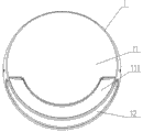
Fig. 1 is the main TV structure schematic diagram of the utility model embodiment.
Fig. 2 is the left TV structure schematic diagram of the utility model embodiment.
Fig. 3 is the decomposition texture schematic diagram of the utility model embodiment.
Fig. 4 is the sectional structure schematic diagram of Fig. 2.
In figure: lamp body 1, base 2, screw 3, lampshade 11, diffuser 12, lampshade groove 111, lampshade opening 1, lampshade opening 2 113, lampshade boss 114, sealing ring 21, LED luminous plaque 22, reflector plate 23, base plate 24, driver 25, circumference boss 241, bayonet socket 242, reflector plate fixing lug boss 243, LED luminous plaque fixing lug boss 244, groove 245.
The specific embodiment
Below in conjunction with accompanying drawing and by embodiment, the utility model is described in further detail.
Embodiment.
Referring to Fig. 1-Fig. 4, the present embodiment comprises lamp body 1 and base 2, and lamp body 1 comprises lampshade 11 and diffuser 12, and base 2 comprises sealing ring 21, LED luminous plaque 22, reflector plate 23, base plate 24 and driver 25.
In the present embodiment, base 2 is fixed by screw and metope, and lamp body 1 is enclosed within on base 2 and both sides are fixed with screw 3 and base 2 respectively.
In the present embodiment, lampshade 11 and diffuser 12 are circle and are from the side up-small and down-big triangle, are provided with lampshade boss 114 on lampshade 11, and diffuser 12 is fixed on lampshade boss 114 and is close to the inwall of lampshade 11; Lampshade 11 is provided with the lampshade groove 111 of a circular arc, and this lampshade groove 111 is positioned at lampshade 11 bottom above; On the sidewall of lampshade groove 111, be provided with lampshade opening 1, the bottom of lampshade 11 is provided with lampshade opening 2 113, lampshade opening 1 and lampshade opening 2 113 are through hole, and lampshade opening 1 and lampshade opening 2 113 are seen from front and be circular arc and opening towards oliquely downward; Diffuser 12 whole clearings, expose and printing opacity at two places of the corresponding lampshade opening 1 of diffuser 12 and lampshade opening 2 113, is two exiting surfaces of whole lamp.
In the present embodiment, sealing ring 21, LED luminous plaque 22, reflector plate 23 and driver 25 are installed in the inner side of base plate 24 and are positioned at diffuser 12; Base plate 24 is circular.
In the present embodiment, the inner side of base plate 24 is provided with circumference boss 241, and this circumference boss 241 is positioned at the nearly surrounding of base plate 24 and is annular; Sealing ring 21 is enclosed within outside circumference boss 241, and when covering lamp body 1, diffuser 12 is enclosed within on base plate 24 and press seal circle 21, thereby reaches the effect of sealing, waterproof; The both sides of base plate 24 are respectively arranged with the bayonet socket 242 that 242, two screws of bayonet socket 3 pass the both sides of lamp body 1 and snap in base 2, make lamp body 1 fixing with base 2; The lower inside of base plate 24 is provided with reflector plate fixing lug boss 243, the boss that this reflector plate fixing lug boss 243 is cylindrical structure, reflector plate 23 has through hole for semicircle and nearly circular arc top (being nearly lower end), and reflector plate fixing lug boss 243 snaps in the through hole of reflector plate 23 reflector plate 23 is fixed on base plate 24; The middle inside of base plate 24 is provided with LED luminous plaque fixing lug boss 244, and this LED luminous plaque fixing lug boss 244 is perpendicular to base plate 24, and LED luminous plaque 22 is arranged on the lower surface of LED luminous plaque fixing lug boss 244; The inner side of base plate 24 is provided with groove 245, and driver 25 is fixed in this groove 245 by heat radiation adhesive plaster.
In the present embodiment, reflector plate 23 is positioned at the below of LED luminous plaque 22 and presses close to base plate 24, and reflector plate 23 is supported jack-up by the convex tendon on base plate 24 turns forward the top of reflector plate 23; The lower surface of LED luminous plaque fixing lug boss 244 tilts, and the front portion of LED luminous plaque 22 is inclined upwardly; LED luminous plaque 22 just facing to oblique below and be partial to the place ahead direction of lampshade opening 1 and lampshade opening 2 113 (towards), reflector plate 23 just facing to tiltedly the place ahead deflection below, angle between the front of the front of LED luminous plaque 22 and reflector plate 23 is greater than 90 degree, by the LED luminous plaque 22 and the reflector plate 23 that are obliquely installed, the light that LED luminous plaque 22 sends, through the reflection of reflector plate, can make two effective bright dippings of exiting surface of lamp.
When the utility model is installed, the installation in advance of the accessory of lamp body 1 and base 2, first base 2 is screwed in body of wall, connect after circuit, lamp body 1 is enclosed within on base 2, tighten two screws 3 of both sides, sealing ring 21 is compacted, thereby reach the effect of sealing, waterproof, can effectively prevent that rainwater from entering in light fixture, make lamp be applicable to being arranged on outdoor (on the exterior wall of building); Switch on power, LED luminous plaque 22 is luminous, and through the reflection of reflector plate 23, by the position bright dipping of corresponding lampshade opening 1 and lampshade opening 2 113 on diffuser 12, lamp has two exiting surfaces, thereby makes the illuminating effect of lamp better and more attractive in appearance.
It is transparent that diffuser 12 of the present utility model also can be designed to two places of only corresponding lampshade opening 1 and lampshade opening 2 113, and other parts are opaque, cost-saved; Diffuser 12 whole for the advantage of transparent material be process, easy to make.
The utility model adopts three 2W LED luminous plaques 22, power 2W, and lumen value reaches 180lm, and can reach more than 30,000 hours service life.
LED technology in the utility model is same as the prior art or close, the material of sealing ring 21 used is conventional sealed material (for example silica gel), it is also prior art that the power supply of lamp, circuit connect, and these are all the basic general knowledge that those of ordinary skills know, and no longer describes in detail herein.
In the utility model Fig. 3, the upside of base plate 24 is the inner side of base plate 24, and in Fig. 2 and Fig. 4, the right side is front, Zuo Weihou.
By foregoing description, those skilled in the art can implement.
In addition, it should be noted that, above example has been made comparatively detailed description to the utility model, but these descriptions are not to restriction of the present utility model, and the utility model is not limited to concrete structure and the description of above-mentioned example.The utility model person of ordinary skill in the field can make various modifications or supplements or adopt similar mode to substitute described specific embodiment; only otherwise depart from structure of the present utility model or surmount this scope as defined in the claims, all should belong to protection domain of the present utility model.
Claims (9)
1. two exiting surface LED wall lamps, comprise lamp body and base, and described lamp body is enclosed within on base, it is characterized in that: described lamp body comprises lampshade and diffuser, and described diffuser and lampshade are connected and fixed and are close to the inwall of lampshade; Before described lampshade, be provided with a lampshade groove, on this lampshade groove, be provided with lampshade opening one, the bottom of described lampshade is provided with lampshade opening two, and the opening court of lampshade opening one and lampshade opening two oliquely downward; The part of the corresponding lampshade opening one of described diffuser and lampshade opening two is that transparent material is made; Described base comprises sealing ring, LED luminous plaque, reflector plate, base plate and driver, and described sealing ring, LED luminous plaque, reflector plate and driver are installed in the inner side of base plate and are positioned at diffuser; Described sealing ring is fixed on the nearly surrounding in inner side of base plate; Described reflector plate coordinates with LED luminous plaque, LED luminous plaque just facing to lampshade opening one and lampshade opening two.
2. according to claim 1 pair of exiting surface LED wall lamp, is characterized in that: described lampshade and diffuser front is circle and side is triangle; Described base plate is circular, and described reflector plate is semicircle.
3. according to claim 2 pair of exiting surface LED wall lamp, is characterized in that: described lampshade groove is circular arc and the bottom above that is positioned at lampshade; Described lampshade opening one and lampshade opening two are circular arc.
4. according to claim 1 and 2 pair of exiting surface LED wall lamp, is characterized in that: on described lampshade, be provided with lampshade boss, described diffuser is fixed on lampshade boss.
5. according to claim 1 pair of exiting surface LED wall lamp, is characterized in that: the nearly surrounding in inner side of described base plate is provided with the circumference boss of annular, and described sealing ring is enclosed within outside circumference boss.
6. according to claim 1 pair of exiting surface LED wall lamp, it is characterized in that: the lower inside of described base plate is provided with the reflector plate fixing lug boss of cylindrical structure, the nearly lower end of reflector plate has through hole, and reflector plate fixing lug boss snaps in the through hole of reflector plate reflector plate is fixed on base plate; The middle inside of described base plate is provided with LED luminous plaque fixing lug boss, and this LED luminous plaque fixing lug boss tilts perpendicular to base plate and lower surface, and LED luminous plaque is arranged on the lower surface of LED luminous plaque fixing lug boss.
7. according to claim 1 pair of exiting surface LED wall lamp, is characterized in that: the inner side of described base plate is provided with groove, and driver is fixed in this groove by heat radiation adhesive plaster.
8. according to the two exiting surface LED wall lamps described in claim 1 or 6, it is characterized in that: the angle between the front of described LED luminous plaque and the front of reflector plate is greater than 90 degree.
9. according to claim 1 pair of exiting surface LED wall lamp, is characterized in that: the both sides of described lamp body are fixed with screw and base respectively; The both sides of described base plate are respectively arranged with bayonet socket, and two described screws pass the both sides of lamp body and snap in the bayonet socket of base.
Priority Applications (1)
| Application Number | Priority Date | Filing Date | Title |
|---|---|---|---|
| CN201320740510.3U CN203585956U (en) | 2013-11-22 | 2013-11-22 | Double-light-go-out-face LED wall lamp |
Applications Claiming Priority (1)
| Application Number | Priority Date | Filing Date | Title |
|---|---|---|---|
| CN201320740510.3U CN203585956U (en) | 2013-11-22 | 2013-11-22 | Double-light-go-out-face LED wall lamp |
Publications (1)
| Publication Number | Publication Date |
|---|---|
| CN203585956U true CN203585956U (en) | 2014-05-07 |
Family
ID=50583868
Family Applications (1)
| Application Number | Title | Priority Date | Filing Date |
|---|---|---|---|
| CN201320740510.3U Expired - Lifetime CN203585956U (en) | 2013-11-22 | 2013-11-22 | Double-light-go-out-face LED wall lamp |
Country Status (1)
| Country | Link |
|---|---|
| CN (1) | CN203585956U (en) |
Cited By (1)
| Publication number | Priority date | Publication date | Assignee | Title |
|---|---|---|---|---|
| CN107883356A (en) * | 2017-11-03 | 2018-04-06 | 江门市云达灯饰有限公司 | A kind of inlet wire plate of ground footlight |
-
2013
- 2013-11-22 CN CN201320740510.3U patent/CN203585956U/en not_active Expired - Lifetime
Cited By (1)
| Publication number | Priority date | Publication date | Assignee | Title |
|---|---|---|---|---|
| CN107883356A (en) * | 2017-11-03 | 2018-04-06 | 江门市云达灯饰有限公司 | A kind of inlet wire plate of ground footlight |
Similar Documents
| Publication | Publication Date | Title |
|---|---|---|
| CN203585959U (en) | Bi-directional LED wall lamp | |
| CN204853181U (en) | Novel LED down lamp | |
| CN203585957U (en) | LED double-head reflector lamp | |
| CN205102008U (en) | LED projection lamp | |
| CN204176532U (en) | LED solar energy wall lamp | |
| CN202835209U (en) | Stainless steel underwater light-emitting diode (LED) lamp shell | |
| CN201779579U (en) | Solar movable lawn lamp | |
| CN202091980U (en) | A high-power LED solar lamp | |
| CN202101079U (en) | Traditional light source arc-shaped wall lamp | |
| CN204176444U (en) | A kind of LED wall lamp | |
| CN203585955U (en) | Turning LED wall lamp | |
| CN202546577U (en) | Solar energy LED (light emitting diode) point light source | |
| CN201242111Y (en) | LED outdoor lighting lamp with adjustable illumination angle | |
| CN203586057U (en) | Double-head solar LED spotlight | |
| CN206055379U (en) | A kind of LED garden lamp | |
| CN206488216U (en) | A multi-functional flat panel floodlight | |
| CN205535341U (en) | A special underwater light for fountains | |
| CN206176155U (en) | LED projection lamp | |
| CN205208317U (en) | LED lamp | |
| CN219473487U (en) | Novel LED spotlight | |
| CN203586059U (en) | Led solar lamp | |
| CN220540934U (en) | Novel solar energy ceiling lamp | |
| CN202915238U (en) | Light-emitting diode (LED) solar lamp | |
| CN204268104U (en) | LED solar energy lantern | |
| CN201724012U (en) | Bar-shaped triple-prevention LED lamp |
Legal Events
| Date | Code | Title | Description |
|---|---|---|---|
| C14 | Grant of patent or utility model | ||
| GR01 | Patent grant | ||
| CX01 | Expiry of patent term |
Granted publication date: 20140507 |
|
| CX01 | Expiry of patent term |