CN203573235U - Fixing device for computer fan - Google Patents
Fixing device for computer fan Download PDFInfo
- Publication number
- CN203573235U CN203573235U CN201320795303.8U CN201320795303U CN203573235U CN 203573235 U CN203573235 U CN 203573235U CN 201320795303 U CN201320795303 U CN 201320795303U CN 203573235 U CN203573235 U CN 203573235U
- Authority
- CN
- China
- Prior art keywords
- fan
- computer
- bottom plate
- spring
- fixed plate
- Prior art date
- Legal status (The legal status is an assumption and is not a legal conclusion. Google has not performed a legal analysis and makes no representation as to the accuracy of the status listed.)
- Expired - Fee Related
Links
Landscapes
- Cooling Or The Like Of Electrical Apparatus (AREA)
Abstract
计算机风扇固定装置,它涉及计算机零部件技术领域,它包含固定板(1)、风扇(2)、底板(3)、弹簧(4)、计算机内支架(5)、卡接扳手(6)和连接接口(7);固定板(1)的上部设置有风扇(2),固定板(1)的下部设置有底板(3),底板(3)与固定板(1)之间的四个角处设置有弹簧(4),底板(3)的两侧均设置有卡接扳手(6),底板(3)通过卡接扳手(6)卡接在计算机内支架(5)上,固定板(1)的一侧设置有连接接口(7)。它方便安装风扇,方便拆卸,节省时间,且其下部设置有弹簧,延长风扇的使用寿命。
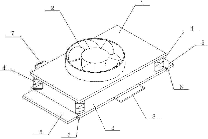
A fixing device for a computer fan, which relates to the technical field of computer components, includes a fixing plate (1), a fan (2), a bottom plate (3), a spring (4), a computer inner bracket (5), a clamping wrench (6) and The connection interface (7); the upper part of the fixed plate (1) is provided with a fan (2), the lower part of the fixed plate (1) is provided with a bottom plate (3), and the four corners between the bottom plate (3) and the fixed plate (1) A spring (4) is arranged at the place, and both sides of the bottom plate (3) are provided with snap-in spanners (6), the bottom plate (3) is clipped on the computer inner bracket (5) through the snap-in spanners (6), and the fixed plate ( 1) One side is provided with a connection interface (7). It is convenient to install and disassemble the fan, saving time, and the lower part is provided with a spring to prolong the service life of the fan.
Description
技术领域 technical field
本实用新型涉及计算机零部件技术领域,具体涉及一种计算机风扇固定装置。 The utility model relates to the technical field of computer components, in particular to a fixing device for a computer fan.
背景技术 Background technique
计算机部件中大量使用集成电路。众所周知,高温是集成电路的大敌。高温不但会导致系统运行不稳,使用寿命缩短,甚至有可能使某些部件烧毁。导致高温的热量不是来自计算机外,而是计算机内部,或者说是集成电路内部。散热器的作用就是将这些热量吸收,然后发散到机箱内或者机箱外,保证计算机部件的温度正常。多数散热器通过和发热部件表面接触,吸收热量,再通过各种方法将热量传递到远处,比如机箱内的空气中,然后机箱将这些热空气传到机箱外,完成计算机的散热。 Integrated circuits are heavily used in computer components. As we all know, high temperature is the enemy of integrated circuits. High temperature will not only lead to unstable operation of the system, shorten the service life, and may even burn some components. The heat that causes high temperature does not come from outside the computer, but from inside the computer, or inside the integrated circuit. The function of the radiator is to absorb the heat and then dissipate it inside or outside the case to ensure that the temperature of the computer components is normal. Most heat sinks absorb heat by contacting the surface of the heat-generating components, and then transfer the heat to a distant place through various methods, such as the air in the chassis, and then the chassis transfers the hot air to the outside of the chassis to complete the cooling of the computer.
计算机的散热装置大多是风扇散热,目前大多数计算机的散热风扇都是使用螺钉固定在计算机机箱的内部,如果在工作时散热风扇出现故障需要先将服务器停机,但是大多数的计算机服务器是不可以轻易停机的,而且维修或者替换散热风扇需要打开机箱,比较浪费时间,而且计算机运行时,风扇会一直抖动,缩短风扇的使用寿命。 The heat dissipation device of the computer is mostly fan heat dissipation. At present, the heat dissipation fan of most computers is fixed inside the computer case with screws. If the heat dissipation fan fails during work, the server needs to be shut down first, but most computer servers cannot It is easy to shut down, and repairing or replacing the cooling fan requires opening the case, which is a waste of time, and when the computer is running, the fan will vibrate all the time, shortening the service life of the fan.
发明内容 Contents of the invention
本实用新型的目的是提供一种计算机风扇固定装置,它方便安装风扇,方便拆卸,节省时间,且其下部设置有弹簧,延长风扇的使用寿命。 The purpose of the utility model is to provide a fixing device for a computer fan, which is convenient for fan installation and disassembly, saves time, and the lower part is provided with a spring to prolong the service life of the fan.
为了解决背景技术所存在的问题,本实用新型是采用以下技术方案:它包含固定板1、风扇2、底板3、弹簧4、计算机内支架5、卡接扳手6和连接接口7;固定板1的上部设置有风扇2,固定板1的下部设置有底板3,底板3与固定板1之间的四个角处设置有弹簧4,底板3的两侧均设置有卡接扳手6,底板3通过卡接扳手6卡接在计算机内支架5上,固定板1的一侧设置有连接接口7。 In order to solve the existing problems of the background technology, the utility model adopts the following technical solutions: it includes a fixed plate 1, a fan 2, a bottom plate 3, a spring 4, a computer inner bracket 5, a clamping wrench 6 and a connection interface 7; the fixed plate 1 The upper part of the fan 2 is provided, the bottom of the fixed plate 1 is provided with a bottom plate 3, the four corners between the bottom plate 3 and the fixed plate 1 are provided with springs 4, and both sides of the bottom plate 3 are provided with snap-in wrenches 6, and the bottom plate 3 A connection interface 7 is provided on one side of the fixing plate 1 through the clamping wrench 6 being clamped on the computer inner support 5 .
所述的底板3的外侧设置有把手8。当需要拿出风扇时,扳动卡接扳手,然后拖动把手就可以轻松的取出风扇。 A handle 8 is provided on the outer side of the base plate 3 . When you need to take out the fan, pull the clip wrench, and then drag the handle to take out the fan easily.
本实用新型具有以下有益效果:它方便安装风扇,方便拆卸,节省时间,且其下部设置有弹簧,延长风扇的使用寿命。 The utility model has the following beneficial effects: it is convenient to install and disassemble the fan, saves time, and the lower part is provided with a spring to prolong the service life of the fan.
附图说明: Description of drawings:
图1为本实用新型的结构示意图。 Fig. 1 is the structural representation of the utility model.
具体实施方式: Detailed ways:
参看图1,本具体实施方式采用以下技术方案:它包含固定板1、风扇2、底板3、弹簧4、计算机内支架5、卡接扳手6和连接接口7;固定板1的上部设置有风扇2,固定板1的下部设置有底板3,底板3与固定板1之间的四个角处设置有弹簧4,底板3的两侧均设置有卡接扳手6,底板3通过卡接扳手6卡接在计算机内支架5上,固定板1的一侧设置有连接接口7。 Referring to Fig. 1, the present embodiment adopts the following technical solutions: it includes a fixed plate 1, a fan 2, a bottom plate 3, a spring 4, a computer inner support 5, a clip wrench 6 and a connection interface 7; the upper part of the fixed plate 1 is provided with a fan 2. The lower part of the fixed plate 1 is provided with a bottom plate 3, the four corners between the bottom plate 3 and the fixed plate 1 are provided with springs 4, and both sides of the bottom plate 3 are provided with snap-in wrenches 6, and the bottom plate 3 is connected by the snap-in wrench 6 It is clamped on the computer inner bracket 5 , and one side of the fixed plate 1 is provided with a connection interface 7 .
所述的底板3的外侧设置有把手8。当需要拿出风扇时,扳动卡接扳手,然后拖动把手就可以轻松的取出风扇。 A handle 8 is provided on the outer side of the base plate 3 . When you need to take out the fan, you can easily take out the fan by pulling the snap-on wrench and then dragging the handle.
本具体实施方式方便安装风扇,方便拆卸,节省时间,且其下部设置有弹簧,延长风扇的使用寿命。 This specific embodiment is convenient for installing and disassembling the fan, saving time, and the lower part is provided with a spring to prolong the service life of the fan.
Claims (2)
Priority Applications (1)
| Application Number | Priority Date | Filing Date | Title |
|---|---|---|---|
| CN201320795303.8U CN203573235U (en) | 2013-12-06 | 2013-12-06 | Fixing device for computer fan |
Applications Claiming Priority (1)
| Application Number | Priority Date | Filing Date | Title |
|---|---|---|---|
| CN201320795303.8U CN203573235U (en) | 2013-12-06 | 2013-12-06 | Fixing device for computer fan |
Publications (1)
| Publication Number | Publication Date |
|---|---|
| CN203573235U true CN203573235U (en) | 2014-04-30 |
Family
ID=50540959
Family Applications (1)
| Application Number | Title | Priority Date | Filing Date |
|---|---|---|---|
| CN201320795303.8U Expired - Fee Related CN203573235U (en) | 2013-12-06 | 2013-12-06 | Fixing device for computer fan |
Country Status (1)
| Country | Link |
|---|---|
| CN (1) | CN203573235U (en) |
-
2013
- 2013-12-06 CN CN201320795303.8U patent/CN203573235U/en not_active Expired - Fee Related
Similar Documents
| Publication | Publication Date | Title |
|---|---|---|
| CN102999062A (en) | Switch cabinet internal temperature control system | |
| CN204189121U (en) | The adjustable multifunctional notebook computer heat sink of position of fan | |
| CN203369035U (en) | Fan fixing structure and power supply employing same | |
| CN202133950U (en) | Cooling base with slidable fan | |
| CN202257430U (en) | CPU Cooler Fan Fixing Bracket Compatible with Fans of Different Sizes | |
| CN204990152U (en) | Use cooling system on industry flat board / embedded computer | |
| CN201926969U (en) | Multifunctional notebook radiator | |
| CN206322094U (en) | A kind of computer host box rapid heat radiation device | |
| CN206018343U (en) | A kind of LED illumination device with radiator fan | |
| CN203259960U (en) | Computer heat-radiating device | |
| CN204206716U (en) | Semiconductor refrigeration constant temperature control device | |
| CN202916751U (en) | Streaming media thin client | |
| CN105807874A (en) | Double-fan radiator used for computer | |
| CN203217453U (en) | A cooling backplane | |
| CN203706116U (en) | Cooling fin fixing device | |
| CN203241904U (en) | A low power consumption cloud computer cooling system | |
| CN204028794U (en) | A kind of heat-radiating chassis for computer | |
| CN206339923U (en) | A kind of notebook PC radiator | |
| CN202461837U (en) | Electric heat-dissipating energy-saving welding machine | |
| CN204129639U (en) | A kind of active fan assembly of efficient reduction board chip temperature | |
| CN204943904U (en) | A kind of radiator structure being applied to water heater | |
| CN202166951U (en) | Hard disk seat with heat dissipation structure in computer case | |
| CN203259958U (en) | Laptop cooler | |
| CN211557794U (en) | Heat radiator of Ethernet module | |
| CN202677287U (en) | Built-in PCIE (Peripheral Component Interface Express) baffle sheet |
Legal Events
| Date | Code | Title | Description |
|---|---|---|---|
| C14 | Grant of patent or utility model | ||
| GR01 | Patent grant | ||
| CF01 | Termination of patent right due to non-payment of annual fee |
Granted publication date: 20140430 Termination date: 20141206 |
|
| EXPY | Termination of patent right or utility model |