CN203572417U - Gauge structure of transition connecting plate of vehicle roof and front side frame - Google Patents
Gauge structure of transition connecting plate of vehicle roof and front side frame Download PDFInfo
- Publication number
- CN203572417U CN203572417U CN201320761153.9U CN201320761153U CN203572417U CN 203572417 U CN203572417 U CN 203572417U CN 201320761153 U CN201320761153 U CN 201320761153U CN 203572417 U CN203572417 U CN 203572417U
- Authority
- CN
- China
- Prior art keywords
- connecting plate
- transition connecting
- block
- roof
- simulation
- Prior art date
- Legal status (The legal status is an assumption and is not a legal conclusion. Google has not performed a legal analysis and makes no representation as to the accuracy of the status listed.)
- Expired - Fee Related
Links
- 230000007704 transition Effects 0.000 title claims abstract description 30
- 230000000630 rising effect Effects 0.000 claims description 3
- 238000001514 detection method Methods 0.000 abstract description 5
- 238000000034 method Methods 0.000 abstract description 5
- 238000004088 simulation Methods 0.000 abstract 8
- 238000012512 characterization method Methods 0.000 description 2
- 238000010586 diagram Methods 0.000 description 1
Images

Landscapes
- A Measuring Device Byusing Mechanical Method (AREA)
Abstract
The utility model provides a gauge structure of a transition connecting plate of a vehicle roof and front side frame, and aims to make a detection process of the transition connecting plate of the vehicle roof and front side frame to be simple, short in period, high in efficiency, and high in accuracy. The gauge structure of the transition connecting plate of the vehicle roof and front side frame includes a bottom plate; three corners of the bottom plate are respectively provided with a benchmark sleeve; an upper end face of the bottom plate is provided with a simulation block; the periphery of the simulation block is provide with a skirt edge structure; the skirt edge structure of the simulation block is internally a simulation surface; the simulation surface from front to back is an arc surface which gradually rises in transition; the middle side of the simulation surface is convex; the simulation surface is provided with a positioning convex block which protrudes outside; the convex thickness of the positioning convex block is 3mm; the inner surface of the transition connecting plate of the vehicle roof and front side frame under a detection condition presses tightly an outer end face of the positioning convex block at a corresponding position; and a pressing pliers bracket is respectively arranged outside the bottom plate corresponding to the front and rear end position inside and outside the simulation block.
Description
Technical field
The utility model relates to the technical field of auto parts and components cubing structure, is specially the cubing structure of the transition connecting plate of a kind of roof and toe lateral frame.
Background technology
The detection of the transition connecting plate of existing car roof and toe lateral frame, it detects separately data by cubing to each position, then judge that with the numerical value contrast of standard whether the transition connecting plate of this car roof and toe lateral frame is qualified, in comparison process due to measuring error, the detection data that record by cubing also need trickle finishing, the complex process of its detection, and the cycle is long, efficiency is low, and error is larger.
Summary of the invention
For the problems referred to above, the utility model provides the cubing structure of the transition connecting plate of a kind of roof and toe lateral frame, and it makes the characterization processes of transition connecting plate of car roof and toe lateral frame simple, the cycle is short, efficiency is high, and accuracy is high.
The cubing structure of the transition connecting plate of a kind of roof and toe lateral frame, it is characterized in that: it comprises base plate, the position, wherein three angles of described base plate is respectively arranged with standard sleeve, the upper surface of described base plate is provided with simulated block, the periphery of described simulated block is with skirt border structure, the inside of the skirt border structure of described simulated block is falseface, described falseface is the cambered surface rising from the transition gradually of A-P, the middle side epirelief of described falseface, on described falseface, be provided with the locating convex block of evagination, the evagination thickness of described locating convex block is 3mm, the inside surface of the transition connecting plate of the roof under detected state and toe lateral frame presses the outer face of the locating convex block of correspondence position, the inner side of described simulated block, the front end in outside, the outside of the corresponding described base plate of back-end location is respectively arranged with a pressing tongs support, the bottom of each described pressing tongs support is anchored on described base plate, the top of described pressing tongs support connects corresponding pressing tongs by rotating shaft, the lower surface of described pressing tongs press-fits in the upper surface of the transition connecting plate correspondence position of described roof and toe lateral frame, the front end of the middle side epirelief position of described simulated block, rear end is provided with the register pin of epirelief corresponding to the position of positioning hole of the transition connecting plate of described roof and toe lateral frame, it also comprises gap go-no go gauge, the butt diameter of described gap go-no go gauge is 4.5mm, taper end diameter is 1.5mm.
Adopt after the utility model, its transition connecting plate of detected roof and toe lateral frame need be placed in simulated block falseface, by register pin, locate, pressing tongs afterwards overturns, then by gap go-no go gauge, detect, whether the physical dimension of transition connecting plate of judging detected roof and toe lateral frame is qualified, it makes the characterization processes of transition connecting plate of car roof and toe lateral frame simple, the cycle is short, efficiency is high, and accuracy is high.
Accompanying drawing explanation
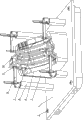
Fig. 1 is stereographic map structural representation of the present utility model;
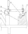
Fig. 2 is the transition connecting plate of locating convex block, roof and toe lateral frame, the mounting structure schematic diagram of pressing tongs;
Fig. 3 is the structural representation of gap of the present utility model go-no go gauge.
Embodiment
See Fig. 1~Fig. 3, it comprises base plate 1, the position, wherein three angles of base plate 1 is respectively arranged with standard sleeve 2, the upper surface of base plate 1 is provided with simulated block 3, the periphery of simulated block 3 is with skirt border structure 4, the inside of the skirt border structure 4 of simulated block 3 is falseface, falseface is the cambered surface rising from the transition gradually of A-P, the middle side epirelief 5 of falseface, on falseface, be provided with the locating convex block 6 of evagination, the evagination thickness of locating convex block 6 is 3mm, the inside surface of the transition connecting plate 7 of the roof under detected state and toe lateral frame presses the outer face of the locating convex block 6 of correspondence position, the inner side of simulated block 3, the outside of the corresponding base plate 1 in position, front-end and back-end in outside is respectively arranged with a pressing tongs support 8, the bottom of each pressing tongs support 8 is anchored on base plate 1, the top of pressing tongs support 8 connects corresponding pressing tongs 9 by rotating shaft, the lower surface of pressing tongs 9 press-fits in the upper surface of transition connecting plate 7 correspondence positions of roof and toe lateral frame, the front end of middle side epirelief 5 positions of simulated block 3, rear end is provided with the register pin 10 of epirelief corresponding to the position of positioning hole of the transition connecting plate 7 of roof and toe lateral frame, it also comprises gap go-no go gauge 11, the butt diameter of gap go-no go gauge 11 is 4.5mm, taper end diameter is 1.5mm.
Claims (1)
1. the cubing structure of the transition connecting plate of a roof and toe lateral frame, it is characterized in that: it comprises base plate, the position, wherein three angles of described base plate is respectively arranged with standard sleeve, the upper surface of described base plate is provided with simulated block, the periphery of described simulated block is with skirt border structure, the inside of the skirt border structure of described simulated block is falseface, described falseface is the cambered surface rising from the transition gradually of A-P, the middle side epirelief of described falseface, on described falseface, be provided with the locating convex block of evagination, the evagination thickness of described locating convex block is 3mm, the inside surface of the transition connecting plate of the roof under detected state and toe lateral frame presses the outer face of the locating convex block of correspondence position, the inner side of described simulated block, the front end in outside, the outside of the corresponding described base plate of back-end location is respectively arranged with a pressing tongs support, the bottom of each described pressing tongs support is anchored on described base plate, the top of described pressing tongs support connects corresponding pressing tongs by rotating shaft, the lower surface of described pressing tongs press-fits in the upper surface of the transition connecting plate correspondence position of described roof and toe lateral frame, the front end of the middle side epirelief position of described simulated block, rear end is provided with the register pin of epirelief corresponding to the position of positioning hole of the transition connecting plate of described roof and toe lateral frame, it also comprises gap go-no go gauge, the butt diameter of described gap go-no go gauge is 4.5mm, taper end diameter is 1.5mm.
Priority Applications (1)
| Application Number | Priority Date | Filing Date | Title |
|---|---|---|---|
| CN201320761153.9U CN203572417U (en) | 2013-11-28 | 2013-11-28 | Gauge structure of transition connecting plate of vehicle roof and front side frame |
Applications Claiming Priority (1)
| Application Number | Priority Date | Filing Date | Title |
|---|---|---|---|
| CN201320761153.9U CN203572417U (en) | 2013-11-28 | 2013-11-28 | Gauge structure of transition connecting plate of vehicle roof and front side frame |
Publications (1)
| Publication Number | Publication Date |
|---|---|
| CN203572417U true CN203572417U (en) | 2014-04-30 |
Family
ID=50540145
Family Applications (1)
| Application Number | Title | Priority Date | Filing Date |
|---|---|---|---|
| CN201320761153.9U Expired - Fee Related CN203572417U (en) | 2013-11-28 | 2013-11-28 | Gauge structure of transition connecting plate of vehicle roof and front side frame |
Country Status (1)
| Country | Link |
|---|---|
| CN (1) | CN203572417U (en) |
-
2013
- 2013-11-28 CN CN201320761153.9U patent/CN203572417U/en not_active Expired - Fee Related
Similar Documents
| Publication | Publication Date | Title |
|---|---|---|
| CN103630020A (en) | Gauge structure for engine compartment vertical plate | |
| CN103630048A (en) | Checking fixture structure of front-wall middle side sheet metal component | |
| CN203572362U (en) | Checking fixture structure of front engine cover plate reinforcing plate | |
| CN203572416U (en) | Gauge structure of front door inner plate reinforced piece | |
| CN203657652U (en) | Gauge structure of connecting plate between rear bumper and vehicle frame | |
| CN203811067U (en) | Testing fixture structure for rear bumper | |
| CN203657702U (en) | Automobile front bumper detection tool structure | |
| CN203518928U (en) | Needle bed base flatness detection apparatus | |
| CN203534435U (en) | Detection tool structure of reinforcement plate of lifting door wedge | |
| CN103630052A (en) | Gauge structure of lifting-gate inner-plate lower reinforcing plate | |
| CN203572411U (en) | Checking fixture structure of trunk lateral positioning reinforcing plate | |
| CN203534438U (en) | Detection tool structure of front camber beam of roof | |
| CN203534401U (en) | Gauge structure of bottom backboard | |
| CN203657647U (en) | Detection device structure for front crossbeam reinforcing connecting rod | |
| CN203534461U (en) | Detection device structure of upper B pillar reinforcing plate assembly | |
| CN203572384U (en) | Gauge structure of inner connecting plate of engine side wall | |
| CN203534429U (en) | Detection tool structure of reinforcement plate of lifting door hinge | |
| CN203534431U (en) | Detection tool structure of reinforcement elements at bottom part of seat | |
| CN103644820A (en) | Gauge structure of transition connecting plate of vehicle roof and front portion side frame | |
| CN203572369U (en) | Checking fixture structure of side wall skin reinforcement plate | |
| CN203534439U (en) | Detection tool structure of lower connection board of front wall | |
| CN203534489U (en) | Detection tool structure of reinforcement plate of lifting door lock | |
| CN203534436U (en) | Detection tool structure of guiding reinforcement plate at side part of rear wall | |
| CN203572409U (en) | Detecting fixture structure for lift gate inner plate lower reinforcing plate | |
| CN203534490U (en) | Detection tool structure of internal connection board of vehicle door |
Legal Events
| Date | Code | Title | Description |
|---|---|---|---|
| C14 | Grant of patent or utility model | ||
| GR01 | Patent grant | ||
| CF01 | Termination of patent right due to non-payment of annual fee |
Granted publication date: 20140430 Termination date: 20141128 |
|
| EXPY | Termination of patent right or utility model |