CN203553431U - Socket - Google Patents
Socket Download PDFInfo
- Publication number
- CN203553431U CN203553431U CN201320688322.0U CN201320688322U CN203553431U CN 203553431 U CN203553431 U CN 203553431U CN 201320688322 U CN201320688322 U CN 201320688322U CN 203553431 U CN203553431 U CN 203553431U
- Authority
- CN
- China
- Prior art keywords
- socket
- box body
- opening
- box
- lid
- Prior art date
- Legal status (The legal status is an assumption and is not a legal conclusion. Google has not performed a legal analysis and makes no representation as to the accuracy of the status listed.)
- Expired - Lifetime
Links
- 238000000034 method Methods 0.000 description 5
- 230000004308 accommodation Effects 0.000 description 1
- 230000009286 beneficial effect Effects 0.000 description 1
- 230000007547 defect Effects 0.000 description 1
- 230000007812 deficiency Effects 0.000 description 1
- 238000005516 engineering process Methods 0.000 description 1
Images

Landscapes
- Connector Housings Or Holding Contact Members (AREA)
Abstract
The utility model discloses a socket which comprises a box. The box is provided with an opening, a box cover which can close the opening is arranged on the box body, a socket body is arranged in the opening of the box, and a gap exists between the socket body and at least one sidewall of the box. According to the utility model, the socket body is arranged in the box, so that equipment which is inserted into the socket body and power wires thereof are not exposed, so that use is safer.
Description
Technical field
The utility model relates to a kind of socket.
Background technology
Socket, claims again supply socket, and combined socket and switch has referred to the insertable seat of one or more circuit connections, by it, can insert various wiring, is convenient to connect with other circuit.Supply socket is the electric equipment that power interface is provided for household electrical appliance, is also in design of residence, to use more electrical accessory, and it and people's life have ten close relationships.
When the equipment that need be connected with socket inserts described socket, equipment itself is exposed to socket outside, the state that makes this equipment be easy to touch in children, very dangerous.And equipment is exposed to very not attractive in appearance of outside.Based on above-mentioned defect, be necessary existing socket to improve.
Summary of the invention
For the deficiencies in the prior art, the utility model provides a kind of socket, when equipment inserts socket, provides the spatial accommodation of the power line that holds described interventional instrument and this equipment.Prevent the potential safety hazard of bringing that interventional instrument and power line thereof expose.
The utility model is achieved by the following technical solution: a kind of socket, comprise that box body, described box body are provided with opening, the lid of closing described opening is set on box body, in the opening of described box body, jack body is set, described jack body at least and between the sidewall of described box body one side has gap.
In technique scheme, described jack body is fixedly installed on described box body one side.
In technique scheme, on described box body, be provided with the opening of drawing for plug cord.
In technique scheme, described lid is rotatably connected on box body.
In technique scheme, the described lid place of being rotationally connected is positioned at and described jack body homonymy.
In technique scheme, in described interstitial site, draw-in groove is set.
The utlity model has following beneficial effect: the utility model is by being arranged at jack body in box body, therefore insert equipment on described jack body and the power line of equipment thereof and can not be exposed to outside, make to use more safe.
Accompanying drawing explanation
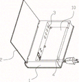
Fig. 1 is perspective view of the present utility model.
Fig. 2 is the structural representation of the utility model embodiment 2.
Fig. 3 is the structural representation of the utility model embodiment 2 other directions.
Embodiment
Below in conjunction with accompanying drawing, the utility model is described in further detail, embodiment 1: referring to Fig. 1, a kind of socket: comprise that box body 1, described box body 1 are roughly rectangular shape (similar with books shape), while therefore using, socket does not need pendulum on table top, can as placing books, socket be put on bookshelf.And when socket is not used, electric wire is directly accommodated in box body inside, very attractive in appearance and not taking up room.
On described box body 1, opening 10 is set, at the interior jack body 3 that arranges of described box opening 10, described jack body 3 at least and between the sidewall of described box body 1 one sides has gap, and this gap is for holding the equipment that inserts described socket, as mobile phone, charger for mobile phone, electric wire etc.
Described jack body 3 is fixedly installed on described box body 1 one sides, guarantees that the gap forming between the sidewall of described jack body 3 and described box body one side can reach maximum.And described lid 2 is rotatably connected on box body 1.And described lid 2 places of being rotationally connected are positioned at and described jack body 3 homonymies.
On described box body 1, be provided with the opening 4 of drawing for plug cord, for the plug cord for described jack body 3, pass through, guarantee that, when lid 2 covers, plug cord can not lean on box body 1 and lid 2 surfaces.
Embodiment 2: referring to Fig. 2 to Fig. 3, in described interstitial site, draw-in groove 5 is set, when as the charging of the mini-plant such as mobile phone, mobile phone etc. can be arranged in described draw-in groove 5, use very convenient; In described box body 1 position, two side, offer groove 6, when charging as panel computer (label W in Fig. 3), because panel computer volume is larger, cannot put into box body, therefore can open lid 2, make panel computer one side lean lid 2, opposite side is arranged in two grooves 6.In real time example 2 all the other with embodiment 1.
Claims (6)
1. a socket, it is characterized in that: comprise that box body (1), described box body (1) are provided with opening (10), on box body (1), be provided with the lid (2) for closing described opening (10), in the opening (10) of described box body (1), jack body (3) is set, described jack body (3) at least and between the sidewall of described box body (1) one side has gap.
2. a kind of socket as claimed in claim 1, is characterized in that: described jack body (3) is fixedly installed on described box body (1) one side.
3. a kind of socket as claimed in claim 1, is characterized in that: on described box body (1), be provided with the opening (4) of drawing for plug cord.
4. a kind of socket as claimed in claim 1, is characterized in that: described lid (2) is rotatably connected on box body (1).
5. a kind of socket as claimed in claim 1, is characterized in that: described lid (2) place of being rotationally connected is positioned at and described jack body (3) homonymy.
6. a kind of socket as claimed in claim 1, is characterized in that: in described interstitial site, draw-in groove (5) is set.
Priority Applications (1)
| Application Number | Priority Date | Filing Date | Title |
|---|---|---|---|
| CN201320688322.0U CN203553431U (en) | 2013-11-04 | 2013-11-04 | Socket |
Applications Claiming Priority (1)
| Application Number | Priority Date | Filing Date | Title |
|---|---|---|---|
| CN201320688322.0U CN203553431U (en) | 2013-11-04 | 2013-11-04 | Socket |
Publications (1)
| Publication Number | Publication Date |
|---|---|
| CN203553431U true CN203553431U (en) | 2014-04-16 |
Family
ID=50471503
Family Applications (1)
| Application Number | Title | Priority Date | Filing Date |
|---|---|---|---|
| CN201320688322.0U Expired - Lifetime CN203553431U (en) | 2013-11-04 | 2013-11-04 | Socket |
Country Status (1)
| Country | Link |
|---|---|
| CN (1) | CN203553431U (en) |
-
2013
- 2013-11-04 CN CN201320688322.0U patent/CN203553431U/en not_active Expired - Lifetime
Similar Documents
| Publication | Publication Date | Title |
|---|---|---|
| CN103579818A (en) | Socket | |
| CN204407594U (en) | A kind of dust-proof electrical outlets | |
| CN103840332B (en) | Safety socket | |
| CN202977836U (en) | Annular socket | |
| CN203826716U (en) | Safety socket | |
| CN203503896U (en) | Modular socket for the blind | |
| CN202068019U (en) | Multifunctional concealed power socket | |
| CN203242809U (en) | Safety outer cover with foldable-handle type support clamp for socket | |
| CN202602008U (en) | Safety socket | |
| CN106207577A (en) | A kind of one side diplopore safety socket receiver | |
| CN206461143U (en) | A kind of three-dimensional multipurpose socket | |
| CN203387220U (en) | Wireless charging device | |
| CN202772380U (en) | Combined socket | |
| CN204103101U (en) | Indoor insert row safety protecting box | |
| CN203085816U (en) | Multifunctional safe socket | |
| CN202957632U (en) | Vehicle battery power supply device | |
| CN203660152U (en) | Socket | |
| CN201689951U (en) | Battery recharging device for mobile cells | |
| CN210779191U (en) | Layered hidden socket | |
| CN204179349U (en) | A kind of moisture-proof socket | |
| CN203225383U (en) | Novel storage box | |
| CN204179369U (en) | A kind of Novel socket | |
| CN207530256U (en) | A kind of multifunction wiring board | |
| CN204205151U (en) | Portable multifunctional socket | |
| CN205377336U (en) | Universal serial bus (USB) charger |
Legal Events
| Date | Code | Title | Description |
|---|---|---|---|
| C14 | Grant of patent or utility model | ||
| GR01 | Patent grant | ||
| CX01 | Expiry of patent term |
Granted publication date: 20140416 |
|
| CX01 | Expiry of patent term |