CN203528724U - Brake device used for mechanical disc brake of bicycle - Google Patents
Brake device used for mechanical disc brake of bicycle Download PDFInfo
- Publication number
- CN203528724U CN203528724U CN201320695625.5U CN201320695625U CN203528724U CN 203528724 U CN203528724 U CN 203528724U CN 201320695625 U CN201320695625 U CN 201320695625U CN 203528724 U CN203528724 U CN 203528724U
- Authority
- CN
- China
- Prior art keywords
- brake
- armshaft
- hole
- rotor
- ball grooves
- Prior art date
- Legal status (The legal status is an assumption and is not a legal conclusion. Google has not performed a legal analysis and makes no representation as to the accuracy of the status listed.)
- Withdrawn - After Issue
Links
Images



Landscapes
- Braking Arrangements (AREA)
Abstract
The utility model relates to a brake device used for a mechanical disc brake of a bicycle. The brake device comprises a double-shaft connecting rod, wherein the upper part of the double-shaft connecting rod is provided with a brake cable connecting part; two sides of the brake cable connecting part are respectively connected with a first shaft arm and a second shaft arm both in same structure; a first shaft arm hole and a second shaft arm hole are formed in the lower ends of the first shaft arm and the second shaft arm respectively; a first brake component and a second brake component in the same structure are arranged in the first shaft arm hole and the second shaft arm hole respectively. The brake device is arranged in the mechanical disc brake and can realize bilateral braking, so that a disc plate is not easy to deform, a brake pad is not easy to abrade, and a good braking effect is achieved. A bilateral braking effect with an oil pressure is achieved, and oil leakage is avoided. The brake device is low in cost, simple and practical in structure.
Description
Technical field
The utility model belongs to bicycle disc brakes field, relates in particular to a kind of brake equipment for bicycle mechanical disc brake.
Background technology
Bicycle disc brakes is comprised of the brake gear at a braking disc being connected with wheel and disc edge. during brake, thereby promote brake facing, make it to clamp braking disc generation braking effect.At present, according to the mode of braking action, distinguish, or divide with the medium of start brake facing clamping disc, the one, brake cable, the one, oil.Mechanical disc brake, leans on the pulling force of brake cable by the brake facing in clamp, rub and clamp disc, produces braking effect.Hydraulic disc, take fluid as medium, draws brake making piston compression fluid, and pressure is from the straight-through clamp of oil pipe, thereby the piston in promotion clamp drives brake facing clamping disc.
In prior art, mechanical disc brake is one side brake.Namely only have the brake facing of can extrapolating on one side to exert pressure, rub in disc, the brake facing of another side allows both sides all produce break-in effect after pushing through with the disc on opposite.Its deficiency is: disc is easily out of shape, and brake facing easily weares and teares.
Hydraulic disc mostly is bilateral braking, allows brake facing from both sides, clamp together disc.Its deficiency is: easily leakage of oil, regularly replace brake solution.
Utility model content
The purpose of this utility model is to overcome the above-mentioned weak point of existing product, and a kind of brake equipment for bicycle mechanical disc brake is provided, and this device can be realized the bilateral braking of mechanical disc brake.
The technical scheme that the utility model is realized its object employing is: a kind of brake equipment for bicycle mechanical disc brake, comprise twin shaft connecting rod, described twin shaft small end has brake cable connecting portion, and brake cable connecting portion both sides are connected with respectively the first armshaft and the second armshaft that structure is identical; The lower end of described the first armshaft and the second armshaft is respectively equipped with the first armshaft hole, the second armshaft hole; The first brake assemblies that structure is identical and the second brake assemblies are contained in respectively in the first armshaft hole and the second armshaft hole.
Described the first inner side, armshaft hole is at least provided with three the first armshaft ball grooves around.
Described the first brake assemblies comprises the first stator, clutch shaft bearing, the first ball, the first rotor successively.
In the middle of the first stator, there is the first stator hole, in the middle of clutch shaft bearing, there is clutch shaft bearing hole, in the middle of the first rotor one side, there is the first rotor axle, described the first rotor axle is at least distributed with three the first rotor ball grooves around, the first rotor axle is located in clutch shaft bearing hole, the first stator hole through the first armshaft hole more successively from the inner side of the first armshaft, and described clutch shaft bearing is contained in the clutch shaft bearing installation position in the first outside, armshaft hole.
Described the first armshaft ball grooves is that one end extends to the other end from deep to shallow, is inclined-plane transition gradually; The first rotor ball grooves is identical with the first armshaft ball grooves structure, in the first rotor ball grooves and the first armshaft ball grooves, is placed with the first ball.
Described the second brake assemblies comprises the second stator, the second bearing, the second ball, the second rotor successively; The first brake assemblies is identical with the second brake assemblies structure.
Beneficial effect: the utility model is the device of one of them the driving brake facing in bicycle mechanical disc brake pincers, uses this device to be arranged in braking clamp and can realize bilateral braking, makes disc not yielding, and brake facing is not easy to wear.Braking effect is good., can there is not oil leakage phenomenon again in the bilateral braking effect with oil pressure.Its cost is low, simple and practical.
Accompanying drawing explanation
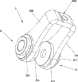
Fig. 1 is the utility model structural representation.
Fig. 2 is the utility model STRUCTURE DECOMPOSITION schematic diagram.
Fig. 3 the utility model twin shaft bar linkage structure schematic diagram.
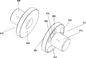
Fig. 4 the utility model the first rotor and the second rotor structure schematic diagram.
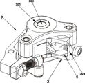
Fig. 5 is bicycle mechanical disc brake structural representation.
Fig. 6 is that bicycle mechanical disc brake is arranged on schematic diagram in disc.
Number in the figure representative: braking disc 1, bicycle mechanical disc brake 2, brake equipment 3, the first brake assemblies 4, the second brake assemblies 5, brake cable 6, twin shaft connecting rod 33, the first stator 301, the first stator hole 302, clutch shaft bearing 303, clutch shaft bearing hole 304, the first armshaft ball grooves 305, the first armshaft 306, the first armshaft hole 307, the first ball 308, the first rotor axle 309, the first rotor 310, the second rotor 311, the second rotor ball grooves 312, the second rotor shaft 313, the second ball 314, the second armshaft 315, the second bearing 316, the second stator 317, the second stator hole 318, the second bearing hole 319, the second armshaft hole 320, the second brake facing stationary plane 321, deep trouth place 322, shallow slot place 323, brake cable connecting portion 324, the second bearing installation position 325, first brake sheet stationary plane 326.
The specific embodiment
Below in conjunction with specific embodiments and the drawings, the utility model is described in further detail.
See Fig. 1-4, a kind of brake equipment for bicycle mechanical disc brake, comprises twin shaft connecting rod 33, and there is brake cable connecting portion 324 described twin shaft connecting rod 33 upper ends, and brake cable connecting portion 324 both sides are connected with respectively the first armshaft 306 and the second armshaft 315 that structure is identical; Twin shaft connecting rod 33 is for falling " U " shape in the drawings.
The lower end of described the first armshaft 306 and the second armshaft 315 is respectively equipped with the first armshaft hole 307, the second armshaft hole 320; The first brake assemblies 4 that structure is identical and the second brake assemblies 5 are contained in respectively in the first armshaft hole 307 and the second armshaft hole 320.
307 inner sides, described the first armshaft hole are at least provided with three the first armshaft ball grooves 305 around.
Described the first brake assemblies 4 comprises the first stator 301, clutch shaft bearing 303, the first ball 308, the first rotor 310 successively.
In the middle of the first stator 301, there is the first stator hole 302, in the middle of clutch shaft bearing 303, there is clutch shaft bearing hole 304, in the middle of the first rotor 310 1 sides, there is the first rotor axle 309, described the first rotor axle 309 is at least distributed with three the first rotor ball grooves around, refer to Fig. 4, the first rotor 310 is identical with the second rotor 311 structures, and the first rotor ball grooves does not draw because of angular relationship, and the first rotor ball grooves is identical with the second rotor ball grooves 312 structures.
See Fig. 1,2, the first rotor axle 309 is located in clutch shaft bearing hole 304, the first stator hole 302 through the first armshaft hole 307 more successively from the inner side of the first armshaft 306, and described clutch shaft bearing 303 is contained in the clutch shaft bearing installation position in 307 outsides, the first armshaft hole.Clutch shaft bearing installation position, because angular relationship does not draw, refers to the second bearing installation position 325 in the second armshaft hole 320 in Fig. 3.Clutch shaft bearing 303 effects are: when pulling twin shaft connecting rod 33, guarantee its stable and collimation.
Described the first armshaft ball grooves 305 extends to the other end from deep to shallow for one end, is inclined-plane transition gradually; The first rotor ball grooves is identical with the first armshaft ball grooves 305 structures, in the first rotor ball grooves and the first armshaft ball grooves 305, is placed with the first ball 308.
Described the second brake assemblies 5 comprises the second stator 317, the second bearing 316, the second ball 314, the second rotor 311 successively; The first brake assemblies 4 is identical with the second brake assemblies 5 structures.
In Fig. 3,4, the first armshaft ball grooves 305 and the second rotor ball grooves 312, extend to shallow slot place 323 from deep trouth 322, is inclined-plane transition gradually.
The first armshaft ball grooves 305 is combined with the first rotor ball grooves, forms enclosed ball grooves, and the present embodiment is three ball grooves, puts into respectively the first ball 308.
The utility model is not a complete mechanical disc brake, is an assembly that drives brake facing in mechanical disc brake.The present invention is metallic material.
And see Fig. 4,5,6, when use is of the present invention, the first stator 301 and the second stator 317 will be separately fixed in the housing of bicycle mechanical disc brake 2, fixing brake facing in the first brake sheet stationary plane 326 of the first rotor 310 and the second brake facing stationary plane 321 of the second rotor 311, during use, braking disc 1 is provided in a side of between two brake facings.
Fixing brake cable in brake cable connecting portion 324, when pulling brake cable, drive twin shaft connecting rod 33 to rotate, the first rotor 310 also can rotate thereupon, and because the first stator 301 is fixed, the first rotor 310 can make the first ball 308 move to the shallow end ball grooves on inclined-plane when rotating, like this, when the first rotor 310 is when being subject to the first ball 308 extruding, the first rotor 310 moves inward, and promotes brake facing and press braking disc.
The first stator 301 is identical with the second stator 317 structures, and the first rotor 310 is identical with the second rotor 311 structures.With this simultaneously, when another side the second rotor 311 pushes because being subject to the second ball 314, the second rotor 311 moves inward, and promotes brake facing and press braking disc, like this, just becomes bilateral braking.Bicycle mechanical disc brake concrete structure can be with reference to Chinese Patent Application No. 2013104665762, and name is called the patent application of " the two braking of bicycle mechanical disc brake ".
To those skilled in the art, obviously the invention is not restricted to the details of above-mentioned one exemplary embodiment, and in the situation that not deviating from spirit of the present invention or essential characteristic, can realize the present invention with other concrete form.Therefore, no matter from which point, all should regard embodiment as exemplary, and be nonrestrictive, scope of the present invention is limited by claims rather than above-mentioned explanation, is therefore intended to include in the present invention dropping on the implication that is equal to important document of claim and all changes in scope.Any Reference numeral in claim should be considered as limiting related claim.
Claims (1)
1. the brake equipment for bicycle mechanical disc brake, comprise twin shaft connecting rod (33), it is characterized in that: there is brake cable connecting portion (324) described twin shaft connecting rod (33) upper end, brake cable connecting portion (324) both sides are connected with respectively the first armshaft (306) and the second armshaft (315) that structure is identical; Described the first armshaft (306) is respectively equipped with the first armshaft hole (307), the second armshaft hole (320) with the lower end of the second armshaft (315); The first brake assemblies (4) that structure is identical is contained in respectively in the first armshaft hole (307) and the second armshaft hole (320) with the second brake assemblies (5);
Described the first inner side, armshaft hole (307) is at least provided with three the first armshaft ball grooves (305) around;
Described the first brake assemblies (4) comprises the first stator (301), clutch shaft bearing (303), the first ball (308), the first rotor (310) successively;
In the middle of the first stator (301), there is the first stator hole (302), in the middle of clutch shaft bearing (303), there is clutch shaft bearing hole (304), in the middle of the first rotor (310) one sides, there is the first rotor axle (309), described the first rotor axle (309) is at least distributed with three the first rotor ball grooves around, the first rotor axle (309) is located in clutch shaft bearing hole (304) from the inner side of the first armshaft (306) more successively through the first armshaft hole (307), in the first stator hole (302), described clutch shaft bearing (303) is contained in the clutch shaft bearing installation position in the first outside, armshaft hole (307),
Described the first armshaft ball grooves (305) extends to the other end from deep to shallow for one end, is inclined-plane transition gradually; The first rotor ball grooves is identical with the first armshaft ball grooves (305) structure, in the first rotor ball grooves and the first armshaft ball grooves (305), is placed with the first ball (308);
Described the second brake assemblies (5) comprises the second stator (317), the second bearing (316), the second ball (314), the second rotor (311) successively; The first brake assemblies (4) is identical with the second brake assemblies (5) structure.
Priority Applications (1)
| Application Number | Priority Date | Filing Date | Title |
|---|---|---|---|
| CN201320695625.5U CN203528724U (en) | 2013-11-06 | 2013-11-06 | Brake device used for mechanical disc brake of bicycle |
Applications Claiming Priority (1)
| Application Number | Priority Date | Filing Date | Title |
|---|---|---|---|
| CN201320695625.5U CN203528724U (en) | 2013-11-06 | 2013-11-06 | Brake device used for mechanical disc brake of bicycle |
Publications (1)
| Publication Number | Publication Date |
|---|---|
| CN203528724U true CN203528724U (en) | 2014-04-09 |
Family
ID=50414968
Family Applications (1)
| Application Number | Title | Priority Date | Filing Date |
|---|---|---|---|
| CN201320695625.5U Withdrawn - After Issue CN203528724U (en) | 2013-11-06 | 2013-11-06 | Brake device used for mechanical disc brake of bicycle |
Country Status (1)
| Country | Link |
|---|---|
| CN (1) | CN203528724U (en) |
Cited By (1)
| Publication number | Priority date | Publication date | Assignee | Title |
|---|---|---|---|---|
| CN103538672A (en) * | 2013-11-06 | 2014-01-29 | 黄国政 | Brake device used for mechanical disc brake of bicycle |
-
2013
- 2013-11-06 CN CN201320695625.5U patent/CN203528724U/en not_active Withdrawn - After Issue
Cited By (1)
| Publication number | Priority date | Publication date | Assignee | Title |
|---|---|---|---|---|
| CN103538672A (en) * | 2013-11-06 | 2014-01-29 | 黄国政 | Brake device used for mechanical disc brake of bicycle |
Similar Documents
| Publication | Publication Date | Title |
|---|---|---|
| CN203996714U (en) | A kind of double-axle rotator device for mechanical disc brake | |
| CN103538673B (en) | For the brake equipment of bicycle mechanical disc brake | |
| CN203528723U (en) | Braking device for bicycle machinery disc brake | |
| CN103538672B (en) | A kind of brake equipment for bicycle mechanical disc brake | |
| CN203528722U (en) | Double-shaft rotor device for bicycle mechanical disc brake | |
| CN203819444U (en) | Mechanical disc brake double-shaft rotor structure | |
| CN201521574U (en) | Direct-pushing type single-cylinder normally-closed brake | |
| CN201273350Y (en) | Electromagnetic friction brake | |
| CN203666894U (en) | Thread-type brake device used for bicycle mechanical disk brake | |
| CN203602304U (en) | Safety brake | |
| CN103661751B (en) | A kind of screw-type brake equipment for bicycle mechanical disc brake | |
| CN203666895U (en) | Thread type braking device for mechanical disc brake of bicycle | |
| CN103496421A (en) | Double-shaft rotor device for mechanical disc-brake of bicycle | |
| CN103482000A (en) | Bicycle double-brake mechanical disc-braking device | |
| CN103661752B (en) | For the screw-type brake equipment of bicycle mechanical disc brake | |
| CN203453333U (en) | Hydraulic clutch | |
| CN203210485U (en) | Press roll structure of flattening machine | |
| CN106954694A (en) | Multistation tea cake briquetting machine | |
| CN203395149U (en) | Device for eliminating axial force in running of helical gear shaft adopting belleville spring | |
| CN102862315B (en) | Press hydraulic clutch structure | |
| CN203528721U (en) | Mechanical anti-lock device of bicycle | |
| CN203730617U (en) | Break caliper with gap adjustment function | |
| CN2713170Y (en) | Electromagnetic anti-theft brake special for pumping unit | |
| CN202826496U (en) | Hydraulic clutch structure of press machine | |
| CN221563028U (en) | Braking device and tractor |
Legal Events
| Date | Code | Title | Description |
|---|---|---|---|
| C14 | Grant of patent or utility model | ||
| GR01 | Patent grant | ||
| AV01 | Patent right actively abandoned |
Granted publication date: 20140409 Effective date of abandoning: 20150819 |
|
| RGAV | Abandon patent right to avoid regrant |