CN203499220U - Suspension type sufficient-water plastering machine - Google Patents
Suspension type sufficient-water plastering machine Download PDFInfo
- Publication number
- CN203499220U CN203499220U CN201320575712.7U CN201320575712U CN203499220U CN 203499220 U CN203499220 U CN 203499220U CN 201320575712 U CN201320575712 U CN 201320575712U CN 203499220 U CN203499220 U CN 203499220U
- Authority
- CN
- China
- Prior art keywords
- roller
- crane
- hanger
- track
- rail bracket
- Prior art date
- Legal status (The legal status is an assumption and is not a legal conclusion. Google has not performed a legal analysis and makes no representation as to the accuracy of the status listed.)
- Expired - Fee Related
Links
- 239000000725 suspension Substances 0.000 title claims abstract description 22
- XLYOFNOQVPJJNP-UHFFFAOYSA-N water Substances O XLYOFNOQVPJJNP-UHFFFAOYSA-N 0.000 title claims abstract description 21
- 239000011505 plaster Substances 0.000 claims abstract description 40
- 239000000835 fiber Substances 0.000 claims description 20
- PXFBZOLANLWPMH-UHFFFAOYSA-N 16-Epiaffinine Natural products C1C(C2=CC=CC=C2N2)=C2C(=O)CC2C(=CC)CN(C)C1C2CO PXFBZOLANLWPMH-UHFFFAOYSA-N 0.000 claims description 17
- 239000000463 material Substances 0.000 claims description 17
- 239000003381 stabilizer Substances 0.000 claims description 15
- 244000309464 bull Species 0.000 claims description 10
- 230000003028 elevating effect Effects 0.000 claims description 8
- 238000009432 framing Methods 0.000 claims description 6
- 238000007790 scraping Methods 0.000 claims description 4
- 230000000630 rising effect Effects 0.000 description 6
- 238000000034 method Methods 0.000 description 3
- 239000011449 brick Substances 0.000 description 2
- 238000010276 construction Methods 0.000 description 2
- 238000002474 experimental method Methods 0.000 description 2
- 239000007787 solid Substances 0.000 description 2
- 238000010009 beating Methods 0.000 description 1
- 230000000694 effects Effects 0.000 description 1
- 238000005516 engineering process Methods 0.000 description 1
- 230000005484 gravity Effects 0.000 description 1
- -1 grey hopper 2 rises Substances 0.000 description 1
- 239000004615 ingredient Substances 0.000 description 1
- 239000000203 mixture Substances 0.000 description 1
- 239000011435 rock Substances 0.000 description 1
Images




Landscapes
- Conveying And Assembling Of Building Elements In Situ (AREA)
Abstract
The utility model provides a suspension type sufficient-water plastering machine which comprises a track frame. The track frame is suspended on a hanger, a lifting frame capable of moving along the track frame up and down is arranged on the track frame, a plaster tank is mounted on the side, which is far away from the hanger, of the lifting frame, two slide grooves are formed in the rear wall of the plaster tank, an overturn plaster tank cover is arranged on the top of the plaster tank, a residual plaster chamber is arranged on the upper portion of the plaster tank, a tool support capable of moving in the plaster tank up and down is arranged on the lower portion of the plaster tank, a plastering tool is placed on the tool support, and an affinity roll is positioned in the plaster tank, is horizontally arranged above the plastering tool and can move in the plaster tank up and down; two lifting chains are further arranged on the lifting frame, one end of each lifting chain is connected with the tool support, and the other end of each lifting chain is wound through the upper side of the lifting frame to be fixedly connected with the track frame. The suspension type sufficient-water plastering machine has the advantages that the plastering quality is obviously improved, plastered surfaces are perpendicular, flat and smooth, and the plastering speed and the plastering height are multiplied; plasters can be effectively adhered with wall surfaces and firmly and rigidly condensed in the wall surfaces, and the problem that plasters and a wall surface become two separate skins is solved; the suspension type sufficient-water plastering machine can be moved conveniently, is safe and stable and can be operated easily and conveniently.
Description
Technical field
The utility model belongs to construction work auxiliary equipment technical field, relates to a kind of troweling machine for brick wall surface plastering, particularly a kind of suspension type foot water troweling machine.
Background technology
Applicant had once applied for utility model patent < < suspension beating type plastering machine > > (patent No. ZL200510095909.0 on August 18th, 2005, day for announcing CN100400782, but find in experiment for many years, on probation, research, development day for announcing 2008.07.09): this stand alone type troweling machine in practical process, exist not reliable, dangerous, heavy, move the problems such as inconvenience, time-consuming, effort; In addition the moisture content in the process of plastering in ash material is absorbed by brick wall, causes grey caking property very poor, solidifies loose, not hard; After dry, ash becomes two skins with wall, cause building insecure, easily collapse, endanger very large.Also have bracing frame too high, it is indefinite in use, to rock, and easily tipping, more dangerous during Mo building external wall; When smearing interior wall, the top of a wall foundation place, because of shared by machine itself, respectively has a scraper-trough conveyer to smear less than ash etc.
Summary of the invention
For above-mentioned problems of the prior art, the utility model provides the high-caliber suspension type of a kind of high-quality foot water troweling machine, plaster vertical, straight and even, smooth, bond firm and solid, solidify hardly, room wall is difficult for collapsing; Can smear the top of a wall, foundation place, and airframe structure is simple, reasonable, light, moves leicht fallen D/A, safe and reliable.
For achieving the above object, the technical scheme that the utility model adopts is: a kind of suspension type foot water troweling machine, comprise the rail bracket hanging on hanger, hanger bottom is vertically provided with revolves screw mandrel, revolve screw mandrel lower end and be provided with by bull wheel of the electric motor driven end, revolve and on screw mandrel, be set with interior fiber tube, its inward turning silk with revolve screw mandrel and revolve silk and intermesh, while revolving screw mandrel rotation, interior fiber tube can move up and down; Interior fiber tube is connected with crane by connecting rod, and crane is installed on rail bracket, and can slide up and down along rail bracket; The side that crane deviates from hanger is provided with grey hopper, the side that ash hopper deviates from hanger does not have panel, ash hopper is respectively provided with a sliding tray towards the rear wall both sides of hanger, ash material box top is provided with the ash material case lid that can uncover, ash material upper box part is provided with residual grey chamber, and the bottom in grey hopper is provided with the knife support that can move up and down in grey hopper, is placed with plaster trowel on knife support, ash hopper upper horizontal interior, plaster trowel is provided with affine roller, and affine roller can move up and down in grey hopper; One end of two elevator chains is connected with knife support, and the other end of elevator chain is walked around with rail bracket back timber affixed from crane top top roll.
The utility model suspension type foot water troweling machine on the original basis, has carried out rationally appropriately properly improving through experiment repeatedly, and plastering quality obviously improves, and the face of plastering is vertical, straight and even, smooth, the speed of plastering with highly significantly improve; Ash bonds with wall surface, solidifies firm and solid, hardly, can not become two skins; Fuselage height reduces greatly, and fuselage weight alleviates greatly, move very convenient, safety and steady, easy and simple to handle, and automaticity is high.
Accompanying drawing explanation
Fig. 1 is the structural representation of the utility model suspension type foot water troweling machine the first embodiment.
Fig. 2 is the right view of Fig. 1.
Fig. 3 is the structural representation of knife support in the utility model the first embodiment.
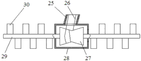
Fig. 4 is the structural representation of affine roller in the utility model suspension type foot water troweling machine.
Fig. 5 is the structural representation of the utility model suspension type foot water troweling machine the second embodiment.
Fig. 6 is the left view of Fig. 5.
Fig. 7 is an ingredient of knife support in the utility model suspension type foot water troweling machine the second embodiment.
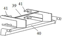
Fig. 8 is the one other component of knife support in the utility model suspension type foot water troweling machine the second embodiment.
In figure: 1. plaster trowel, 2. grey hopper, 3. affine roller, 4. hanger, 5. hanger beam, 6. elevator chain, 7. crane, 8. rise back roller, 9. stabiliser bar, 10. pull bar, 11. interior fiber tubes, 12. revolve screw mandrel, 13. rail brackets, 14. motor, 15. end bull wheels, 16. deflecting rollers, 17. knife supports, 18. connecting rods, 19. knife rest strutbeams, 20. contain leakage ash-pan, 21. dish ripping bars, 22. first track roller, 23. second track roller, 24. stabiliser bar sleeve pipes, 25. suspended tubes, 26. wire rope, 27. rollers, 28. roller boxes, 29. roller bearings, 30. scraping blades, 31. links, 32. adjustment screw, 33. track plates, 34. side levers, 35. braces, 36. head pieces, 37. hooks, 38. junction plates, 39. lifting beams, 40. roller frames, 41. baby track rollers, 42. connecting rings, 43. sliding trays.
The specific embodiment
Below in conjunction with the drawings and specific embodiments, the utility model is elaborated.
As depicted in figs. 1 and 2, the utility model troweling machine the first embodiment, comprises that the rail bracket 13 of shaped as frame, rail bracket 13 tops are provided with hook 37, and rail bracket 13 hangs on the hanger beam 5 on hanger 4 tops by linking up with 37; Rail bracket 13 tops are also provided with pull bar 10, live and be connected with hanger beam 5 in the upper end of pull bar 10, and the other end of pull bar 10 is free end; Base is established in rail bracket lower end, and base is provided with and revolves screw mandrel 12, revolves screw mandrel 12 lower ends end bull wheel 15 is installed, and end bull wheel 15 is driven by motor 14; Revolve on screw mandrel 12 and be set with interior fiber tube 11, interior fiber tube 11 can move up and down along revolving screw mandrel 12.Interior fiber tube 11 is connected with the crane 7 of frame-shaped construction by connecting rod 18, and crane 7 is installed in rail bracket 13 grooves, and can move up and down along the groove of rail bracket 13; Crane 7 tops are provided with and rise back roller 8; In crane 7 crossbeams, stabiliser bar 9 is vertically installed; The side that crane 7 deviates from hanger 4 is provided with grey hopper 2, and the side that grey hopper 2 deviates from hanger 4 does not have antetheca, and grey hopper 2 is respectively established a sliding tray 43 paralleling with stabiliser bar 9 towards the rear wall both sides of hanger 4; Ash hopper 2 tops are provided with the ash material case lid that can uncover, and grey hopper 2 tops are provided with towards the residual grey chamber 33 of hanger 4, and the bottom surface of residual grey chamber 33 is inclined-plane.Bottom in ash hopper 2 is provided with structure knife support 17 as shown in Figure 3, knife support 17 can move up and down in grey hopper 2, knife support 17 comprises horizontally disposed link 31, the opening of link 31 is towards the direction that deviates from hanger 4, in link 31, be horizontally disposed with knife rest strutbeam 19, knife rest strutbeam 19 is provided with two adjustment screw 32; The bottom of link 31 is provided with to contain leaks ash-pan 20, contains grey drain cap 20 and is provided with dish ripping bar 21; Link 31 is parallel on the sidewall of hanger 4 is provided with two roller supports, between these two roller supports, is provided with lifting beam 39, and the two ends of lifting beam 39 are affixed with two roller supports respectively; A roller support can move up and down along two sliding trays 43 through 43, two roller supports of a sliding tray simultaneously; A roller support is provided with first track roller 22 and second track roller 23, the first track roller 22 on same roller support and the second track roller 23 lay respectively at the both sides of crane 7 same tracks, the first track roller 22 is positioned at this track towards a side of hanger 4, and the second track roller 23 is positioned at the side that this track deviates from hanger 4.On knife support 17, be also provided with stabiliser bar sleeve pipe 24, the upper end of stabiliser bar 9 is connected with the head piece 36 of crane 7, and the lower end of stabiliser bar 9, through stabiliser bar sleeve pipe 24, is connected with crane 7 bottom girders.In ash hopper 2, be placed with plaster trowel 1, plaster trowel 1 is shelved on knife rest strutbeam 19, and the face of plastering of plaster trowel 1 is provided with infundibulum and receives two broken lines of light.Ash hopper 2 upper horizontal interior, plaster trowel 1 is provided with structure affine roller 3 as shown in Figure 4, and affine roller 3 can move up and down in grey hopper 2; Affine roller 3 comprises roller 27 and the roller bearing 29 of coaxial setting, and roller 27 is the shape of a saddle; Roller 27 is positioned at the roller box 28 of hollow, and roller box 28 tops are connected with suspended tubes 25, and one end of suspended tubes 25 and roller box 28 are affixed, and the other end of suspended tubes 25 stretches out towards the rear wall of hanger 4 from residual grey chamber 33, and its end is connected with baffle plate; The endoporus of suspended tubes 25 communicates with roller box 28 inside, and the roller bearing 29 being positioned at outside roller box 28 is provided with multi-disc scraping blade 30.On roller 27, be wound with wire rope 26, the back timber of one end of wire rope 26 and crane 7 is affixed, the other end of wire rope 26 is through suspended tubes 25, stretch in roller box 28, be wound around roller 27 after several, through roller box 28, stretch in suspended tubes 25, then through suspended tubes 25, affixed with the bottom girder of crane 7.Affine roller 3, by suspended tubes 25, is hung in grey hopper 2 rear wall top square holes, and one end of elevator chain 6 is connected with lifting beam 39, and the other end of elevator chain 6 is walked around from rising back roller 8 tops, affixed with rail bracket 13 back timbers.
As shown in Figure 5 and Figure 6, the structure of the utility model troweling machine the second embodiment, comprises rail bracket 13, and rail bracket 13 tops are provided with hook 37, and rail bracket 13 hangs on the hanger beam 5 of hanger 4 by linking up with 37.Rail bracket 13 tops are also provided with pull bar 10, live and be connected with hanger beam 5 in the upper end of pull bar 10, and the other end of pull bar 10 is free end; Revolve screw mandrel and be located on base, base is lived and is connected with rail rods.The lower end of revolving screw mandrel 12 is provided with end bull wheel 15, and end bull wheel 15 is driven by motor 14; Revolve on screw mandrel 12 and be set with interior fiber tube 11, interior fiber tube 11 can move up and down along revolving screw mandrel 12.Interior fiber tube 11 is affixed by connecting rod 18 and crane 7, and crane 7 is installed on rail bracket 13, and can move up and down along rail bracket 13; Crane 7 tops are provided with and rise back timber; This rises the nearly wall of back timber limit and establishes and rise back roller 8, rises back timber middle part stabiliser bar 9 is vertically installed; The side that crane 7 deviates from hanger 4 is provided with grey hopper 2, and the side that grey hopper 2 deviates from hanger 4 does not have panel, and grey hopper 2 is parallel on the rear wall of hanger 4 is processed with two sliding trays 43, and grey hopper 2 is connected with stabiliser bar 9 by connecting ring 42; Ash hopper 2 tops are provided with the ash material case lid that can uncover, and grey hopper 2 tops are provided with towards the residual grey chamber 33 of hanger 4, and the bottom surface of residual grey chamber 33 is inclined-plane.Rail bracket 13 is a rail rods in a second embodiment, and the both sides of this rail rods are respectively equipped with and the side lever 34 of this rail rods with length, and these two side levers 34 are affixed by many little bars and this rail rods respectively.Rail rods is provided with the crane 7 that can slide up and down along rail rods, and this crane 7 is an elevating lever, and the both sides of this elevating lever are respectively equipped with this elevating lever affixed with these elevating lever both sides respectively with long 33, two track plates 33 of track plates; Each track plates 33 is connected with respectively a plurality of braces 35 on the face of hanger 4, is slidably connected with side lever 34.
Bottom in ash hopper 2 is provided with knife support 17 forward part as shown in Figure 7 and the rear section two parts composition shown in Fig. 8 in knife support 17, the second embodiment.This forward part comprises that knife rest beam and junction plate 38(comprise two connecting holes) etc.The rear section of knife support 17 comprises roller frame 40 and two side plates that are respectively provided with two holes etc.In use, two holes on the biside plate of rear section, are connected by screw with two connecting holes of forward part junction plate 38.Roller frame 40 is provided with two support plates, on these two support plate opposite faces, be respectively equipped with four baby track rollers 41, on each support plate, minute upper and lower two lattice framings, are respectively provided with two baby track rollers 41 on each lattice framing, track plates 33 can, by the space between two baby track rollers 41 on same lattice framing, be slidably connected.
During use, the first embodiment troweling machine is placed in and is needed before plastered wall wall, the cabinet that makes to plaster is positioned at (comprising grey hopper 2, plaster trowel 1, knife support 17 and affine roller 3) the foot of a wall of this wall.Ash hopper 2 does not have a side of sidewall towards this wall, makes the point of a knife of plaster trowel 1 tightly suffer metope, opens ash material case lid, and the ash material of become reconciled (rare soft) is packed in grey hopper 2, covers ash material case lid, and fastening; Hold pull bar 10, and push away pull bar 10 slightly firmly, to wall, exert pressure; Meanwhile, actuating motor 14, motor 14 drives 15 rotations of end bull wheel, and end bull wheel 15 drives and revolves screw mandrel 12 rotations, fiber tube 11 risings in just driving, interior fiber tube 11 drives cranes 7 risings, and crane 7 promotes 6 risings of two elevator chains by rising back roller 8.Because one end and rail bracket 13 tops of elevator chain 6 are affixed, the other end is walked around and is risen back roller 8 and be connected with knife support 17, so knife support 17 drives plaster trowel 1 and grey hopper 2 to move up simultaneously, the rate of climb that makes grey hopper 2 is the twice of interior fiber tube 11 rates of climb; In addition, the rate of climb of crane 7 is identical with the rate of climb of interior fiber tube 11, so the rate of climb of the cabinet of finally plastering is three times of interior fiber tube 11 rates of climb.
Because two wire rope 26 one end are connected in rail bracket back timber, the other end is walked around crane top roller, downward and knife support is connected, so plaster, the cabinet rate of climb is three times of the crane rate of climb, makes in crane 7 uphill process, and affine roller 3 rotates, scraping blade 30 repeatedly scrapes the ash material sticking on wall, the effect that makes wall surface produce easy bonding ash material, grey hopper 2 rises, and plaster trowel 1 is put on ash material on wall.Along with the minimizing gradually of grey hopper 2 interior ash materials, grey hopper 2, under Action of Gravity Field, moves down with respect to plaster trowel 1, the interior ash material of grey hopper 2 is pressed to the edge of a knife of plaster trowel 1.
When ash material case lid is encountered roof or crane 7 and is risen to range, ash hopper 2 is motionless, knife support 17 drives plaster trowel 1 to continue to rise, plaster trowel 1 heads on affine roller 3 and rises, and enter residual grey chamber 33, when affine roller 3 enters behind residual grey chamber 33, affine roller 33 is motionless, and withstand plaster trowel 1 rear portion, now knife support 17 drives plaster trowel 1 also rising, make the point of a knife of plaster trowel 1 continue to rise, plaster trowel 1 upset becomes level, ash material is smeared to the top inner corner trim of wall, close motor 14, complete once and plaster.
To the direction away from wall, pull pull bar 10, the cabinet that makes to plaster leaves wall, and actuating motor 14 makes motor 14 reversings.Motor 14 drives cranes 7 to move down by revolving screw mandrel 12 and interior fiber tube 11, gets back to initial position, all parts returns.Along hanger beam 5, promote rail bracket 13, make troweling machine arrive the next station that need to plaster, again plaster.
Claims (7)
1. suspension type foot water troweling machine, comprise the rail bracket (13) hanging on hanger (4), hanger (4) bottom is vertically provided with revolves screw mandrel (12), revolve screw mandrel (12) lower end the end bull wheel (15) being driven by motor (14) is installed, revolve that on screw mandrel (12), to be set with to be interior fiber tube (11) along revolving that screw mandrel (12) axis direction moves up and down, interior fiber tube (11) is connected with crane (7) by connecting rod (18), crane (7) is installed on rail bracket (13), and can move up and down along rail bracket (13), the side that crane (7) deviates from hanger (4) is provided with grey hopper (2), the side that ash hopper (2) deviates from hanger (4) does not have panel, it is characterized in that, ash hopper (2) is provided with two sliding trays (43) towards the rear wall of hanger (4), ash hopper (2) top is provided with the ash material case lid that can uncover, ash hopper (2) top is provided with residual grey chamber (33), bottom in ash hopper (2) is provided with the knife support (17) that can move up and down in grey hopper (2), on knife support (17), be placed with plaster trowel (1), in ash hopper (2), the upper horizontal of plaster trowel (1) is provided with affine roller (3), affine roller (3) can move up and down in grey hopper (2), on crane (7), be also provided with two elevator chains (6), one end of elevator chain (6) is connected with knife support (17), and the other end of elevator chain (6) is walked around with rail bracket (13) affixed from crane (7) top.
2. suspension type foot water troweling machine according to claim 1, it is characterized in that, described hanger (4) top is provided with hanger beam (5), and it is upper that rail bracket (13) hangs on hanger beam (5) by hook (37), is also provided with pull bar (10) on hanger beam (5).
3. suspension type foot water troweling machine according to claim 1, it is characterized in that, described crane (7) is provided with stabiliser bar (9), and the upper end of stabiliser bar (9) and crane (7) back timber are affixed, and stabiliser bar (9) lower end is affixed through knife support (17) and crane (7) bottom girder.
4. according to suspension type foot water troweling machine described in claim 1 or 3, it is characterized in that, described knife support (17) comprises the link (31) of horizontally disposed U-shaped, the opening of link (31) is towards the direction that deviates from hanger (4), in link (31), be horizontally disposed with knife rest strutbeam (19), knife rest strutbeam (19) is provided with two adjustment screw (32); The bottom of link (31) is provided with to contain leaks ash-pan (20), contains grey drain cap (20) and is provided with dish ripping bar (21); Link (31) is parallel on the face of hanger (4) is provided with two roller supports, between these two roller supports, is provided with lifting beam (39), and the two ends of lifting beam (39) are affixed with two roller supports respectively; A roller support is through a sliding tray (43), and two roller supports can move up and down along two sliding trays (43) simultaneously; Each roller support is provided with two track roller, and two track roller on same roller support lay respectively at the both sides of the same track of crane (7); Lifting beam (39) is connected with elevator chain (6).
5. suspension type foot water troweling machine, it is characterized in that, comprise the rail bracket (13) hanging on hanger (4), hanger (4) bottom is vertically provided with revolves screw mandrel (12), revolve screw mandrel (12) lower end the end bull wheel (15) being driven by motor (14) is installed, revolve that on screw mandrel (12), to be set with to be interior fiber tube (11) along revolving that screw mandrel (12) axis direction moves up and down, interior fiber tube (11) is connected with crane (7) by connecting rod (18), crane (7) is installed on rail bracket (13), and can move up and down along rail bracket (13), the side that crane (7) deviates from hanger (4) is provided with grey hopper (2), the side that ash hopper (2) deviates from hanger (4) does not have panel, it is characterized in that, described rail bracket (13) comprises a track, the both sides of this track are respectively equipped with this track with long side lever (34), two side levers (34) are affixed by many little bars and this track respectively, rail bracket (13) is provided with the crane (7) that can move up and down along rail bracket (13), this crane (7) comprises an elevating lever, the both sides of this elevating lever are respectively equipped with and the track plates (33) of this elevating lever with length, and two track plates (33) are affixed with this elevating lever respectively, each track plates (33) is connected with respectively a plurality of braces (35) that are slidably connected with side lever (34) on the face of hanger (4), crane (7) is provided with stabiliser bar (9), the side that crane (7) deviates from hanger (4) is provided with grey hopper (2), and this ash hopper (2) is connected with stabiliser bar (9) by connecting ring (42), bottom in ash hopper (2) is provided with knife rest, on this knife rest, be placed with plaster trowel (1), ash hopper (2) top is provided with residual grey chamber (33), ash hopper (2) is interior, plaster trowel (1) top is provided with affine roller moving up and down (3), crane (7) is provided with two elevator chains (6), one end of elevator chain (6) is connected with knife rest, and the other end of elevator chain (6) is walked around from crane (7) top, affixed with rail bracket (13).
6. suspension type foot water troweling machine according to claim 5, is characterized in that, described knife rest is comprised of forward part and rear section, and this forward part comprises knife rest beam and junction plate (38), and junction plate (38) is provided with two connecting holes; The rear section of knife rest comprises roller frame (40) and two side plates that are respectively provided with two holes; During use, two holes on the biside plate of rear section, are connected by screw with two connecting holes of junction plate (38); Roller frame (40) is provided with two support plates, on these two support plate opposite faces, be respectively equipped with four track roller (41), minute upper and lower two lattice framings on each support plate, on each lattice framing, be respectively provided with two track roller (41), track plates 33 can, by the space between two track roller (41) on same lattice framing, be slidably connected.
7. according to suspension type foot water troweling machine described in claim 1 or 5, it is characterized in that, described affine roller (3) comprises roller bearing (29) and the saddle-shaped roller (27) of coaxial setting, roller (27) is positioned at the roller box (28) of hollow, roller box (28) top is connected with the suspended tubes (25) that endoporus communicates with roller box (28) inside, one end of suspended tubes (25) and roller box (28) are affixed, from residual grey chamber (33), the rear wall towards hanger (4) stretches out the other end of suspended tubes (25), and its end is connected with baffle plate; Be positioned at the outer roller bearing (29) of roller box (28) and be provided with multi-disc scraping blade (30); On roller (27), be wound with wire rope (26), one end of wire rope (26) and crane (7) back timber are affixed, the other end of wire rope (26) is through suspended tubes (25), stretch in roller box (28), be wound around after roller (27), through roller box (28), stretch in suspended tubes (25), then through suspended tubes (25), affixed with crane (7) bottom girder.
Priority Applications (1)
| Application Number | Priority Date | Filing Date | Title |
|---|---|---|---|
| CN201320575712.7U CN203499220U (en) | 2013-09-17 | 2013-09-17 | Suspension type sufficient-water plastering machine |
Applications Claiming Priority (1)
| Application Number | Priority Date | Filing Date | Title |
|---|---|---|---|
| CN201320575712.7U CN203499220U (en) | 2013-09-17 | 2013-09-17 | Suspension type sufficient-water plastering machine |
Publications (1)
| Publication Number | Publication Date |
|---|---|
| CN203499220U true CN203499220U (en) | 2014-03-26 |
Family
ID=50330212
Family Applications (1)
| Application Number | Title | Priority Date | Filing Date |
|---|---|---|---|
| CN201320575712.7U Expired - Fee Related CN203499220U (en) | 2013-09-17 | 2013-09-17 | Suspension type sufficient-water plastering machine |
Country Status (1)
| Country | Link |
|---|---|
| CN (1) | CN203499220U (en) |
Cited By (4)
| Publication number | Priority date | Publication date | Assignee | Title |
|---|---|---|---|---|
| CN103452300A (en) * | 2013-09-17 | 2013-12-18 | 杨宝堂 | Suspension type sufficient-water plastering machine |
| CN107649641A (en) * | 2017-10-31 | 2018-02-02 | 安吉长虹制链有限公司 | A kind of chain cutting device being convenient for carrying |
| CN109356363A (en) * | 2018-11-02 | 2019-02-19 | 筑梦高科建筑有限公司 | An intelligent robot for spraying exterior walls of high-rise buildings |
| CN118029649A (en) * | 2024-04-12 | 2024-05-14 | 石家庄宏业交通建设监理有限公司 | Indoor wall plastering device |
-
2013
- 2013-09-17 CN CN201320575712.7U patent/CN203499220U/en not_active Expired - Fee Related
Cited By (5)
| Publication number | Priority date | Publication date | Assignee | Title |
|---|---|---|---|---|
| CN103452300A (en) * | 2013-09-17 | 2013-12-18 | 杨宝堂 | Suspension type sufficient-water plastering machine |
| CN107649641A (en) * | 2017-10-31 | 2018-02-02 | 安吉长虹制链有限公司 | A kind of chain cutting device being convenient for carrying |
| CN107649641B (en) * | 2017-10-31 | 2023-10-31 | 安吉长虹制链有限公司 | Portable chain cutting device |
| CN109356363A (en) * | 2018-11-02 | 2019-02-19 | 筑梦高科建筑有限公司 | An intelligent robot for spraying exterior walls of high-rise buildings |
| CN118029649A (en) * | 2024-04-12 | 2024-05-14 | 石家庄宏业交通建设监理有限公司 | Indoor wall plastering device |
Similar Documents
| Publication | Publication Date | Title |
|---|---|---|
| CN103452300A (en) | Suspension type sufficient-water plastering machine | |
| CN105926929A (en) | Concrete pouring construction method for a straight wall | |
| CN110000891B (en) | An integrated distributor for concrete | |
| KR101892243B1 (en) | Construction cage apparatus with gondora | |
| CN204626997U (en) | Partition board transport fitting machine | |
| CN211597792U (en) | Automatic wall building system | |
| CN212609273U (en) | A liftable support for building engineering construction | |
| CN113338822A (en) | Automatic hoisting operation platform for drilling oil pipe | |
| CN221856149U (en) | Guide rope type hanging basket | |
| CN103978541B (en) | Smoke wind pipe production line | |
| CN203821796U (en) | Sectioning and jacking type whitewashing machine for exposed corners of doors and windows | |
| CN211949525U (en) | A hanging hanging basket device | |
| CN217326385U (en) | Subway station parapet construction atress hanging flower basket | |
| CN213979836U (en) | Scaffold frame of synchronous construction usefulness | |
| CN214423956U (en) | Multifunctional hanging basket for building construction | |
| CN211569773U (en) | Automatic rope laying machine | |
| CN210064146U (en) | Piping lane piping erection conveyor | |
| CN204310700U (en) | A kind of indoor hoisting crane | |
| CN211035035U (en) | Indoor hoisting device | |
| CN211393615U (en) | Hoisting apparatus is used in production of board heat preservation device is moulded to bubble | |
| CN222009529U (en) | A construction support | |
| CN110107315B (en) | A tunnel grading section two-lined trolley | |
| CN203834365U (en) | Assembly device for continuous beam pier construction supporting frames | |
| CN209481072U (en) | A kind of novel hung steel tube device | |
| CN207940324U (en) | A kind of removable kelp clothes device of tilting tiling |
Legal Events
| Date | Code | Title | Description |
|---|---|---|---|
| GR01 | Patent grant | ||
| GR01 | Patent grant | ||
| CF01 | Termination of patent right due to non-payment of annual fee |
Granted publication date: 20140326 Termination date: 20150917 |
|
| EXPY | Termination of patent right or utility model |