CN203497856U - Novel grounding wire frame - Google Patents
Novel grounding wire frame Download PDFInfo
- Publication number
- CN203497856U CN203497856U CN201320601592.3U CN201320601592U CN203497856U CN 203497856 U CN203497856 U CN 203497856U CN 201320601592 U CN201320601592 U CN 201320601592U CN 203497856 U CN203497856 U CN 203497856U
- Authority
- CN
- China
- Prior art keywords
- grounding
- fixed
- grounding pin
- rod
- main frame
- Prior art date
- Legal status (The legal status is an assumption and is not a legal conclusion. Google has not performed a legal analysis and makes no representation as to the accuracy of the status listed.)
- Expired - Fee Related
Links
Images

Landscapes
- Suspension Of Electric Lines Or Cables (AREA)
Abstract
本实用新型公开了一种新型接地线架,涉及接地线的固定装置技术领域。包括主框架、接地棒固定装置和绕线架,所述主框架包括两条纵梁和三条横梁,三条横梁水平固定在两条纵梁之间,所述绕线架固定在主框架横梁的前侧,所述接地棒固定装置包括接地棒固定块和能够将接地棒绑紧的绑带,所述接地棒固定块上设有若干个与接地棒相适配的半圆形凹槽,接地棒固定块固定在主体框架横梁的后侧,所述绑带固定在接地棒固定块的两侧。所述接地线架能够可靠的固定接地线、接地棒和接地针,保证在接地线不使用时整齐,不易损坏且携带方便。

The utility model discloses a novel grounding wire frame, which relates to the technical field of fixing devices for grounding wires. It includes a main frame, a grounding rod fixing device and a winding frame. The main frame includes two longitudinal beams and three cross beams. The three cross beams are horizontally fixed between the two longitudinal beams. The winding frame is fixed in front of the main frame cross beams On the side, the grounding rod fixing device includes a grounding rod fixing block and a strap capable of fastening the grounding rod. The grounding rod fixing block is provided with several semicircular grooves that are compatible with the grounding rod. The grounding rod The fixing block is fixed on the rear side of the beam of the main frame, and the straps are fixed on both sides of the grounding rod fixing block. The grounding wire frame can reliably fix the grounding wire, the grounding rod and the grounding needle, and ensure that the grounding wire is neat when not in use, is not easy to be damaged and is easy to carry.
Description
技术领域 technical field
本实用新型涉及接地线的固定装置技术领域,尤其涉及一种使用方便的接地线架。 The utility model relates to the technical field of fixing devices for grounding wires, in particular to an easy-to-use grounding wire rack.
背景技术 Background technique
接地体又称接地极,是与土壤直接接触的金属导体或导体群。分为人工接地体与自然接体。 接地体做为与大地土壤密切接触并提供与大地之间电气连接的导体,安全散流雷能量使其泄入大地。接地设计中,利用与地有可靠连接的各种金属结构、管道和设备作为接地体,称为自然接地体。如果自然接地体的电阻能满足要求并不对自然接地体产生安全隐患,在没有强制规范时就可以用来做接地体。而人为埋入地下用作接地装置的导体,称为人工接地体。一般将符合接地要求截面的金属物体埋入适合深度的地下,电阻符合规定要求,则做为接地体。具体参考接地规范,防雷接地、设备接地、静电接地等需区分开。 The grounding body, also known as the grounding electrode, is a metal conductor or conductor group that is in direct contact with the soil. It is divided into artificial grounding body and natural grounding body. The grounding body acts as a conductor that is in close contact with the soil of the earth and provides an electrical connection with the earth, safely dissipating the lightning energy and causing it to leak into the earth. In the grounding design, various metal structures, pipes and equipment that are reliably connected to the ground are used as the grounding body, which is called the natural grounding body. If the resistance of the natural grounding body can meet the requirements and does not cause safety hazards to the natural grounding body, it can be used as a grounding body when there is no mandatory specification. The conductor buried underground and used as a grounding device is called an artificial grounding body. Generally, a metal object with a cross-section that meets the grounding requirements is buried underground at a suitable depth, and the resistance meets the specified requirements, and it is used as a grounding body. For details, refer to the grounding specification. Lightning protection grounding, equipment grounding, and electrostatic grounding need to be distinguished.
接地是防雷工程的最重要环节,不论是直击雷防护还是雷电的静电感应、电磁感应和雷电波入侵的防护技术,最终都是把雷电流送入大地。因此没有良好的接地技术,就不可能有合格的防雷过程。保护接地的作用就是将电气设备不带电的金属部分与接地体之间作良好的金属连接,降低接点的对地电压,避免人体触电危险。现有设备中没有专门存放接地线的支架,接地线存放时仍然是将线缠绕在绝缘棒上,用绳子或束带捆在一起,经常会发生拿错接地线组现象,有时绳子捆绑不紧,导致接地线散开,给施工造成一定的影响。 Grounding is the most important link in lightning protection engineering. Whether it is direct lightning protection or lightning electrostatic induction, electromagnetic induction and lightning wave intrusion protection technology, the lightning current is finally sent to the ground. Therefore, without good grounding technology, it is impossible to have a qualified lightning protection process. The function of protective grounding is to make a good metal connection between the uncharged metal part of the electrical equipment and the grounding body, reduce the voltage of the contact to the ground, and avoid the risk of electric shock to the human body. There is no special support for storing the grounding wire in the existing equipment. When the grounding wire is stored, the wire is still wound on the insulating rod and tied together with a rope or a belt. The wrong grounding wire group often occurs, and sometimes the rope is not tightly tied. , causing the grounding wire to scatter, which will have a certain impact on the construction.
实用新型内容 Utility model content
本实用新型所要解决的技术问题是提供一种新型接地线架,所述接地线架能够可靠的固定接地线、接地棒和接地针,保证在接地线不使用时整齐,不易损坏。 The technical problem to be solved by the utility model is to provide a new type of grounding wire rack, which can reliably fix the grounding wire, grounding rod and grounding needle, and ensure that the grounding wire is neat and not easy to be damaged when it is not in use.
为解决上述技术问题,本实用新型所采取的技术方案是:一种新型接地线架,其特征在于:包括主框架、接地棒固定装置和绕线架,所述主框架包括两条纵梁和三条横梁,三条横梁水平固定在两条纵梁之间,所述绕线架固定在主框架横梁的前侧,所述接地棒固定装置包括接地棒固定块和能够将接地棒绑紧的绑带,所述接地棒固定块上设有若干个与接地棒相适配的半圆形凹槽,接地棒固定块固定在主体框架横梁的后侧,所述绑带固定在接地棒固定块的两侧。 In order to solve the above technical problems, the technical solution adopted by the utility model is: a new type of grounding wire frame, which is characterized in that it includes a main frame, a grounding rod fixing device and a winding frame, and the main frame includes two longitudinal beams and Three beams, the three beams are horizontally fixed between two longitudinal beams, the winding frame is fixed on the front side of the main frame beam, and the grounding rod fixing device includes a grounding rod fixing block and a strap capable of fastening the grounding rod , the ground rod fixing block is provided with a number of semicircular grooves suitable for the ground rod, the ground rod fixing block is fixed on the rear side of the main frame beam, and the straps are fixed on both sides of the ground rod fixing block side.
优选的,所述绕线架包括两个绕线杆、阻挡杆和接地针固定装置,一个绕线杆固定在一条横梁上,另一个绕线杆固定在另一条横梁上,阻挡杆与两条绕线杆固定连接,阻挡杆的长度大于两个绕线杆间的距离,所述接地针固定装置固定在所述阻挡杆上,绕线杆和接地针固定装置位于阻挡杆的两侧。 Preferably, the winding frame includes two winding rods, a blocking rod and a grounding needle fixing device, one winding rod is fixed on a beam, the other winding rod is fixed on the other beam, the blocking rod is connected to the two The winding rods are fixedly connected, the length of the blocking rod is greater than the distance between the two winding rods, the grounding pin fixing device is fixed on the blocking rod, and the winding rod and the grounding pin fixing device are located on both sides of the blocking rod.
优选的,所述接地针固定装置包括接地针固定环和接地针固定钩,所述接地针固定环固定在阻挡杆的一端,所述接地针固定钩固定在阻挡杆的另一端。 Preferably, the grounding pin fixing device includes a grounding pin fixing ring and a grounding pin fixing hook, the grounding pin fixing ring is fixed at one end of the blocking rod, and the grounding pin fixing hook is fixed at the other end of the blocking rod.
采用上述技术方案所产生的有益效果在于:在使用所述接地线架时,首先将接地棒的一端挂在接地线架最上端的横梁上,另一端放置在接地棒固定块的凹槽内,并使用绑带将其固定牢固;然后,将接地线整齐的缠绕在绕线架上;最后,将接地针固定在接地针固定装置上。使用所述接地线架,能够可靠的固定接地线、接地棒和接地针,保证在接地线不使用时整齐,不易损坏,且携带方便。此外,所述接地线架的结构简单,制造成本低,具有较好的推广和使用前景。 The beneficial effect of adopting the above-mentioned technical solution is: when using the grounding wire frame, first hang one end of the grounding rod on the uppermost beam of the grounding wire frame, place the other end in the groove of the grounding rod fixing block, and Use a strap to fix it firmly; then, wind the grounding wire neatly around the winding frame; finally, fix the grounding pin on the grounding pin fixture. The grounding wire frame can reliably fix the grounding wire, the grounding rod and the grounding needle, and ensure that the grounding wire is neat, not easy to be damaged, and easy to carry when the grounding wire is not in use. In addition, the grounding wire frame has a simple structure and low manufacturing cost, and has good prospects for popularization and use.
附图说明 Description of drawings
下面结合附图和具体实施方式对本实用新型作进一步详细的说明。 Below in conjunction with accompanying drawing and specific embodiment, the utility model is described in further detail.
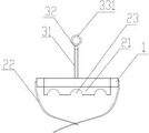
图1是本实用新型的主试结构示意图; Fig. 1 is the main test structural representation of the utility model;
图2是本实用新型的左视结构示意图; Fig. 2 is a left view structural representation of the utility model;
图3是本实用新型的俯视结构示意图; Fig. 3 is the top view structural representation of the utility model;
图4是本实用新型的仰视结构示意图; Fig. 4 is the structural representation of looking up of the utility model;
其中:1、主框架 11、纵梁 12、横梁 2、接地棒固定装置 21、接地棒固定块 22、绑带 23、半圆形凹槽 3、绕线架 31、绕线杆 32、阻挡杆 33、接地针固定装置。
Among them: 1. Main frame 11. Longitudinal beam 12. Cross beam 2. Grounding
具体实施方式 Detailed ways
如图1-2所示,一种新型接地线架,包括主框架1、接地棒固定装置2和绕线架3。所述主框架1包括两条纵梁11和三条横梁12,三条横梁12水平固定在两条纵梁11之间。所述绕线架3固定在主框架1横梁12的前侧,所述接地棒固定装置2包括接地棒固定块21和能够将接地棒绑紧的绑带22,所述接地棒固定块21上设有若干个与接地棒相适配的半圆形凹槽23,接地棒固定块21固定在主体框架1横梁12的后侧,所述绑带22固定在接地棒固定块21的两侧。
As shown in Figure 1-2, a new type of ground wire frame includes a main frame 1, a ground rod fixing device 2 and a wire winding frame 3. The main frame 1 includes two longitudinal beams 11 and three cross beams 12 , and the three cross beams 12 are horizontally fixed between the two longitudinal beams 11 . The winding frame 3 is fixed on the front side of the crossbeam 12 of the main frame 1, and the grounding rod fixing device 2 includes a grounding
如图2所示,所述绕线架3包括两个绕线杆31、阻挡杆32和接地针固定装置33。一个绕线杆31固定在一条横梁12上,另一个绕线杆31固定在另一条横梁12上。阻挡杆32与两条绕线杆31固定连接,阻挡杆32的长度大于两个绕线杆31间的距离,阻挡杆、绕线杆和纵梁之间形成绕线槽。所述接地针固定装置33固定在所述阻挡杆32上,绕线杆31和接地针固定装置33位于阻挡杆32的两侧。如图3-4所示,所述接地针固定装置33包括接地针固定环331和接地针固定钩332,所述接地针固定环331固定在阻挡杆32的一端,所述接地针固定钩332固定在阻挡杆32的另一端。接地针一端可以放置在接地针固定环内,另一端可以放置在接地针固定钩内,接地针固定钩为不封闭的圆环形,方便取出或放入接地针,使用方便。
As shown in FIG. 2 , the winding frame 3 includes two
在使用所述接地线架时,首先将接地棒的一端挂在接地线架最上端的横梁上,另一端放置在接地棒固定块的凹槽内,并使用绑带将其固定牢固;然后,将接地线整齐的缠绕在绕线架上;最后,将接地针固定在接地针固定装置上。使用所述接地线架,能够可靠的固定接地线、接地棒和接地针,保证在接地线不使用时整齐,不易损坏,且携带方便。 When using the grounding wire frame, first hang one end of the grounding rod on the uppermost beam of the grounding wire frame, place the other end in the groove of the grounding rod fixing block, and fix it firmly with a strap; then, place the The grounding wire is neatly wound on the winding frame; finally, the grounding pin is fixed on the grounding pin fixture. The grounding wire frame can reliably fix the grounding wire, the grounding rod and the grounding needle, and ensure that the grounding wire is neat, not easy to be damaged, and easy to carry when the grounding wire is not in use.
本文中应用了具体个例对本实用新型的原理及其实施方式进行了阐述,以上实施例的说明只是用来帮助理解本实用新型的方法及其核心思想。应当指出,对于本领域的普通技术人员来说,在不脱离本实用新型原理的前提下还可以对本实用新型进行若干改进和修饰,这些改进和修饰也落入本实用新型权利要求的保护范围内。 In this paper, specific examples are used to illustrate the principle of the utility model and its implementation. The description of the above embodiments is only used to help understand the method of the utility model and its core idea. It should be pointed out that for those of ordinary skill in the art, some improvements and modifications can also be made to the utility model without departing from the principle of the utility model, and these improvements and modifications also fall within the protection scope of the claims of the utility model .
Claims (3)
Priority Applications (1)
| Application Number | Priority Date | Filing Date | Title |
|---|---|---|---|
| CN201320601592.3U CN203497856U (en) | 2013-09-28 | 2013-09-28 | Novel grounding wire frame |
Applications Claiming Priority (1)
| Application Number | Priority Date | Filing Date | Title |
|---|---|---|---|
| CN201320601592.3U CN203497856U (en) | 2013-09-28 | 2013-09-28 | Novel grounding wire frame |
Publications (1)
| Publication Number | Publication Date |
|---|---|
| CN203497856U true CN203497856U (en) | 2014-03-26 |
Family
ID=50328854
Family Applications (1)
| Application Number | Title | Priority Date | Filing Date |
|---|---|---|---|
| CN201320601592.3U Expired - Fee Related CN203497856U (en) | 2013-09-28 | 2013-09-28 | Novel grounding wire frame |
Country Status (1)
| Country | Link |
|---|---|
| CN (1) | CN203497856U (en) |
Cited By (5)
| Publication number | Priority date | Publication date | Assignee | Title |
|---|---|---|---|---|
| CN105110095A (en) * | 2015-08-18 | 2015-12-02 | 辽宁省电力有限公司丹东供电公司 | Ground wire winding frame |
| CN105565086A (en) * | 2016-01-22 | 2016-05-11 | 国家电网公司 | Disc-type take-up and pay-off device for ground wire |
| CN105565080A (en) * | 2016-01-22 | 2016-05-11 | 国家电网公司 | Support type 10kV ground wire rotary winding device |
| CN106144778A (en) * | 2016-07-13 | 2016-11-23 | 国网福建省电力有限公司 | A kind of portable earth lead accepting rack |
| CN107444980A (en) * | 2017-08-16 | 2017-12-08 | 陈爱军 | A kind of high-voltage earthing rod storage device |
-
2013
- 2013-09-28 CN CN201320601592.3U patent/CN203497856U/en not_active Expired - Fee Related
Cited By (5)
| Publication number | Priority date | Publication date | Assignee | Title |
|---|---|---|---|---|
| CN105110095A (en) * | 2015-08-18 | 2015-12-02 | 辽宁省电力有限公司丹东供电公司 | Ground wire winding frame |
| CN105565086A (en) * | 2016-01-22 | 2016-05-11 | 国家电网公司 | Disc-type take-up and pay-off device for ground wire |
| CN105565080A (en) * | 2016-01-22 | 2016-05-11 | 国家电网公司 | Support type 10kV ground wire rotary winding device |
| CN106144778A (en) * | 2016-07-13 | 2016-11-23 | 国网福建省电力有限公司 | A kind of portable earth lead accepting rack |
| CN107444980A (en) * | 2017-08-16 | 2017-12-08 | 陈爱军 | A kind of high-voltage earthing rod storage device |
Similar Documents
| Publication | Publication Date | Title |
|---|---|---|
| CN105668348A (en) | Safe electricity ground wire stand convenient to use | |
| CN207069523U (en) | Insulating sheath component for aerial condutor sectioning | |
| CN203250964U (en) | Mobile grounding device | |
| CN204407846U (en) | A kind of line lightning arrestor | |
| CN204400356U (en) | A kind of pole tower ground resistance testing wire draw off gear | |
| CN203826054U (en) | Anti-compression flat copper cable | |
| CN203688861U (en) | Remaining cable support with adjustable fixed pin | |
| CN205212395U (en) | Lightning protection protector is synthesized in drainage of strain insulator pole | |
| CN205713388U (en) | A kind of electric pole of band lightning function | |
| CN203967688U (en) | The anti-disconnected device of center cracking resistance of long-distance transmission line | |
| CN203553726U (en) | A protector for a stay wire of an electric pole | |
| CN210985456U (en) | Ground wire suspension bracket for line pole | |
| CN201994147U (en) | Wire insulating protective cover for live-wire work | |
| CN205724376U (en) | A kind of lightning rod | |
| CN205318886U (en) | Magnetic suspension three -core flat cable | |
| CN107082325A (en) | 10 kilovolts of semi-automatic winds of distribution Special grounding wire | |
| CN203732767U (en) | Residual cable fixing bracket | |
| CN202967741U (en) | Grounding frame | |
| CN204376210U (en) | Controller switching equipment | |
| CN102737819A (en) | Transformer | |
| CN204241732U (en) | An optical cable transfer box with a grounding device | |
| CN205141179U (en) | Articulate ground wire | |
| CN104466699A (en) | Power distribution equipment | |
| CN203826095U (en) | Cable | |
| CN204905658U (en) | Fixed lightning rod of side direction |
Legal Events
| Date | Code | Title | Description |
|---|---|---|---|
| GR01 | Patent grant | ||
| GR01 | Patent grant | ||
| CF01 | Termination of patent right due to non-payment of annual fee | ||
| CF01 | Termination of patent right due to non-payment of annual fee |
Granted publication date: 20140326 Termination date: 20180928 |