CN203493412U - Vacuum electric heating container - Google Patents
Vacuum electric heating container Download PDFInfo
- Publication number
- CN203493412U CN203493412U CN201320530375.XU CN201320530375U CN203493412U CN 203493412 U CN203493412 U CN 203493412U CN 201320530375 U CN201320530375 U CN 201320530375U CN 203493412 U CN203493412 U CN 203493412U
- Authority
- CN
- China
- Prior art keywords
- pot
- assembly
- vacuum
- electric heating
- buckle
- Prior art date
- Legal status (The legal status is an assumption and is not a legal conclusion. Google has not performed a legal analysis and makes no representation as to the accuracy of the status listed.)
- Expired - Lifetime
Links
Images


Landscapes
- Cookers (AREA)
Abstract
本实用新型公开了一种真空电热容器,包括:真空壶身组件,真空壶身组件具有壶口,真空壶身组件包括密封连接的外胆和设在外胆内的内胆;发热体组件,发热体组件设在真空壶身组件的底部;手柄组件,手柄组件设在外胆外且其上端连接至壶口处,手柄组件内形成有与壶口连通的通水开口;以及壶盖组件,壶盖组件连接在手柄组件的顶部且对应于通水开口的上端。根据本实用新型的真空电热容器,壶盖组件与真空壶身组件装配牢固,使真空电热容器具有良好的保温效果。而且,壶盖组件与真空壶身组件装配后容易拆卸,使用起来更加方便。
The utility model discloses a vacuum electric heating container, which comprises: a vacuum pot body assembly, the vacuum pot body assembly has a spout, and the vacuum pot body assembly includes an outer container which is sealed and connected and an inner container arranged in the outer container; The body assembly is arranged at the bottom of the vacuum pot body assembly; the handle assembly is arranged outside the outer bladder and its upper end is connected to the spout, and a water opening connected with the spout is formed in the handle assembly; and the lid assembly, the lid The assembly is connected to the top of the handle assembly and corresponds to the upper end of the water opening. According to the vacuum electric heating container of the utility model, the pot lid assembly and the vacuum pot body assembly are firmly assembled, so that the vacuum electric heating container has a good heat preservation effect. Moreover, the pot lid component and the vacuum pot body component can be easily disassembled after being assembled, making it more convenient to use.
Description
技术领域technical field
本实用新型涉及家用电器技术领域,具体而言,涉及一种真空电热容器。The utility model relates to the technical field of household appliances, in particular to a vacuum electric heating container.
背景技术Background technique
真空电热容器的壶盖组件与真空壶身组件连接,在连接处需要隔热保温,但现有的壶盖组件和真空壶身组件无法做到,使真空壶身组件被稳定的固定的同时,又使壶盖组件便于从真空壶身组件上拆卸。The lid assembly of the vacuum electric heating container is connected to the vacuum body assembly, and heat insulation is required at the joint, but the existing lid assembly and vacuum body assembly cannot do this, so that the vacuum body assembly is stably fixed, It also makes the pot lid assembly easy to disassemble from the vacuum pot body assembly.
实用新型内容Utility model content
本实用新型旨在至少解决现有技术中存在的技术问题之一。为此,本实用新型的一个目的在于提出一种壶盖组件与真空壶身组件装配牢固,且容易拆卸的具有良好的保温效果的真空电热容器。The utility model aims at at least solving one of the technical problems existing in the prior art. Therefore, an object of the present utility model is to provide a vacuum electric heating container with a good thermal insulation effect, which is firmly assembled with the lid assembly and the vacuum body assembly, and is easy to disassemble.
根据本实用新型的真空电热容器,包括:真空壶身组件,所述真空壶身组件具有壶口,所述真空壶身组件包括外胆和设在所述外胆内的内胆;发热体组件,所述发热体组件设在真空壶身组件的底部;手柄组件,所述手柄组件设在所述外胆外且其上端连接至所述壶口处,所述手柄组件内形成有与所述壶口连通的通水开口;以及壶盖组件,所述壶盖组件连接在所述手柄组件的顶部且对应于所述通水开口的上端。The vacuum electric heating container according to the utility model includes: a vacuum pot body assembly, the vacuum pot body assembly has a spout, and the vacuum pot body assembly includes an outer container and an inner container arranged in the outer container; a heating body assembly , the heating element assembly is arranged at the bottom of the vacuum pot body assembly; the handle assembly is arranged outside the outer bladder and its upper end is connected to the spout, and the handle assembly is formed with the a water opening connected to the mouth of the pot; and a pot cover assembly connected to the top of the handle assembly and corresponding to the upper end of the water opening.
根据本实用新型的实施例的真空电热容器,壶盖组件与真空壶身组件装配牢固,使真空电热容器具有良好的保温效果。而且,壶盖组件与真空壶身组件装配后容易拆卸,使用起来更加方便。According to the vacuum electric heating container of the embodiment of the utility model, the pot lid assembly and the vacuum pot body assembly are firmly assembled, so that the vacuum electric heating container has a good heat preservation effect. Moreover, the pot lid assembly and the vacuum pot body assembly are easy to disassemble after being assembled, making it more convenient to use.
另外,根据本实用新型的真空电热容器还具有如下附加技术特征:In addition, the vacuum electric heating capacitor according to the utility model also has the following additional technical features:
所述壶盖组件包括:壶盖主体,所述壶盖主体的底部具有壶盖主体孔,所述壶盖主体内部具有连通所述壶盖主体孔和外部的出水通道,所述壶盖主体的下部通过连接部与所述手柄组件连接;壶上盖,所述壶上盖连接在所述壶盖主体的上方且与所述壶盖主体之间限定出操作腔;以及出水阀,所述出水阀可轴向移动地设在所述操作腔内且下端穿过所述出水通道与所述壶盖主体孔对应以打开和关闭所述壶盖主体孔,所述出水阀上设有进气孔。The pot cover assembly includes: a pot cover main body, the bottom of the pot cover main body has a pot cover main body hole, the inside of the pot cover main body has a water outlet channel connecting the pot cover main body hole and the outside, the pot cover main body The lower part is connected with the handle assembly through the connecting part; the upper cover of the pot is connected above the main body of the pot cover and defines an operation cavity with the main body of the pot cover; and the water outlet valve, the water outlet The valve is axially movably arranged in the operating chamber and the lower end passes through the water outlet channel and corresponds to the main body hole of the pot cover to open and close the main body hole of the pot cover, and the water outlet valve is provided with an air inlet .
所述手柄组件包括:壶脖件;连接件,所述连接件设在所述壶脖件的底部,且所述壶脖件通过所述连接件设在所述真空壶身组件的顶部壶口处,其中所述通水开口沿轴向方向贯穿所述壶脖件和连接件;以及手柄,所述手柄的一端连接至所述壶脖件的外壁;其中所述壶盖主体的下部通过连接部与所述连接件相连。The handle assembly includes: a kettle neck; a connecting piece, the connecting piece is arranged at the bottom of the kettle neck, and the kettle neck is arranged on the top spout of the vacuum kettle body assembly through the connecting piece , wherein the water opening runs through the neck piece and the connecting piece in the axial direction; and a handle, one end of which is connected to the outer wall of the neck piece; wherein the lower part of the lid body is connected connected to the connector.
所述连接部为设在所述壶盖主体外周壁上的、沿径向向外延伸出的第一扣位,所述通水开口的内周壁上具有沿径向向内延伸出的第二扣位,所述第二扣位与所述第一扣位对应装配。The connecting portion is a first buckle extending radially outwards provided on the outer peripheral wall of the main body of the pot lid, and a second button extending radially inwards is provided on the inner peripheral wall of the water opening. buckle, the second buckle is assembled correspondingly to the first buckle.
所述壶脖件和所述连接件之间具有沿所述通水开口的径向向内延伸的止挡件;所述连接部包括:按压件,所述按压件设在所述操作腔内且上端伸出所述壶上盖以便于被按压;以及卡扣件,所述卡扣件设在所述操作腔内且下端伸出所述壶盖主体以与所述止挡件配合,所述卡扣件的上端与所述按压件的下端配合且被构造成所述按压件被按下时所述卡扣件的下端脱离所述止挡件。There is a stopper extending inwardly along the radial direction of the water opening between the kettle neck and the connecting member; the connecting part includes: a pressing member, which is arranged in the operating chamber And the upper end protrudes from the pot upper cover so as to be pressed; and the buckle, the buckle is arranged in the operation cavity and the lower end protrudes from the main body of the pot cover to cooperate with the stopper, so The upper end of the buckle is matched with the lower end of the pressing piece and is configured so that when the pressing piece is pressed, the lower end of the buckle is separated from the stopper.
所述卡扣件的上端形成有向内向上倾斜的倾斜部,所述按压件的下端形成有向外向上倾斜延伸出的翻边部,所述翻边部与所述倾斜部可移动地配合。The upper end of the buckle is formed with an inwardly upward inclined portion, and the lower end of the pressing member is formed with an outwardly upwardly inclined flanging portion, and the flanging portion is movably matched with the inclined portion .
所述操作腔内还具有支撑部,所述支撑部套设在所述出水阀外,所述卡扣件通过第一弹簧套设在所述支撑部外。There is also a supporting part inside the operating chamber, the supporting part is sleeved on the outside of the water outlet valve, and the buckle is sleeved on the outside of the supporting part through the first spring.
所述连接部为设在所述壶盖主体外周壁上的外螺纹,所述手柄组件的所述连接件的内周壁上具有与所述外螺纹配合的内螺纹。The connecting part is an external thread provided on the outer peripheral wall of the main body of the pot lid, and the inner peripheral wall of the connecting part of the handle assembly has an internal thread mated with the external thread.
所述出水阀包括:阀体,所述阀体通过第二弹簧可轴向移动地设在所述操作腔内且下端穿过所述出水通道;以及阀板,所述阀板设在所述阀体的下端,且所述进气孔设在阀板上。The water outlet valve includes: a valve body, the valve body is axially movably arranged in the operation chamber through a second spring, and the lower end of the valve body passes through the water outlet channel; and a valve plate, the valve plate is arranged on the The lower end of the valve body, and the air inlet hole is arranged on the valve plate.
所述壶盖组件进一步包括:按制开关,所述按制开关可枢转地连接在所述操作腔内且另一端伸出所述壶上盖外,所述按制开关被构造成给所述出水阀的上端外力以使所述出水阀轴向移动。The lid assembly further includes: a press switch, the press switch is pivotally connected in the operation chamber and the other end protrudes from the upper cover of the pot, and the press switch is configured to give the The external force on the upper end of the water outlet valve makes the water outlet valve move axially.
所述内胆包括:第一内胆,所述第一内胆与所述外胆的上端密封连接;第二内胆,所述第二内胆设在所述第一内胆的底部;第三内胆,所述第三内胆设在所述第二内胆的底部且与所述第二内胆限定出容纳空间,其中所述发热体组件设在所述容纳空间内。The inner tank includes: a first inner tank, which is sealed and connected with the upper end of the outer tank; a second inner tank, which is arranged at the bottom of the first inner tank; Three inner tanks, the third inner tank is arranged at the bottom of the second inner tank and defines an accommodating space with the second inner tank, wherein the heating element assembly is arranged in the accommodating space.
所述外胆包括:第一外胆,所述第一外胆的上端与所述第一内胆的上端密封连接;第二外胆,所述第二外胆设在所述第一外胆的底部,所述第二外胆和所述第三内胆在所述开口处密封连接。The outer bladder includes: a first outer bladder, the upper end of the first outer bladder is sealed and connected with the upper end of the first inner bladder; a second outer bladder, the second outer bladder is arranged on the first outer bladder The bottom of the second outer bladder and the third inner bladder are sealingly connected at the opening.
本实用新型的附加方面和优点将在下面的描述中部分给出,部分将从下面的描述中变得明显,或通过本实用新型的实践了解到。Additional aspects and advantages of the invention will be set forth in the description which follows, and in part will be obvious from the description, or may be learned by practice of the invention.
附图说明Description of drawings
本实用新型的上述和/或附加的方面和优点从结合下面附图对实施例的描述中将变得明显和容易理解,其中:The above and/or additional aspects and advantages of the present utility model will become apparent and easy to understand from the description of the embodiments in conjunction with the following drawings, wherein:
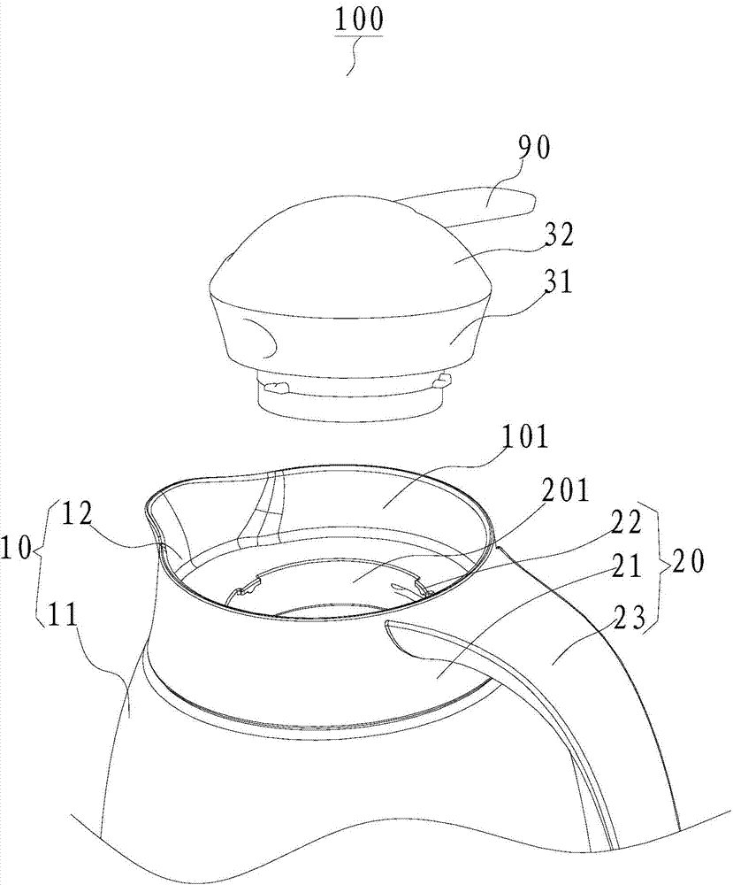
图1是根据本实用新型的一个实施例的真空电热容器的立体分解示意图;Fig. 1 is a three-dimensional exploded schematic view of a vacuum electric heating capacitor according to an embodiment of the present invention;
图2是根据本实用新型的一个实施例的真空电热容器的剖视图;Fig. 2 is a cross-sectional view of a vacuum electric heating container according to an embodiment of the present invention;
图3是根据本实用新型的另一个实施例的真空电热容器的壶盖组件的立体结构示意图;Fig. 3 is a three-dimensional structural schematic diagram of a pot lid assembly of a vacuum electric heating container according to another embodiment of the present invention;
图4是根据本实用新型的另一个实施例的真空电热容器的滑盖组件与真空壶身组件装配后的剖视图;Fig. 4 is a cross-sectional view after the assembly of the sliding cover assembly and the vacuum pot body assembly of the vacuum electric heating container according to another embodiment of the present invention;
图5是根据本实用新型的再一个实施例的真空电热容器的立体分解示意图;Fig. 5 is a three-dimensional exploded schematic diagram of a vacuum electric heating capacitor according to yet another embodiment of the present invention;
图6是根据本实用新型的再一个实施例的真空电热容器的剖视图;Fig. 6 is a cross-sectional view of a vacuum electric heating capacitor according to yet another embodiment of the present invention;
图7是根据本实用新型的一个实施例的真空电热容器的结构示意图。Fig. 7 is a schematic structural view of a vacuum electric heating capacitor according to an embodiment of the present invention.
附图标记说明:Explanation of reference signs:
真空电热容器100;壶口101;通水开口201;Vacuum
真空壶身组件10;外胆11;内胆12;Vacuum
手柄组件20;壶脖件21;连接件22;手柄23;
壶盖组件30;壶盖主体31;壶上盖32;出水阀33;出水通道34;The
壶盖主体孔311;进气孔331;阀板332;阀体333;Pot cover body hole 311; air intake hole 331; valve plate 332; valve body 333;
连接部40;按压件41;卡扣件42;Connecting part 40;
翻边部411;倾斜部421;Flange
操作腔50;
止挡件60;
支撑部70;
第一弹簧81;第二弹簧82;The
按制开关90;Press the
第一内胆131;第二内胆132;133第三内胆;第一外胆141;第二外胆142;发热体组件99。The first
具体实施方式Detailed ways
下面详细描述本实用新型的实施例,所述实施例的示例在附图中示出,其中自始至终相同或类似的标号表示相同或类似的元件或具有相同或类似功能的元件。下面通过参考附图描述的实施例是示例性的,仅用于解释本实用新型,而不能理解为对本实用新型的限制。Embodiments of the present invention are described in detail below, examples of which are shown in the drawings, wherein the same or similar reference numerals represent the same or similar elements or elements having the same or similar functions throughout. The embodiments described below with reference to the accompanying drawings are exemplary and are only used to explain the present utility model, but should not be construed as limiting the present utility model.
在本实用新型的描述中,需要理解的是,术语“中心”、“纵向”、“横向”、“上”、“下”、“前”、“后”、“左”、“右”、“竖直”、“水平”、“顶”、“底”、“内”、“外”等指示的方位或位置关系为基于附图所示的方位或位置关系,仅是为了便于描述本实用新型和简化描述,而不是指示或暗示所指的装置或元件必须具有特定的方位、以特定的方位构造和操作,因此不能理解为对本实用新型的限制。此外,术语“第一”、“第二”仅用于描述目的,而不能理解为指示或暗示相对重要性或者隐含指明所指示的技术特征的数量。由此,限定有“第一”、“第二”的特征可以明示或者隐含地包括一个或者更多个该特征。在本实用新型的描述中,除非另有说明,“多个”的含义是两个或两个以上。In describing the present utility model, it should be understood that the terms "center", "longitudinal", "transverse", "upper", "lower", "front", "rear", "left", "right", The orientations or positional relationships indicated by "vertical", "horizontal", "top", "bottom", "inner", "outer", etc. are based on the orientation or positional relationships shown in the drawings, and are only for the convenience of describing the present invention. Novel and simplified descriptions do not indicate or imply that the device or element referred to must have a specific orientation, be constructed and operate in a specific orientation, and therefore should not be construed as limiting the utility model. In addition, the terms "first" and "second" are used for descriptive purposes only, and cannot be interpreted as indicating or implying relative importance or implicitly specifying the quantity of indicated technical features. Thus, a feature defined as "first" and "second" may explicitly or implicitly include one or more of these features. In the description of the present utility model, unless otherwise specified, "plurality" means two or more.
在本实用新型的描述中,需要说明的是,除非另有明确的规定和限定,术语“安装”、“相连”、“连接”应做广义理解,例如,可以是固定连接,也可以是可拆卸连接,或一体地连接;可以是机械连接,也可以是电连接;可以是直接相连,也可以通过中间媒介间接相连,可以是两个元件内部的连通。对于本领域的普通技术人员而言,可以具体情况理解上述术语在本实用新型中的具体含义。In the description of the present utility model, it should be noted that, unless otherwise clearly stipulated and limited, the terms "installation", "connection" and "connection" should be understood in a broad sense, for example, it can be a fixed connection or a flexible connection. Detachable connection, or integral connection; it can be mechanical connection or electrical connection; it can be direct connection or indirect connection through an intermediary, and it can be the internal communication of two components. Those of ordinary skill in the art can understand the specific meanings of the above terms in the present utility model in specific situations.
如图1、图7所示,根据本实用新型的实施例的真空电热容器100,包括:真空壶身组件10、手柄组件20以及壶盖组件30。As shown in FIG. 1 and FIG. 7 , the vacuum
具体而言,真空壶身组件10可以具有壶口101,壶口101可以用于向真空电热容器100内注水,或通过壶口101向外倒水。真空壶身组件10可以包括外胆11和设在外胆11内的内胆12,以在外胆11和内胆12之间形成有真空腔,以起到保温的作用。发热体组件99可以设在真空壶身组件10的底部,以对真空壶身组件内的液体进行加热。手柄组件20可以设在外胆11外且其上端连接至壶口101处,以将手柄组件20与真空壶身组件固定连接。手柄组件20内可以形成有与壶口101连通的通水开口201,以方便水进入真空电热容器100内和由真空电热容器100内向外倒出。壶盖组件30可以连接在手柄组件20的顶部且对应于通水开口201的上端,以对通水开口201和壶口101密封。Specifically, the
根据本实用新型的实施例的真空电热容器100,壶盖组件30与真空壶身组件10装配牢固,使真空电热容器100具有良好的保温效果。而且,壶盖组件30与真空壶身组件10装配后容易拆卸,使用起来更加方便。According to the vacuum
如图2所示,根据本实用新型的一个实施例,壶盖组件30可以包括:壶盖主体31、壶上盖32以及出水阀33。As shown in FIG. 2 , according to an embodiment of the present invention, the
具体地,壶盖主体31的底部具有壶盖主体孔311,壶盖主体31内部具有连通壶盖主体孔311和外部的出水通道34,壶盖主体31的下部通过连接部40与手柄组件20连接。壶上盖32可以连接在壶盖主体31的上方且与壶盖主体31之间限定出操作腔50。出水阀33可轴向移动地设在操作腔50内且下端穿过出水通道34与壶盖主体孔311对应以打开和关闭壶盖主体孔311,出水阀33上设有进气孔331,以与大气相通。Specifically, the bottom of the
如图2所示,根据本实用新型的一个实施例,手柄组件20可以包括:壶脖件21、连接件22以及手柄23。As shown in FIG. 2 , according to an embodiment of the present invention, the
具体而言,连接件22设在壶脖件21的底部,且壶脖件21通过连接件22设在真空壶身组件10的顶部壶口101处,即,壶脖件21通过连接件22与真空壶身组件10的顶部的壶口101连接,其中通水开口201沿轴向方向贯穿壶脖件21和连接件22,以将通水开口201与内胆12的内部连通。手柄23的一端连接至壶脖件21的外壁。其中壶盖主体31的下部通过连接部22与连接件22相连。由此,手柄组件20可以与真空壶身组件10实现牢固的连接,且方便使用者通过手柄23移动真空电加热容器100。并且,可以将壶盖主体31定位在真空电加热容器100上。Specifically, the connecting
如图1、图2所示,根据本实用新型的一个实施例,连接部40为设在壶盖主体31外周壁上的、沿径向向外延伸出的第一扣位,通水开口201的内周壁上具有沿径向向内延伸出的第二扣位,第二扣位与第一扣位对应装配。由此,通过第一扣位和第二扣位的配合,可以将壶盖主体31定位在真空壶身组件10之上。As shown in Figures 1 and 2, according to an embodiment of the present invention, the connecting portion 40 is a first buckle located on the outer peripheral wall of the
如图3、图4所示,根据本实用新型的一个实施例,壶脖件21和连接件22之间具有沿通水开口201的径向向内延伸的止挡件60。连接部40可以包括:按压件41以及卡扣件42,按压件41设在操作腔50内且上端伸出壶上盖32以便于被按压。卡扣件42设在操作腔50内且下端伸出壶盖主体31以与止挡件60配合,卡扣件42的上端与按压件41的下端配合且被构造成按压件41被按下时卡扣件42的下端脱离止挡件60。由此,可以实现通过控制按压件41控制卡扣件42与止挡件60的卡合和分离,以实现真空壶身组件10与壶盖组件30的卡合和分离。As shown in FIG. 3 and FIG. 4 , according to an embodiment of the present invention, there is a
如图4所示,根据本实用新型的一个实施例,卡扣件42的上端形成有向内向上倾斜的倾斜部421,按压件41的下端形成有向外向上倾斜延伸出的翻边部411,翻边部411与倾斜部421可移动地配合。由此,可以通过翻边部411与倾斜部421的相互作用实现真空壶身组件10与壶盖组件30的卡合和分离。As shown in FIG. 4 , according to an embodiment of the present invention, the upper end of the
如图4所示,根据本实用新型的一个实施例,操作腔50内还具有支撑部70,支撑部70套设在出水阀33外,卡扣件42通过第一弹簧81套设在支撑部70外。由此,第一弹簧81可以为卡扣件42提供弹力,以在不对卡扣件42施加外力的情况下,使卡扣件42与止挡件60保持卡合。As shown in FIG. 4 , according to an embodiment of the present invention, the operating
如图5、图6所示,根据本实用新型的一个实施例,连接部40可以为设在壶盖主体31外周壁上的外螺纹,手柄组件20的连接件22的内周壁上具有与外螺纹配合的内螺纹。由此,可以通过外螺纹和内螺纹之间的配合将壶盖组件30与手柄组件连接。As shown in Fig. 5 and Fig. 6, according to an embodiment of the present invention, the connecting part 40 may be an external thread provided on the outer peripheral wall of the
如图2所示,根据本实用新型的一个实施例,出水阀33可以包括:阀体333以及阀板332。阀体333通过第二弹簧82可轴向移动地设在操作腔50内且下端穿过出水通道201。阀板332设在阀体333的下端,且进气孔331设在阀板332上。进一步地,根据本实用新型的一个实施例,壶盖组件30进一步包括:按制开关90,按制开关90可枢转地连接在操作腔50内且另一端伸出壶上盖32外,按制开关90被构造成给出水阀33的上端外力以使出水阀33轴向移动。由此,以在出水阀33的阀板332处于低位时封闭真空壶身组件10的壶口101,出水阀33的阀板332处于高位时打开真空壶身组件10的壶口101。As shown in FIG. 2 , according to an embodiment of the present invention, the
如图7所示,内胆可以包括:第一内胆131、第二内胆132和第三内胆133,第一内胆131与外胆的顶部密封连接。第二内胆132设在第一内胆131的底部。第三内胆133设在所述第二内胆132的底部且与第二内胆132限定出容纳空间,其中发热体组件设在容纳空间内。As shown in FIG. 7 , the inner container may include: a first
例如在图7的示例中,第一内胆131的顶部和底部均敞开,第一内胆131的顶部与外胆的顶部密封连接,第二内胆132连接在第一内胆131的底部且与第一内胆131共同限定出盛放液体的盛放空间,第三内胆133的顶部敞开,第三内胆133的顶部连接在第二内胆132的底部,且第三内胆133的底壁与第二内胆132的底壁在竖直方向上彼此间隔开,以共同限定出容纳空间,发热体组件设在容纳空间内以对盛放空间内的液体进行加热。由此,通过设置第三内胆133,有效地保证了真空电热容器100的保温效果。For example in the example of Fig. 7, the top and the bottom of the
进一步地,如图7所示,外胆包括:第一外胆141和第二外胆142,第一外胆141的顶部与第一内胆131的顶部密封连接。第二外胆142设在第一外胆141的底部,第二外胆142和第三内胆133在开口12处密封连接。Further, as shown in FIG. 7 , the outer bladder includes: a first
例如在图7的示例中,第一外胆141的顶部和底部均敞开,第一外胆141的顶部与第一内胆131的顶部密封连接,第二外胆142连接在第一外胆141的底部,第二外胆142和第三内胆133在开口12处密封连接,这样有效地保证了真空电热容器100的保温效果。For example in the example of Fig. 7, the top and the bottom of the first
在本说明书的描述中,参考术语“一个实施例”、“一些实施例”、“示意性实施例”、“示例”、“具体示例”、或“一些示例”等的描述意指结合该实施例或示例描述的具体特征、结构、材料或者特点包含于本实用新型的至少一个实施例或示例中。在本说明书中,对上述术语的示意性表述不一定指的是相同的实施例或示例。而且,描述的具体特征、结构、材料或者特点可以在任何的一个或多个实施例或示例中以合适的方式结合。In the description of this specification, references to the terms "one embodiment," "some embodiments," "exemplary embodiments," "example," "specific examples," or "some examples" are intended to mean that the implementation Specific features, structures, materials or characteristics described in an embodiment or example are included in at least one embodiment or example of the present invention. In this specification, schematic representations of the above terms do not necessarily refer to the same embodiment or example. Furthermore, the specific features, structures, materials or characteristics described may be combined in any suitable manner in any one or more embodiments or examples.
尽管已经示出和描述了本实用新型的实施例,本领域的普通技术人员可以理解:在不脱离本实用新型的原理和宗旨的情况下可以对这些实施例进行多种变化、修改、替换和变型,本实用新型的范围由权利要求及其等同物限定。Although the embodiments of the present invention have been shown and described, those skilled in the art can understand that various changes, modifications, substitutions and modifications, the scope of the present invention is defined by the claims and their equivalents.
Claims (12)
Priority Applications (1)
| Application Number | Priority Date | Filing Date | Title |
|---|---|---|---|
| CN201320530375.XU CN203493412U (en) | 2013-08-28 | 2013-08-28 | Vacuum electric heating container |
Applications Claiming Priority (1)
| Application Number | Priority Date | Filing Date | Title |
|---|---|---|---|
| CN201320530375.XU CN203493412U (en) | 2013-08-28 | 2013-08-28 | Vacuum electric heating container |
Publications (1)
| Publication Number | Publication Date |
|---|---|
| CN203493412U true CN203493412U (en) | 2014-03-26 |
Family
ID=50324429
Family Applications (1)
| Application Number | Title | Priority Date | Filing Date |
|---|---|---|---|
| CN201320530375.XU Expired - Lifetime CN203493412U (en) | 2013-08-28 | 2013-08-28 | Vacuum electric heating container |
Country Status (1)
| Country | Link |
|---|---|
| CN (1) | CN203493412U (en) |
Cited By (1)
| Publication number | Priority date | Publication date | Assignee | Title |
|---|---|---|---|---|
| CN107969938A (en) * | 2016-10-24 | 2018-05-01 | Seb公司 | Household cooking appliance including middle cover |
-
2013
- 2013-08-28 CN CN201320530375.XU patent/CN203493412U/en not_active Expired - Lifetime
Cited By (2)
| Publication number | Priority date | Publication date | Assignee | Title |
|---|---|---|---|---|
| CN107969938A (en) * | 2016-10-24 | 2018-05-01 | Seb公司 | Household cooking appliance including middle cover |
| CN107969938B (en) * | 2016-10-24 | 2023-07-28 | Seb公司 | Household cooking appliance comprising a middle cover |
Similar Documents
| Publication | Publication Date | Title |
|---|---|---|
| KR102376066B1 (en) | Vacuum sealed lead inserts for insulated containers | |
| CN104146615A (en) | Water gauge of hydrothermal pressure cooker | |
| CN203153404U (en) | Pressure-cooker cooker cover and electric pressure cooker with same | |
| CN103799813A (en) | Intelligent cup for rapidly drinking | |
| CN203447159U (en) | Pot lid assembly used for vacuum electric heating container and vacuum electric heating container | |
| CN203954219U (en) | Milk powder box and milk making device | |
| CN203447109U (en) | Vacuum electric heating container | |
| CN102106692A (en) | Electric kettle with double-layer structure | |
| CN203447099U (en) | Vacuum electric heating container | |
| CN203447102U (en) | Vacuum electric heating container | |
| CN205359230U (en) | drinking water equipment | |
| CN204950702U (en) | Oilcan of taking is got to ration | |
| CN204158204U (en) | Novel saucepan | |
| CN208625389U (en) | Pot lid, kettle and drinking equipment | |
| CN102715833A (en) | electric kettle | |
| CN110141121A (en) | Lids, jugs and drinking equipment | |
| MX2024014285A (en) | Opening adapter assembly for a container | |
| CN205285828U (en) | A cup that adjusts temperature for on thermos cup | |
| CN208371441U (en) | A double gallbladder | |
| CN209518677U (en) | Insulation cups and central sockets for thermos cups | |
| CN207444737U (en) | Stainless steel insertion slot type thermal insulation cup | |
| CN203341514U (en) | Pressure cooker | |
| CN204473460U (en) | A kind of emulsion pumps of energy rapid-assembling | |
| CN205379475U (en) | Swift formula feeding bottle | |
| CN204908926U (en) | Vacuum china spring cup |
Legal Events
| Date | Code | Title | Description |
|---|---|---|---|
| GR01 | Patent grant | ||
| GR01 | Patent grant | ||
| CX01 | Expiry of patent term |
Granted publication date: 20140326 |
|
| CX01 | Expiry of patent term |