CN203484021U - Boiler steam dust collector - Google Patents
Boiler steam dust collector Download PDFInfo
- Publication number
- CN203484021U CN203484021U CN201320595688.3U CN201320595688U CN203484021U CN 203484021 U CN203484021 U CN 203484021U CN 201320595688 U CN201320595688 U CN 201320595688U CN 203484021 U CN203484021 U CN 203484021U
- Authority
- CN
- China
- Prior art keywords
- steam
- dividing plate
- deduster
- dust collector
- disperses
- Prior art date
- Legal status (The legal status is an assumption and is not a legal conclusion. Google has not performed a legal analysis and makes no representation as to the accuracy of the status listed.)
- Expired - Fee Related
Links
- 239000000428 dust Substances 0.000 title abstract 10
- XLYOFNOQVPJJNP-UHFFFAOYSA-N water Substances O XLYOFNOQVPJJNP-UHFFFAOYSA-N 0.000 claims abstract description 33
- 239000010813 municipal solid waste Substances 0.000 claims description 4
- 230000000694 effects Effects 0.000 abstract 1
- 239000012535 impurity Substances 0.000 abstract 1
- 239000007789 gas Substances 0.000 description 3
- 239000003546 flue gas Substances 0.000 description 2
- UGFAIRIUMAVXCW-UHFFFAOYSA-N Carbon monoxide Chemical compound [O+]#[C-] UGFAIRIUMAVXCW-UHFFFAOYSA-N 0.000 description 1
- 238000002485 combustion reaction Methods 0.000 description 1
- 239000003500 flue dust Substances 0.000 description 1
- 239000004071 soot Substances 0.000 description 1
Images
Landscapes
- Separating Particles In Gases By Inertia (AREA)
Abstract
The utility model discloses a boiler steam dust collector. The boiler steam dust collector comprises a dust collector cylinder, one side of the bottom of the dust collector cylinder is provided with a steam inlet, the other end of the top of the dust collector cylinder is provided with an air outlet, a sump tank is arranged at the bottom in the dust collector cylinder, a water inlet is formed in one side of the top of the sump tank, a water outlet is formed in one side of the bottom of the sump tank, the steam inlet is formed in the bottom of the water inlet in one side of the sump tank, and an impurity removing chamber is arranged at the middle part in the dust collector cylinder. The boiler steam dust collector has the advantages that the overall structure is simple, the operation is convenient, the duration of stream in water is increased, the dust removal effect is more complete, and the work efficiency is improved.
Description
Technical field
The utility model relates to deduster, relates in particular to a kind of Boiler Steam deduster.
Background technology
Boiler oil except emitting amount of heat, also can produce a large amount of flue gases in combustion process.In order to reduce and to control the harm of boiler soot emission to environment, the steam that need produce boiler removes layer.In prior art, in Boiler Steam deduster, there is the water of take as medium, utilize the network of rivers, moisture film, water droplet trapping flue dust, flue gas is purified.Steam in entering water time the residence time in water too short, cause being purified completely.
Therefore, be badly in need of a kind of improved technology and solve existing this problem in prior art.
Utility model content
The utility model provides a kind of Boiler Steam deduster.
The technical solution adopted in the utility model is:
A kind of Boiler Steam deduster, comprise deduster cylindrical shell, described deduster cylinder body bottom one side is provided with steam inlet, the described deduster cylindrical shell top other end is provided with gas outlet, described deduster inner barrel bottom is provided with water leg, and described water leg top one side is provided with water inlet, and described water leg bottom one side is provided with delivery port, water leg one side water inlet bottom is located in described steam inlet, and described deduster inner barrel middle part is provided with trash chamber.
In described water leg, be provided with steam and disperse dividing plate.
Described steam disperses dividing plate to comprise that steam disperses dividing plate I and steam to disperse dividing plate II, described steam disperses dividing plate I to be located at steam and disperses dividing plate II upside, described steam disperses dividing plate I and has space in vain near steam inlet side inwall, and described steam disperses dividing plate II and has space in vain away from steam inlet side inwall.
The utility model has the advantages that: overall structure is simple, easy to operate, increase the time of steam in water, make dedusting more complete, increase work efficiency.
Accompanying drawing explanation
Below in conjunction with the drawings and specific embodiments, the utility model is described in further detail.
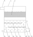
Fig. 1 is structural representation of the present utility model.
Wherein: 1, deduster cylindrical shell, 2, steam inlet, 3, gas outlet, 4, water leg, 5, water inlet, 6, delivery port, 7, trash chamber, 8, steam disperses dividing plate I, 9, steam disperses dividing plate II, 10, space.
The specific embodiment
As shown in Figure 1, a kind of Boiler Steam deduster of the present utility model, comprise deduster cylindrical shell 1, described deduster cylindrical shell 1 bottom one side is provided with steam inlet 2, the described deduster cylindrical shell 1 top other end is provided with gas outlet 3, described deduster cylindrical shell 1 interior bottom portion is provided with water leg 4, described water leg 4 top one sides are provided with water inlet 5, described water leg 4 bottom one sides are provided with delivery port 6, water leg 4 one side water inlet 5 bottoms are located in described steam inlet 2, the inner middle part of described deduster cylindrical shell 1 is provided with trash chamber 7, in described water leg 4, be provided with steam and disperse dividing plate, described steam disperses dividing plate to comprise that steam disperses dividing plate I 8 and steam to disperse dividing plate II 9, described steam disperses dividing plate I 8 to be located at steam and disperses dividing plate II 9 upsides, described steam disperses dividing plate I 8 and has space 10 in vain near steam inlet 2 side inwalls, described steam disperses dividing plate II 9 and has space 10 in vain away from steam inlet 2 side inwalls, overall structure is simple, easy to operate, increase the time of steam in water, make dedusting more complete, increase work efficiency.
Claims (3)
1. a Boiler Steam deduster, comprise deduster cylindrical shell, it is characterized in that: described deduster cylinder body bottom one side is provided with steam inlet, the described deduster cylindrical shell top other end is provided with gas outlet, described deduster inner barrel bottom is provided with water leg, and described water leg top one side is provided with water inlet, and described water leg bottom one side is provided with delivery port, water leg one side water inlet bottom is located in described steam inlet, and described deduster inner barrel middle part is provided with trash chamber.
2. a kind of Boiler Steam deduster according to claim 1, is characterized in that: in described water leg, be provided with steam and disperse dividing plate.
3. a kind of Boiler Steam deduster according to claim 2, it is characterized in that: described steam disperses dividing plate to comprise that steam disperses dividing plate I and steam to disperse dividing plate II, described steam disperses dividing plate I to be located at steam and disperses dividing plate II upside, described steam disperses dividing plate I and has space in vain near steam inlet side inwall, and described steam disperses dividing plate II and has space in vain away from steam inlet side inwall.
Priority Applications (1)
| Application Number | Priority Date | Filing Date | Title |
|---|---|---|---|
| CN201320595688.3U CN203484021U (en) | 2013-09-26 | 2013-09-26 | Boiler steam dust collector |
Applications Claiming Priority (1)
| Application Number | Priority Date | Filing Date | Title |
|---|---|---|---|
| CN201320595688.3U CN203484021U (en) | 2013-09-26 | 2013-09-26 | Boiler steam dust collector |
Publications (1)
| Publication Number | Publication Date |
|---|---|
| CN203484021U true CN203484021U (en) | 2014-03-19 |
Family
ID=50254883
Family Applications (1)
| Application Number | Title | Priority Date | Filing Date |
|---|---|---|---|
| CN201320595688.3U Expired - Fee Related CN203484021U (en) | 2013-09-26 | 2013-09-26 | Boiler steam dust collector |
Country Status (1)
| Country | Link |
|---|---|
| CN (1) | CN203484021U (en) |
-
2013
- 2013-09-26 CN CN201320595688.3U patent/CN203484021U/en not_active Expired - Fee Related
Similar Documents
| Publication | Publication Date | Title |
|---|---|---|
| CN207950949U (en) | A kind of energy-saving, environmental protection boiler emission-control equipment | |
| CN202199229U (en) | Tail gas deduster for conduction oil heating boiler | |
| CN106540500A (en) | A kind of boiler waste gas treating device | |
| CN204996283U (en) | Boiler exhaust -gas treatment apparatus | |
| CN108554060A (en) | Emission-control equipment is bleachinged and dyeing in a kind of weaving | |
| CN203582809U (en) | Condenser | |
| CN202328178U (en) | Energy-saving and emission-reducing combustion boiler device | |
| CN204716350U (en) | A kind of high efficiency filter sterilization cooling tube | |
| CN204637858U (en) | Shell and tube tail gas environment-friendly processing unit | |
| CN204337986U (en) | A kind of compact exhaust purifier | |
| CN203090691U (en) | Water bath dust collector for reducing emission of smoke and dust of boiler | |
| CN204716371U (en) | A kind of exhaust gases of internal combustion engines sterilization cooling tube | |
| CN204672056U (en) | A kind of purging exhaust steam recycle device | |
| CN203816411U (en) | Tail gas collecting system | |
| CN207576060U (en) | A kind of air filter | |
| CN204716369U (en) | A kind of internal-combustion engine sterilization heat radiation outlet pipe | |
| CN204227686U (en) | A kind of environment-protection boiler | |
| CN204933191U (en) | A kind of containing phenol waste gas, sulphur-containing exhaust gas centralized processor | |
| CN205717273U (en) | A kind of dust-settling compartment of biomass thermal wind furnace | |
| CN204299739U (en) | Motorcycle engine air intake filter | |
| CN204460257U (en) | A kind of boiler smoke udst separation residual heat using device | |
| CN203672198U (en) | Fuel gas indirect circulation cooler | |
| CN204543966U (en) | A kind of novel desulfurizer | |
| CN205445737U (en) | Internal combustion engine waste gas purifier | |
| CN205079581U (en) | Energy -saving appliance for oven |
Legal Events
| Date | Code | Title | Description |
|---|---|---|---|
| GR01 | Patent grant | ||
| GR01 | Patent grant | ||
| CF01 | Termination of patent right due to non-payment of annual fee |
Granted publication date: 20140319 Termination date: 20140926 |
|
| EXPY | Termination of patent right or utility model |