CN203481299U - Battery module combined structure suitable for quick-change battery box of pure electric bus - Google Patents
Battery module combined structure suitable for quick-change battery box of pure electric bus Download PDFInfo
- Publication number
- CN203481299U CN203481299U CN201320562830.4U CN201320562830U CN203481299U CN 203481299 U CN203481299 U CN 203481299U CN 201320562830 U CN201320562830 U CN 201320562830U CN 203481299 U CN203481299 U CN 203481299U
- Authority
- CN
- China
- Prior art keywords
- battery
- battery module
- quick change
- battery box
- insulation
- Prior art date
- Legal status (The legal status is an assumption and is not a legal conclusion. Google has not performed a legal analysis and makes no representation as to the accuracy of the status listed.)
- Expired - Fee Related
Links
- 239000012212 insulator Substances 0.000 claims abstract description 19
- 238000009413 insulation Methods 0.000 claims description 70
- 229920002379 silicone rubber Polymers 0.000 claims description 10
- 239000004945 silicone rubber Substances 0.000 claims description 10
- 230000015572 biosynthetic process Effects 0.000 claims description 7
- RNFJDJUURJAICM-UHFFFAOYSA-N 2,2,4,4,6,6-hexaphenoxy-1,3,5-triaza-2$l^{5},4$l^{5},6$l^{5}-triphosphacyclohexa-1,3,5-triene Chemical compound N=1P(OC=2C=CC=CC=2)(OC=2C=CC=CC=2)=NP(OC=2C=CC=CC=2)(OC=2C=CC=CC=2)=NP=1(OC=1C=CC=CC=1)OC1=CC=CC=C1 RNFJDJUURJAICM-UHFFFAOYSA-N 0.000 claims description 5
- 241000216843 Ursus arctos horribilis Species 0.000 claims description 5
- 239000003063 flame retardant Substances 0.000 claims description 5
- 239000011521 glass Substances 0.000 claims description 5
- 239000004033 plastic Substances 0.000 claims description 5
- 229920003023 plastic Polymers 0.000 claims description 5
- 238000003032 molecular docking Methods 0.000 claims description 4
- 230000005855 radiation Effects 0.000 description 7
- 238000009434 installation Methods 0.000 description 3
- 238000004519 manufacturing process Methods 0.000 description 3
- 238000010586 diagram Methods 0.000 description 2
- 230000009286 beneficial effect Effects 0.000 description 1
- 238000010276 construction Methods 0.000 description 1
- 230000000694 effects Effects 0.000 description 1
- 238000005516 engineering process Methods 0.000 description 1
- 229910001416 lithium ion Inorganic materials 0.000 description 1
- 238000000034 method Methods 0.000 description 1
- 230000002787 reinforcement Effects 0.000 description 1
- 239000000523 sample Substances 0.000 description 1
- 230000035939 shock Effects 0.000 description 1
Images
Classifications
-
- Y—GENERAL TAGGING OF NEW TECHNOLOGICAL DEVELOPMENTS; GENERAL TAGGING OF CROSS-SECTIONAL TECHNOLOGIES SPANNING OVER SEVERAL SECTIONS OF THE IPC; TECHNICAL SUBJECTS COVERED BY FORMER USPC CROSS-REFERENCE ART COLLECTIONS [XRACs] AND DIGESTS
- Y02—TECHNOLOGIES OR APPLICATIONS FOR MITIGATION OR ADAPTATION AGAINST CLIMATE CHANGE
- Y02E—REDUCTION OF GREENHOUSE GAS [GHG] EMISSIONS, RELATED TO ENERGY GENERATION, TRANSMISSION OR DISTRIBUTION
- Y02E60/00—Enabling technologies; Technologies with a potential or indirect contribution to GHG emissions mitigation
- Y02E60/10—Energy storage using batteries
-
- Y—GENERAL TAGGING OF NEW TECHNOLOGICAL DEVELOPMENTS; GENERAL TAGGING OF CROSS-SECTIONAL TECHNOLOGIES SPANNING OVER SEVERAL SECTIONS OF THE IPC; TECHNICAL SUBJECTS COVERED BY FORMER USPC CROSS-REFERENCE ART COLLECTIONS [XRACs] AND DIGESTS
- Y02—TECHNOLOGIES OR APPLICATIONS FOR MITIGATION OR ADAPTATION AGAINST CLIMATE CHANGE
- Y02P—CLIMATE CHANGE MITIGATION TECHNOLOGIES IN THE PRODUCTION OR PROCESSING OF GOODS
- Y02P70/00—Climate change mitigation technologies in the production process for final industrial or consumer products
- Y02P70/50—Manufacturing or production processes characterised by the final manufactured product
Landscapes
- Battery Mounting, Suspending (AREA)
- Secondary Cells (AREA)
Abstract
The utility model discloses a battery module combined structure suitable for the quick-change battery box of a pure electric bus. A plurality of battery modules are arranged in a quick-change battery box (1); an insulating plate I (2) and an insulating plate II (3) are respectively arranged at two outer side of each battery module; a pressure block I (4) is arranged at the upper part of the insulating plate I (2); a pressure block II (5) is arranged at the upper part of the insulating plate II (3); a connecting plate (6) is arranged at one side of the quick-change battery box (1); each battery module is connected with the quick-change battery box (1) through the connection and matching of the pressure block I (4) and the connecting plate (6) or the connection and matching of the pressure block II (5) and the connecting plate (6), and each battery module is formed by parallelly placing a plurality of battery insulators and then connecting in series together through a connecting device; each battery insulator comprises a power battery (7) and two insulating grids (8); the two insulating grids (8) encircle the power battery (7) to form the battery insulator.
Description
Technical field
The utility model relates to a kind of installation combining structure that pure electric coach quick change battery box battery module combination structure, particularly square power lithium ion cell are installed to quick change battery box that is applicable to.
Background technology
According to State Grid Corporation of China's electric automobile, fill the development need of changing electric facility, for supporting electric automobile, change the construction at station, released the quick change battery box that meets national grid standard that pure electric coach is used.Because the producer of domestic production electrokinetic cell is more, the electrokinetic cell model of each manufacturer production, overall dimension are all not quite similar, cause the battery of these different models and various criterion to install, therefore, in the situation that guaranteeing electric pressure, battery capacity, how all can pack the electrokinetic cell of different size, different size the quick change battery box of standard into, be the difficult problem that needs overcome.
Summary of the invention
The utility model provides a kind of pure electric coach quick change battery box battery module combination structure that is applicable to, it is not in the situation that changing primary standard quick change battery box structure, can utilize to greatest extent battery case inner space, reduce the weight of structural member, also take into account heat radiation certainly and the forced heat radiation of battery simultaneously.
The utility model has adopted following technical scheme: a kind of pure electric coach quick change battery box battery module combination structure that is applicable to, it is provided with some battery modules and quick change battery box, some battery modules are arranged in quick change battery box, in two outsides of each battery module, be respectively equipped with insulation board I and insulation board II, on the top of insulation board I, be provided with briquetting I, on the top of insulation board II, be provided with briquetting II, a side at quick change battery box is provided with connecting plate, each battery module by briquetting I and connecting plate be connected cooperation or briquetting II is connected with quick change battery box with the cooperation that is connected of connecting plate, after each battery module is placed side by side by some battery insulators, by jockey, is serially connected and forms battery module, each battery insulator comprises an electrokinetic cell and two insulation grids, after encircling an electrokinetic cell, two insulation grids form battery insulator.
Described insulation grid is set to glass flame retardant plastics.Described briquetting I is provided with installing hole I, and connecting plate is provided with double-screw bolt, and each battery module is connected with quick change battery box after inserting installing hole I by double-screw bolt.Described briquetting II is provided with installing hole II, and connecting plate is provided with double-screw bolt, and each battery module is connected with quick change battery box after inserting installing hole II by double-screw bolt.Described insulation grid surrounding is equipped with guide vane end stop.Described quick change battery box bottom is pasted with electrically insulating silicone rubber plate, and electrically insulating silicone rubber plate is corresponding with battery module.The middle part of described insulation grid is provided with U-shaped groove, and the bottom of insulation grid is arranged on inverted U.Described jockey comprises that the both sides that the centre at each insulation grid top is provided with bolt mounting holes I and each insulation grid bottom are respectively equipped with bolt mounting holes II, bolt mounting holes II is set to counterbore, and some battery insulators form battery module by serial connection after being installed with bolt I and being installed with bolt II in bolt mounting holes I in two bolt mounting holes II.The diagonal angle up and down of described each insulation grid is respectively equipped with limited post and spacing hole, and two insulation grids are oppositely encircled electrokinetic cell by after being connected of limited post and spacing hole after docking.In the middle of described insulation grid, there are some grizzly bars that are parallel to each other and are arranged in parallel, the formation air channel, gap being provided with between grizzly bar.
The utlity model has following beneficial effect: adopted after above technical scheme, adopt above scheme to carry out the assembling of battery, saved casing upper space, during design, can increase the height of battery, also just improved the capacity of battery, upper gap is also conducive to the heat radiation on battery top simultaneously.Reduce the structural member of self-contained battery, reduced the weight of battery case, utilized to greatest extent the inner space of quick change battery box.Meanwhile, the heat radiation certainly and the forced heat radiation that are conducive to battery.And simple in structure, cost of manufacture is low, easy for installation.Insulation grid of the present utility model be glass flame retardant plastic it there are good high temperature performance and insulation property.The equal limited location piece of the utility model insulation grid surrounding, can be embedded into battery insulation grid inner like this, forms insulation protection effectively.
In the middle of the utility model insulation grid, have some grizzly bars that are parallel to each other and are arranged in parallel, the formation air channel, gap being provided with between grizzly bar, like this to guarantee the heat radiation certainly of battery and the environment consistency in battery pack use procedure.The middle part of the utility model insulation grid is provided with U-shaped groove, like this can be for components and parts such as installation administration system temperature switch and temp probes.The bottom of insulation grid is arranged on inverted U, is convenient to like this bottom insulation and heat radiation, can avoid the reinforcement of pure electric coach quick change battery box bottom simultaneously.The utility model quick change battery box lower surface is pasted with electrically insulating silicone rubber plate, and it is corresponding with battery module that electrically insulating silicone rubber plate is placed on the bottom of battery module, and making like this has bumper and absorbing shock and insulating effect between battery and casing.
Accompanying drawing explanation
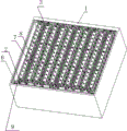
Fig. 1 is the mounting structure schematic diagram of the utility model embodiment mono-.
Fig. 2 is electrokinetic cell of the present utility model and insulation grid mounting structure schematic diagram.
Fig. 3 is the structural representation of battery module of the present utility model.
Embodiment
Embodiment mono-is at Fig. 1, in Fig. 2 and Fig. 3, the utility model provides a kind of pure electric coach quick change battery box battery module combination structure that is applicable to, it is provided with five battery modules and quick change battery box 1, five battery modules are arranged in quick change battery box 1, quick change battery box 1 lower surface is pasted with electrically insulating silicone rubber plate, it is corresponding with battery module that electrically insulating silicone rubber plate is placed on the bottom of battery module, in two outsides of each battery module, be respectively equipped with insulation board I 2 and insulation board II 3, on the top of insulation board I 2, be provided with briquetting I 4, on the top of insulation board II 3, be provided with briquetting II 5, a side at quick change battery box 1 is provided with connecting plate 6, each battery module is connected with quick change battery box 1 with the cooperation that is connected of connecting plate 6 by briquetting I 4, described briquetting I 4 is provided with installing hole I, connecting plate 6 is provided with double-screw bolt 9, each battery module is connected with quick change battery box 1 after inserting installing hole I by double-screw bolt 9.After each battery module is placed side by side by 16 battery insulators, by jockey, is serially connected and forms battery module, described jockey comprises that the both sides that the centre at each insulation grid 8 top is provided with bolt mounting holes I and each insulation grid 8 bottoms are respectively equipped with bolt mounting holes II, bolt mounting holes II is set to counterbore, some battery insulators form battery module by being installed with bolt I 12 and being installed with the rear serial connection of bolt II 13 in bolt mounting holes I in two bolt mounting holes II, if each battery insulator comprises an electrokinetic cell 7 and two insulation grids 8, two insulation grids 8 are encircled a rear formation battery insulator of electrokinetic cell 7, insulation grid 8 is set to glass flame retardant plastics, described insulation grid 8 surroundings are equipped with guide vane end stop 11, the middle part of described insulation grid 8 is provided with U-shaped groove 10, the bottom of insulation grid 8 is arranged on inverted U, the diagonal angle up and down of described each insulation grid 8 is respectively equipped with limited post and spacing hole, two insulation grids 8 are oppositely encircled electrokinetic cell 7 by after being connected of limited post and spacing hole after docking, in the middle of described insulation grid 8, there are five grizzly bars that are parallel to each other and are arranged in parallel, the formation air channel, gap being provided with between grizzly bar.
Embodiment bis-, the utility model provides a kind of pure electric coach quick change battery box battery module combination structure that is applicable to, it is provided with five battery modules and quick change battery box 1, five battery modules are arranged in quick change battery box 1, quick change battery box 1 lower surface is pasted with electrically insulating silicone rubber plate, it is corresponding with battery module that electrically insulating silicone rubber plate is placed on the bottom of battery module, in two outsides of each battery module, be respectively equipped with insulation board I 2 and insulation board II 3, on the top of insulation board I 2, be provided with briquetting I 4, on the top of insulation board II 3, be provided with briquetting II 5, a side at quick change battery box 1 is provided with connecting plate 6, each battery module is connected with quick change battery box 1 with the cooperation that is connected of connecting plate 6 by briquetting II 5, described briquetting II 5 is provided with installing hole II, connecting plate 6 is provided with double-screw bolt 9, each battery module is connected with quick change battery box 1 after inserting installing hole II by double-screw bolt 9, after each battery module is placed side by side by 16 battery insulators, by jockey, is serially connected and forms battery module, described jockey comprises that the both sides that the centre at each insulation grid 8 top is provided with bolt mounting holes I and each insulation grid 8 bottoms are respectively equipped with bolt mounting holes II, bolt mounting holes II is set to counterbore, 16 battery insulators form battery module by being installed with bolt I 12 and being installed with the rear serial connection of bolt II 13 in bolt mounting holes I in two bolt mounting holes II, if each battery insulator comprises an electrokinetic cell 7 and two insulation grids 8, two insulation grids 8 are encircled a rear formation battery insulator of electrokinetic cell 7, insulation grid 8 is set to glass flame retardant plastics, described insulation grid 8 surroundings are equipped with guide vane end stop, the middle part of described insulation grid 8 is provided with U-shaped groove 10, the bottom of insulation grid 8 is arranged on inverted U, the diagonal angle up and down of described each insulation grid 8 is respectively equipped with limited post and spacing hole, two insulation grids 8 are oppositely encircled electrokinetic cell 7 by after being connected of limited post and spacing hole after docking, in the middle of described insulation grid 8, there are five grizzly bars that are parallel to each other and are arranged in parallel, the formation air channel, gap being provided with between grizzly bar.
Claims (10)
1. one kind is applicable to pure electric coach quick change battery box battery module combination structure, it is characterized in that it is provided with some battery modules and quick change battery box (1), some battery modules are arranged in quick change battery box (1), in two outsides of each battery module, be respectively equipped with insulation board I (2) and insulation board II (3), on the top of insulation board I (2), be provided with briquetting I (4), on the top of insulation board II (3), be provided with briquetting II (5), a side at quick change battery box (1) is provided with connecting plate (6), each battery module by briquetting I (4) and connecting plate (6) be connected cooperation or briquetting II (5) is connected with quick change battery box (1) with the cooperation that is connected of connecting plate (6), after each battery module is placed side by side by some battery insulators, by jockey, is serially connected and forms battery module, each battery insulator comprises an electrokinetic cell (7) and two insulation grids (8), two insulation grids (8) form battery insulator after encircling an electrokinetic cell (7).
2. the pure electric coach quick change battery box battery module combination structure that is applicable to according to claim 1, is characterized in that described insulation grid (8) is set to glass flame retardant plastics.
3. the pure electric coach quick change battery box battery module combination structure that is applicable to according to claim 1, it is characterized in that described briquetting I (4) is provided with installing hole I, connecting plate (6) is provided with double-screw bolt (9), and each battery module is connected with quick change battery box (1) after inserting installing hole I by double-screw bolt (9).
4. the pure electric coach quick change battery box battery module combination structure that is applicable to according to claim 1, it is characterized in that described briquetting II (5) is provided with installing hole II, connecting plate (6) is provided with double-screw bolt (9), and each battery module is connected with quick change battery box (1) after inserting installing hole II by double-screw bolt (9).
5. the pure electric coach quick change battery box battery module combination structure that is applicable to according to claim 1, is characterized in that described insulation grid (8) surrounding is equipped with guide vane end stop (11).
6. the pure electric coach quick change battery box battery module combination structure that is applicable to according to claim 1, it is characterized in that described quick change battery box (1) lower surface is pasted with electrically insulating silicone rubber plate, it is corresponding with battery module that electrically insulating silicone rubber plate is placed on the bottom of battery module.
7. the pure electric coach quick change battery box battery module combination structure that is applicable to according to claim 1, is characterized in that the middle part of described insulation grid (8) is provided with U-shaped groove (10), and the bottom of insulation grid (8) is arranged on inverted U.
8. the pure electric coach quick change battery box battery module combination structure that is applicable to according to claim 1, it is characterized in that the both sides that described jockey comprises that the centre at each insulation grid (8) top is provided with bolt mounting holes I and each insulation grid (8) bottom are respectively equipped with bolt mounting holes II, bolt mounting holes II is set to counterbore, and some battery insulators form battery module by serial connection after being installed with bolt I (12) and being installed with bolt II (13) in bolt mounting holes I in two bolt mounting holes II.
9. the pure electric coach quick change battery box battery module combination structure that is applicable to according to claim 1, the diagonal angle up and down that it is characterized in that described each insulation grid (8) is respectively equipped with limited post and spacing hole, and two insulation grids (8) are oppositely encircled electrokinetic cell (7) by after being connected of limited post and spacing hole after docking.
10. the pure electric coach quick change battery box battery module combination structure that is applicable to according to claim 1, is characterized in that having some grizzly bars that are parallel to each other and are arranged in parallel, the formation air channel, gap being provided with in the middle of described insulation grid (8) between grizzly bar.
Priority Applications (1)
| Application Number | Priority Date | Filing Date | Title |
|---|---|---|---|
| CN201320562830.4U CN203481299U (en) | 2013-09-11 | 2013-09-11 | Battery module combined structure suitable for quick-change battery box of pure electric bus |
Applications Claiming Priority (1)
| Application Number | Priority Date | Filing Date | Title |
|---|---|---|---|
| CN201320562830.4U CN203481299U (en) | 2013-09-11 | 2013-09-11 | Battery module combined structure suitable for quick-change battery box of pure electric bus |
Publications (1)
| Publication Number | Publication Date |
|---|---|
| CN203481299U true CN203481299U (en) | 2014-03-12 |
Family
ID=50229568
Family Applications (1)
| Application Number | Title | Priority Date | Filing Date |
|---|---|---|---|
| CN201320562830.4U Expired - Fee Related CN203481299U (en) | 2013-09-11 | 2013-09-11 | Battery module combined structure suitable for quick-change battery box of pure electric bus |
Country Status (1)
| Country | Link |
|---|---|
| CN (1) | CN203481299U (en) |
Cited By (1)
| Publication number | Priority date | Publication date | Assignee | Title |
|---|---|---|---|---|
| CN103515556A (en) * | 2013-09-11 | 2014-01-15 | 江苏春兰清洁能源研究院有限公司 | Battery module combination structure suitable for quick-change battery box of pure electric bus |
-
2013
- 2013-09-11 CN CN201320562830.4U patent/CN203481299U/en not_active Expired - Fee Related
Cited By (2)
| Publication number | Priority date | Publication date | Assignee | Title |
|---|---|---|---|---|
| CN103515556A (en) * | 2013-09-11 | 2014-01-15 | 江苏春兰清洁能源研究院有限公司 | Battery module combination structure suitable for quick-change battery box of pure electric bus |
| CN103515556B (en) * | 2013-09-11 | 2016-01-20 | 江苏春兰清洁能源研究院有限公司 | One is applicable to pure electric coach quick change battery box battery module combination structure |
Similar Documents
| Publication | Publication Date | Title |
|---|---|---|
| CN106058112B (en) | Cylindrical battery module | |
| CN205680721U (en) | A kind of battery modules mounting structure | |
| CN103000845A (en) | Power lithium battery box | |
| CN207183353U (en) | A kind of attachment structure of battery bag casing and single lithium battery | |
| CN205900626U (en) | Novel battery pack | |
| CN202076346U (en) | Lithium battery cell group and power battery box | |
| CN203491319U (en) | Battery pack structure | |
| WO2014198183A1 (en) | Safe intelligent battery pack | |
| CN103515556B (en) | One is applicable to pure electric coach quick change battery box battery module combination structure | |
| CN203456525U (en) | Energy storage battery device | |
| CN204596858U (en) | A kind of battery for electric automobile case | |
| CN203103367U (en) | Iron-lithium battery fixing support | |
| CN105977555B (en) | A kind of modular battery pack system | |
| CN102938452A (en) | Square power battery module combined structure with metal shell | |
| CN216250964U (en) | A battery pack module | |
| CN203071147U (en) | Square power battery module combined structure with metal shell | |
| CN203746995U (en) | Anti-overheating battery module | |
| JP2017507459A (en) | Power terminal assembly for battery module | |
| CN202585578U (en) | Power storage battery module for electric vehicle | |
| CN204045658U (en) | The fixed mount of car battery | |
| CN204792992U (en) | High -speed joint energy storage battery box | |
| CN204441376U (en) | A kind of dynamic lithium battery lug bundle insulation protection structure | |
| CN204077338U (en) | A kind of batteries of electric automobile bag erecting frame | |
| CN102779872B (en) | Solar photovoltaic thin-film junction box | |
| CN201766140U (en) | Power battery pack and battery module |
Legal Events
| Date | Code | Title | Description |
|---|---|---|---|
| GR01 | Patent grant | ||
| GR01 | Patent grant | ||
| CF01 | Termination of patent right due to non-payment of annual fee |
Granted publication date: 20140312 Termination date: 20160911 |
|
| CF01 | Termination of patent right due to non-payment of annual fee |