CN203456841U - Water conservancy project cable connecting apparatus specially used in adverse conditions - Google Patents
Water conservancy project cable connecting apparatus specially used in adverse conditions Download PDFInfo
- Publication number
- CN203456841U CN203456841U CN201320483338.8U CN201320483338U CN203456841U CN 203456841 U CN203456841 U CN 203456841U CN 201320483338 U CN201320483338 U CN 201320483338U CN 203456841 U CN203456841 U CN 203456841U
- Authority
- CN
- China
- Prior art keywords
- cable
- sealing ring
- protective tube
- cap
- connection device
- Prior art date
- Legal status (The legal status is an assumption and is not a legal conclusion. Google has not performed a legal analysis and makes no representation as to the accuracy of the status listed.)
- Expired - Fee Related
Links
- XLYOFNOQVPJJNP-UHFFFAOYSA-N water Substances O XLYOFNOQVPJJNP-UHFFFAOYSA-N 0.000 title abstract description 17
- 230000002411 adverse Effects 0.000 title 1
- 238000007789 sealing Methods 0.000 claims abstract description 55
- 230000001681 protective effect Effects 0.000 claims abstract description 33
- 239000010963 304 stainless steel Substances 0.000 claims abstract description 5
- 229910000589 SAE 304 stainless steel Inorganic materials 0.000 claims abstract description 5
- -1 polytetrafluoroethylene Polymers 0.000 claims abstract description 4
- 229920001343 polytetrafluoroethylene Polymers 0.000 claims abstract description 4
- 239000004810 polytetrafluoroethylene Substances 0.000 claims abstract description 4
- 230000007797 corrosion Effects 0.000 abstract description 3
- 238000005260 corrosion Methods 0.000 abstract description 3
- 238000012544 monitoring process Methods 0.000 description 10
- 238000000034 method Methods 0.000 description 5
- 238000010586 diagram Methods 0.000 description 3
- 230000000694 effects Effects 0.000 description 3
- 239000003292 glue Substances 0.000 description 3
- 238000004519 manufacturing process Methods 0.000 description 3
- 238000009434 installation Methods 0.000 description 2
- 210000001503 joint Anatomy 0.000 description 2
- 238000003032 molecular docking Methods 0.000 description 2
- 239000004033 plastic Substances 0.000 description 2
- 238000004073 vulcanization Methods 0.000 description 2
- 230000009286 beneficial effect Effects 0.000 description 1
- 238000010276 construction Methods 0.000 description 1
- 230000007812 deficiency Effects 0.000 description 1
- 238000009413 insulation Methods 0.000 description 1
- 239000000463 material Substances 0.000 description 1
- 230000035899 viability Effects 0.000 description 1
Images


Landscapes
- Cable Accessories (AREA)
Abstract
本实用新型公开的是一种耐高压、耐高低温、耐腐蚀、耐抗拉拽的新型恶劣环境下专用水工电缆连接装置,其部件包括电缆并帽、平垫、密封圈、护管。其中并帽、平垫、护管均采用304不锈钢材质制造,密封圈采用聚四氟乙烯材质制造。上所述恶劣环境下专用水工电缆连接便捷装置是在高水压下实现电缆与电缆之间可靠连接的一种密封装置。由于采用两端并帽挤压密封圈,充分利用密封圈在弹性范围内有效的变形,从而使连接后电缆接头处在护管内与电缆线、密封圈与护管紧密连接融为一体为核心,保证了该装置能在3~5aMP水压力恶劣环境下长期稳定工作(其3~5aMP压力=300~500米水位深度)。
The utility model discloses a new type hydraulic cable connection device specially used in harsh environments with high pressure resistance, high and low temperature resistance, corrosion resistance and drag resistance. Among them, the cap, flat pad and protective tube are all made of 304 stainless steel, and the sealing ring is made of polytetrafluoroethylene. The above-mentioned special hydraulic cable connection convenient device in harsh environment is a sealing device that can realize reliable connection between cables under high water pressure. Due to the use of both ends to squeeze the sealing ring, the effective deformation of the sealing ring in the elastic range is fully utilized, so that the cable joint is in the protective tube after connection and the cable, the sealing ring and the protective tube are tightly connected and integrated as the core. It is guaranteed that the device can work stably for a long time under the harsh environment of 3-5aMP water pressure (the pressure of 3-5aMP=300-500m water level depth).
Description
技术领域 technical field
本实用新型属于水利工程技术领域,特别是一种用于大坝、深水区、海域电缆与电缆之间对接在高水位下一种密封装置。 The utility model belongs to the technical field of water conservancy engineering, in particular to a sealing device used for docking between cables in dams, deep water areas and sea areas under high water levels. the
背景技术 Background technique
在工程管理中,用于河道、水库、大坝、深水区、海域等的监测设备是各地有关部门十分关注的工作。恶劣环境下专用水工电缆连接便捷装置是一种常用的监测仪器电缆不可缺少的一部分装置,其工作原理是在高水压下实现电缆与电缆之间可靠连接的一种密封装置。 In project management, the monitoring equipment used in river courses, reservoirs, dams, deep water areas, sea areas, etc. is the work that the relevant departments in various places are very concerned about. The special hydraulic cable connection convenient device in harsh environment is an indispensable part of the commonly used monitoring instrument cable. Its working principle is a sealing device that realizes reliable connection between cables under high water pressure. the
现有的恶劣环境下专用水工电缆连接便捷装置是监测仪器电缆与电缆对接一种主要装置,一般采用热缩管加猪皮胶方式、塑料套管加注胶方式、硫化方式等对接,其中前两种方式在使用时随时漂与温漂变化,塑料易老化,胶与电缆之间不能融为一体,在收放电缆拉拽中也易脱落;后一种方式在使用时要有专用硫化设备,成本也较高,施工也较复杂,收放电缆拉拽中也易脱落,对电缆的对接成活力影响比较大,稳定性也较差。以上几种电缆对接稳定性存在一定的问题,而且也大大增加了生产成本。 The existing convenient device for connecting special hydraulic cables in harsh environments is a major device for connecting the cables of monitoring instruments. Generally, heat shrinkable tubes are added with pigskin glue, plastic sleeves are filled with glue, and vulcanization methods are used for docking. The first two methods drift and change at any time during use, the plastic is easy to age, the glue and the cable cannot be integrated, and it is easy to fall off when the cable is pulled; the latter method must be used for special vulcanization The cost of equipment is also high, and the construction is also relatively complicated. The retractable cable is also easy to fall off during pulling, which has a relatively large impact on the viability of the cable butt joint, and the stability is also poor. There are certain problems in the butt joint stability of the above types of cables, and the production cost is also greatly increased. the
实用新型内容 Utility model content
针对现有技术上存在的不足,本实用新型的目的是提供一种耐高水压、耐高低温、耐腐蚀、耐抗拉拽,稳定性好可靠性及高的专用恶劣环境下专用水工电缆连接装置,可以作为电缆与电缆连接装置主要的一部分,可大大减少了人员的劳动强度,以达到提高产品质量、生产效率、降低生产成本的目的。 Aiming at the deficiencies existing in the prior art, the purpose of this utility model is to provide a special-purpose water conservancy equipment for harsh environments with high water pressure resistance, high and low temperature resistance, corrosion resistance, pull resistance, good stability and high reliability. The cable connection device can be used as the main part of the cable and cable connection device, which can greatly reduce the labor intensity of personnel, so as to achieve the purpose of improving product quality, production efficiency and reducing production cost. the
为了实现上述目的,本实用新型是通过如下的技术方案来实现: In order to achieve the above object, the utility model is realized through the following technical solutions:
一种恶劣环境下专用水工电缆连接装置,包括第一电缆并帽,第一电缆线的一端穿过第一电缆并帽并与之固定,第二电缆线的一端穿过第二电缆并帽并与之固定,第一电缆并帽或第二电缆并帽与护管两端通过螺丝纹连接。 A special hydraulic cable connection device for harsh environments, including a first cable parallel cap, one end of the first cable thread passes through the first cable cap and is fixed thereto, and one end of the second cable thread passes through the second cable cap And fixed with it, the first cable parallel cap or the second cable parallel cap and the two ends of the protective tube are connected by screw threads. the
作为优选,所述电缆并帽与护管之间设有密封组件。 Preferably, a sealing assembly is provided between the cable cap and the protective tube. the
作为优选,所述密封组件包括平垫和密封圈,其位置依次为电缆并帽、平垫、密封圈、平垫。 Preferably, the sealing assembly includes a flat gasket and a sealing ring, the positions of which are the cable cap, the flat gasket, the sealing ring, and the flat gasket in sequence. the
作为优选,所述密封圈分别设置在护管两端,每端为两个。 Preferably, the sealing rings are respectively arranged at both ends of the protective pipe, and there are two sealing rings at each end. the
作为优选,所述的第一电缆并帽、平垫、护管均采用304不锈钢材质制造。 Preferably, the first cable cap, flat pad, and protective tube are all made of 304 stainless steel. the
作为优选,所述的密封圈采用聚四氟乙烯材质制造。 Preferably, the sealing ring is made of polytetrafluoroethylene. the
所述电缆并帽、平垫、护管、密封圈可根据任何电缆规格尺寸来制造生产。 The cable caps, flat pads, protective tubes, and sealing rings can be produced according to any cable specification and size. the
本实用新型的有益之处在于:1.采用两端并帽挤压密封圈,充分利用密封圈在弹性范围内有效的变形,从而使连接后电缆接头处在护管内与电缆线、密封圈与护管紧密连接融为一体为核心,保证了该装置能在3~5aMP水压力恶劣环境下长期稳定工作(其3~5aMP压力=300~500米水位深度);2.采用合适的材料,使得本实用新型不受高低温与腐蚀性环境的影响,具有稳定性较好、成本也较低和公差小,同时利用密封圈部位增加了密封性;3.每次的加工件都能保证在一个恒定的公差尺寸范围内,质量有了稳定的保证,而且安装方便,最大限度地提高了产品的性能价格比和可用性。 The utility model is beneficial in that: 1. The two ends are used to squeeze the sealing ring, and the effective deformation of the sealing ring in the elastic range is fully utilized, so that the cable joint is in the protective tube after connection and is connected with the cable wire, the sealing ring and the sealing ring. The tight connection of the protective pipe is integrated as the core, which ensures that the device can work stably for a long time under the harsh environment of 3-5aMP water pressure (the pressure of 3-5aMP=300-500m water level depth); 2. Adopt suitable materials, so that The utility model is not affected by high and low temperature and corrosive environments, and has good stability, low cost and small tolerance. At the same time, the sealing ring is used to increase the sealing performance; 3. Each processing part can be guaranteed to be in one Within the constant tolerance size range, the quality is guaranteed to be stable, and the installation is convenient, which maximizes the performance-price ratio and usability of the product. the
下面结合附图和具体实施方式来详细说明本新型实用新型。 The utility model of the present invention will be described in detail below in conjunction with the accompanying drawings and specific embodiments. the
附图说明 Description of drawings
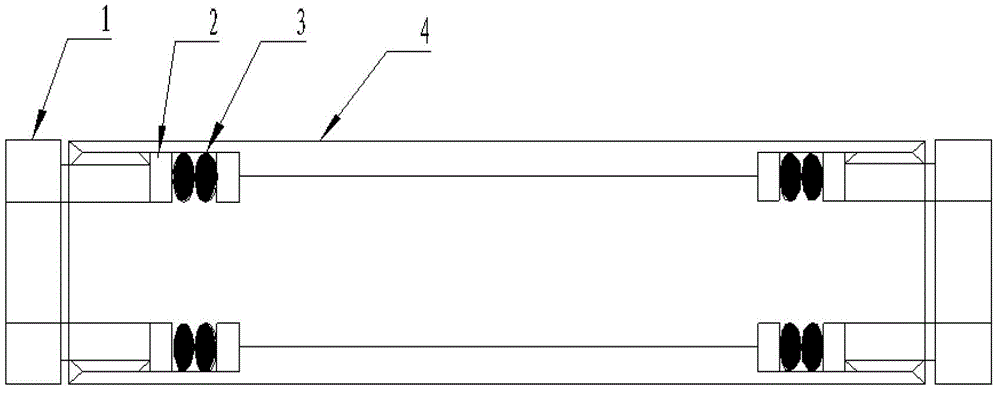
图1为本新型实用新型的电缆连接装置剖面图; Fig. 1 is the sectional view of the cable connection device of the utility model of the present invention;
图2为本新型实用新型的电缆连接装置组装示意图一; Figure 2 is a schematic diagram of the assembly of the cable connection device of the new utility model;
图3为本新型实用新型的电缆连接装置组装示意图二; Fig. 3 is the second assembly schematic diagram of the cable connection device of the present invention;
图4为本新型实用新型的电缆连接装置组装示意图三。 Fig. 4 is a third schematic diagram of the assembly of the cable connection device of the present invention. the
图中,1.第一电缆并帽;2.第一平垫;3.第一密封圈;4.护管;5.第二平垫;6.第二密封圈;7.第二电缆并帽;8.第一电缆线;9.第二电缆线;10.电缆线接头处。 In the figure, 1. The first cable parallel cap; 2. The first flat gasket; 3. The first sealing ring; 4. Protective tube; 5. The second flat gasket; 6. The second sealing ring; 7. The second cable parallel Cap; 8. The first cable; 9. The second cable; 10. The cable joint. the
具体实施方式 Detailed ways
为使本实用新型实现的技术手段、创作特征、达成目的与功效易于明白了解,下面结合具体实施方式,进一步阐述本新型实用新型。 In order to make the technical means, creative features, goals and effects achieved by the utility model easy to understand, the utility model will be further elaborated below in conjunction with specific embodiments. the
结合图1,本新型的一种恶劣环境下专用水工电缆连接装置包括第一电缆并帽(1),第一电缆线(8)的一端穿过第一电缆并帽(1)并与之固定,第二电缆线(9)的一端穿过第二电缆并帽(7)并与之固定,电缆并帽与护管(4)之间设有平垫和密封圈,其位置依次为电缆并帽、平垫、密封圈、平垫。图中部件电缆并帽分别在护管两端工作,作用是在电缆接头连接好后,经过电缆接头处电缆、第一平垫(2)、第一密封圈(3)与护管(4),通过第一电缆并帽(1)与护管(4) 上螺丝纹连接,同时挤压密封圈起到固定电缆,防止电缆拉拽中脱落,使电缆线与第一密封圈(3)、护管(4)紧密连接融为一体;密封圈分别工作在护管(4)两端,每端为两个,作用是通过第一电缆并帽(1)工作时挤压第一密封圈(3),从而使第一密封圈(3)在范围内有效的变形与电缆线、护管(4)紧密连接融为一体,起到较好的密封作用;护管(4)的作用是保护电缆接头处电缆与电缆连接有效空间,防止电缆连接处进水。 With reference to Figure 1, the new type of special hydraulic cable connection device for harsh environments includes a first cable parallel cap (1), and one end of the first cable line (8) passes through the first cable parallel cap (1) and connects with it Fixed, one end of the second cable (9) passes through the second cable and cap (7) and is fixed with it, there is a flat gasket and a sealing ring between the cable and the protective tube (4), and its position is the cable And caps, flat pads, sealing rings, flat pads. In the figure, the cables and caps of the components work at both ends of the protective tube respectively. The function is that after the cable joint is connected, it passes through the cable at the cable joint, the first flat pad (2), the first sealing ring (3) and the protective tube (4). , through the first cable parallel cap (1) and the upper screw thread of the protective tube (4), and at the same time squeeze the sealing ring to fix the cable, preventing the cable from falling off during pulling, so that the cable and the first sealing ring (3), The protective tube (4) is tightly connected and integrated; the sealing rings work at both ends of the protective tube (4) respectively, and each end is two, and the function is to squeeze the first sealing ring ( 3), so that the first sealing ring (3) can be effectively deformed within the range and tightly connected with the cable and the protective tube (4) to form a good sealing effect; the role of the protective tube (4) is to protect The effective space between the cable and the cable connection at the cable joint prevents water from entering the cable connection. the
作为本实用新型的优选方案,本新型的恶劣环境下专用水工电缆连接装置中第一电缆并帽(1)、平垫(2)、护管(4)是采用304不锈钢材质制造。密封圈采用聚四氟乙烯材质制造。 As a preferred solution of the present utility model, the first cable joint cap (1), flat pad (2) and protective tube (4) in the special hydraulic cable connection device for harsh environments of the present invention are made of 304 stainless steel. The sealing ring is made of polytetrafluoroethylene. the
结合图2-4,本新型的恶劣环境下专用水工电缆连接装置在安装时,其安装要将电缆线拉到与监测仪器输出电缆同一位置,进行两端电缆线头接线前准备工作。其详细安装要求方法如下: With reference to Figures 2-4, when installing the special hydraulic cable connection device for harsh environments of the present invention, the cable should be pulled to the same position as the output cable of the monitoring instrument, and the preparation work before wiring the cable ends at both ends should be carried out. The detailed installation requirements are as follows:
1、将需要延长电缆线的监测仪器输出接头处与连接电缆线接头处杂物处理干净; 1. Clean up the debris at the output joint of the monitoring instrument that needs to be extended and at the joint of the connecting cable;
2、将监测仪器用专用测量设备做好接线前测量,并且做好仪器测值记录; 2. Use special measuring equipment to measure the monitoring instrument before wiring, and make a record of the measured value of the instrument;
3、将监测仪器编号与需要连接电缆线两端做好标识,并且同时做好记录; 3. Mark the serial number of the monitoring instrument and the two ends of the cable to be connected, and make a record at the same time;
4、将需要延长电缆线的监测仪器输出接头处,按照图2顺序,安装第一电缆并帽(1)一支,一支第一平垫(2),第一密封圈(3)两支,另一支第一平垫(2); 4. At the output joint of the monitoring instrument that needs to extend the cable, install the first cable cap (1), one first flat pad (2), and two first sealing rings (3) according to the sequence shown in Figure 2 , another first flat pad (2);
5、将需要连接电缆线接头处(10),按照图2顺序,安装第二电缆并帽(7)一支,一支第二平垫(5),第二密封圈(6)两支,另一支第二平垫(5),护管(4)一支; 5. To connect the cable joint (10), install the second cable parallel cap (7), one second flat pad (5), two second sealing rings (6) according to the order shown in Figure 2, Another second flat pad (5), one protective tube (4);
6、将恶劣环境下专用水工电缆连接装置部件安装好后,参见图3,对多芯电缆线一一对接,并且做好绝缘保护; 6. After installing the parts of the special hydraulic cable connection device in harsh environments, see Figure 3, connect the multi-core cables one by one, and do a good job of insulation protection;
7、在电缆对接与绝缘保护好后,再参见图4,将护管与两端电缆并帽螺纹对应连接,并且用两把扳手拎紧,充分利用密封圈在弹性范围内有效的变形,从而使连接后电缆接头处在护管内与电缆线、密封圈与护管紧密连接融为一体,实现在高水压下电缆与电缆之间可靠连接的一种密封装置; 7. After the cables are connected and insulated, refer to Figure 4 again, connect the protective tube with the cap threads of the cables at both ends, and tighten them with two wrenches, making full use of the effective deformation of the sealing ring within the elastic range, so that After the connection, the cable joint is in the protective tube, and the cable, the sealing ring and the protective tube are tightly connected and integrated, and a sealing device that realizes a reliable connection between the cable and the cable under high water pressure;
8、在密封装置安装好后,再次对监测仪器用专用测量设备做好接线后测量,并且做好仪器测值记录。 8. After the sealing device is installed, measure the monitoring instrument with special measuring equipment after wiring, and make a record of the measured value of the instrument. the
本新型的原理:在监测仪器输出电缆线不够长时,需要延长,在电缆线与电缆线对接时,此恶劣环境下专用水工电缆连接便捷装置的电缆并帽作用是在电缆接头连接好后,经过电缆接头处电缆、平垫、密封圈与护管,通过电缆并帽与护管上螺丝纹连接,同时挤压密封圈,充分利用密封圈在弹性范围内有效的变形,起到固定电缆,防止电缆拉拽中脱落,使电缆线、密封圈与护管紧密连接融为一体;平垫作用是保护密封圈在电缆并帽工作时损坏密封圈;护管作用是保护电缆接头处电缆与电缆连接有效空间与电缆连接处进水;密封圈作用是通过电缆并帽工作时挤压密封圈,从而使密封圈在范围内有效的变形与电缆线、护管紧密连接融为一体,起到较好的密封作用;起到耐高压、耐高低温、耐腐蚀、耐抗拉拽,是电缆与电缆之间对接在高水位下的一种密封装置。 The principle of this new model: When the output cable of the monitoring instrument is not long enough, it needs to be extended. When the cable is connected to the cable, the function of the cable capping function of the special hydraulic cable connection convenient device in this harsh environment is after the cable connector is connected. , pass through the cable, flat gasket, sealing ring and protective tube at the cable joint, connect the screw thread on the protective tube through the cable cap, and squeeze the sealing ring at the same time, making full use of the effective deformation of the sealing ring within the elastic range to fix the cable , to prevent the cable from falling off during pulling, so that the cable, the sealing ring and the protective tube are tightly connected and integrated; the function of the flat pad is to protect the sealing ring from being damaged when the cable is connected to the cap; the function of the protective tube is to protect the cable at the cable joint. Water enters the effective space of the cable connection and the cable connection; the function of the sealing ring is to squeeze the sealing ring when the cable is connected to the cap, so that the sealing ring can be effectively deformed within the range and integrated with the tight connection of the cable and the protective tube to play a role. Good sealing effect; high pressure resistance, high and low temperature resistance, corrosion resistance, and pull resistance. It is a sealing device for connecting cables at high water levels. the
本新型的恶劣环境下专用水工电缆连接便捷装置与传统电缆连接方式相比具有显著优点,具体如表1: Compared with the traditional cable connection method, this new type of convenient device for hydraulic cable connection in harsh environments has significant advantages, as shown in Table 1:
表1 
以上描述了本实用新型的基本原理和主要特征以及本实用新型的优点。本实用新型不受上述实施例的限制,上述实施例和说明书中描述的只是说明本实用新型的原理,在不脱离本实用新型精神和范围的前提下,本实用新型还会有各种变化和改进,这些变化和改进都落入要求保护的本新型实用新型范围内。本实用新型要求保护范围由所附的权利要求书及其等效物界定。 The basic principles and main features of the utility model and the advantages of the utility model have been described above. The utility model is not limited by the above-mentioned embodiment, and what described in the above-mentioned embodiment and the description is only to illustrate the principle of the utility model, and the utility model also has various changes and changes without departing from the spirit and scope of the utility model. Improvements, these changes and improvements all fall within the scope of the claimed utility model of the present invention. The scope of protection required by the utility model is defined by the appended claims and their equivalents. the
Claims (7)
Priority Applications (1)
| Application Number | Priority Date | Filing Date | Title |
|---|---|---|---|
| CN201320483338.8U CN203456841U (en) | 2013-08-08 | 2013-08-08 | Water conservancy project cable connecting apparatus specially used in adverse conditions |
Applications Claiming Priority (1)
| Application Number | Priority Date | Filing Date | Title |
|---|---|---|---|
| CN201320483338.8U CN203456841U (en) | 2013-08-08 | 2013-08-08 | Water conservancy project cable connecting apparatus specially used in adverse conditions |
Publications (1)
| Publication Number | Publication Date |
|---|---|
| CN203456841U true CN203456841U (en) | 2014-02-26 |
Family
ID=50136694
Family Applications (1)
| Application Number | Title | Priority Date | Filing Date |
|---|---|---|---|
| CN201320483338.8U Expired - Fee Related CN203456841U (en) | 2013-08-08 | 2013-08-08 | Water conservancy project cable connecting apparatus specially used in adverse conditions |
Country Status (1)
| Country | Link |
|---|---|
| CN (1) | CN203456841U (en) |
Cited By (2)
| Publication number | Priority date | Publication date | Assignee | Title |
|---|---|---|---|---|
| CN107294014A (en) * | 2017-07-24 | 2017-10-24 | 广州番禺电缆集团有限公司 | A kind of low-voltage cable joint prosthetic device and low-voltage cable joint restorative procedure |
| CN108879581A (en) * | 2018-06-27 | 2018-11-23 | 中国石油天然气股份有限公司 | Cable connection device and cable connection method |
-
2013
- 2013-08-08 CN CN201320483338.8U patent/CN203456841U/en not_active Expired - Fee Related
Cited By (2)
| Publication number | Priority date | Publication date | Assignee | Title |
|---|---|---|---|---|
| CN107294014A (en) * | 2017-07-24 | 2017-10-24 | 广州番禺电缆集团有限公司 | A kind of low-voltage cable joint prosthetic device and low-voltage cable joint restorative procedure |
| CN108879581A (en) * | 2018-06-27 | 2018-11-23 | 中国石油天然气股份有限公司 | Cable connection device and cable connection method |
Similar Documents
| Publication | Publication Date | Title |
|---|---|---|
| CN204372558U (en) | A kind of bilayer sleeve heat supply pipeline leak detecting device | |
| CN204559072U (en) | Submerged type differential pressure transmitter cable sealing device | |
| CN206846132U (en) | A kind of hydraulic engineering pipeline protection cover | |
| CN204344118U (en) | The syndeton of a kind of downhole instrument and coupling | |
| CN205603624U (en) | Converter detects sublance | |
| CN203848875U (en) | Flue cross section flow field test device | |
| CN204177354U (en) | A kind of arc measurement device of heavy caliber monitoring pipeline | |
| CN207570611U (en) | Compression high-voltage electromagnetic flowmeter inside and outside a kind of immersion | |
| CN206772497U (en) | Optical fiber cable infiltration detecting system | |
| CN206943618U (en) | A kind of special self sealss of novel skirting type field of heating are to silk attachment means | |
| CN205001869U (en) | Underground heat supply pipeline expansion joint equipment | |
| CN203685345U (en) | Engine oil level gauge guide pipe | |
| CN203942250U (en) | A kind of submerged cable protecting pipe | |
| CN204403633U (en) | A kind of transport pipe connecting sleeve | |
| CN204241029U (en) | Integrated pressure temperature measurement system | |
| CN209603883U (en) | A kind of geothermal well pumps up water with flexible pipe device | |
| CN207019720U (en) | Integrated measuring piecing devices for water-tight equipment | |
| CN204439155U (en) | A kind of novel gas header | |
| CN204947545U (en) | Spool protective device is exposed on a kind of electrical engineering ground | |
| CN204313895U (en) | Metal pipe float flow meter | |
| CN215000174U (en) | Plugging fixing device of water pressure measuring instrument under many conditions | |
| CN203908614U (en) | Fully waterproof type amplifier for liquid turbine flowmeter | |
| CN221405505U (en) | Reference electrode quick assembly disassembly device for logging | |
| CN104406712A (en) | 10kV cable distributed optical fiber temperature measurement method | |
| CN204114285U (en) | A pressure detection device |
Legal Events
| Date | Code | Title | Description |
|---|---|---|---|
| C14 | Grant of patent or utility model | ||
| GR01 | Patent grant | ||
| CF01 | Termination of patent right due to non-payment of annual fee |
Granted publication date: 20140226 Termination date: 20210808 |
|
| CF01 | Termination of patent right due to non-payment of annual fee |