CN203438065U - Swing mechanism for sanding machine - Google Patents
Swing mechanism for sanding machine Download PDFInfo
- Publication number
- CN203438065U CN203438065U CN201320553370.9U CN201320553370U CN203438065U CN 203438065 U CN203438065 U CN 203438065U CN 201320553370 U CN201320553370 U CN 201320553370U CN 203438065 U CN203438065 U CN 203438065U
- Authority
- CN
- China
- Prior art keywords
- swing
- self
- ball bearing
- aligning ball
- eccentric
- Prior art date
- Legal status (The legal status is an assumption and is not a legal conclusion. Google has not performed a legal analysis and makes no representation as to the accuracy of the status listed.)
- Expired - Fee Related
Links
- 230000003044 adaptive effect Effects 0.000 claims description 18
- 230000001681 protective effect Effects 0.000 claims description 12
- 230000006978 adaptation Effects 0.000 claims description 9
- 238000004519 manufacturing process Methods 0.000 abstract description 4
- 230000005540 biological transmission Effects 0.000 abstract 3
- 230000009286 beneficial effect Effects 0.000 abstract 1
- 238000009434 installation Methods 0.000 description 3
- 230000007812 deficiency Effects 0.000 description 1
- 230000000694 effects Effects 0.000 description 1
- 238000005516 engineering process Methods 0.000 description 1
- 238000004321 preservation Methods 0.000 description 1
Images


Landscapes
- Finish Polishing, Edge Sharpening, And Grinding By Specific Grinding Devices (AREA)
Abstract
The utility model discloses a swing mechanism for a sanding machine. The swing mechanism comprises a drive part, a transmission part and a swing frame body. The drive part drives the transmission part to rotate and the swing frame body to swing. The transmission part comprises a rotating shaft, an eccentric swing block and a swing arm. The head end of the rotating shaft and the drive part are installed in a fit mode. The tail end of the rotating shaft and the head end of the eccentric swing block are installed in a fit mode. The tail end of the eccentric swing block and the head end of the swing arm are installed in a fit mode. The tail end of the swing arm and the swing frame body are installed in a fit mode. The swing frame body can swing, an original eccentric shaft of a single structure is replaced, the manufacturing cost and difficulty are lowered, and therefore the use cost of the sanding machine is lowered, and the swing mechanism is beneficial for development of enterprises.
Description
Technical field
The utility model relates to the mechanism that a kind of sander is used, the swing mechanism that particularly a kind of sander is used.
Background technology
At present, the swing mechanism major part that sander is used is at present all to utilize electric machine rotation deboost axle, and deboost axle is eccentric shaft, and eccentric shaft is connected with swing support body and drives swing support body to swing by eccentric shaft.Yet the processing cost of this eccentric shaft and difficulty are quite high, thereby the cost of manufacture of raising sander is unfavorable for the development of enterprise.
Summary of the invention
The purpose of this utility model is to overcome the deficiencies in the prior art, provides a kind of compact conformation effectively to cut down finished cost and the difficulty swing mechanism that the sander of stable practicality is used again.
Goal of the invention of the present utility model is achieved in that the swing mechanism that a kind of abrasive machine is used, comprise driver part, drive disk assembly and swing support body, driver part drives when driving drive disk assembly to rotate and swings support body swing, wherein, described drive disk assembly comprises turning cylinder, eccentric swing piece and swing arm, turning cylinder head end and driver part are adaptive to be installed, turning cylinder end and eccentric swing piece head end are adaptive to be installed, eccentric swing piece end and swing arm head end are adaptive to be installed, and swing arm end is installed with swing support body is adaptive.
According to above-mentioned, be optimized, be provided with the first self-aligning ball bearing for driving eccentric swing piece to swing between described turning cylinder end and eccentric swing piece, the first self-aligning ball bearing adaptation is set on turning cylinder and adaptation is installed on eccentric swing piece.
According to above-mentioned, be optimized, described eccentric swing piece is provided with and the adaptive installing hole of installing of the first self-aligning ball bearing.
According to above-mentioned, be optimized, described the first self-aligning ball bearing is provided with protective jacket, and protective jacket is set on the first self-aligning ball bearing.
According to above-mentioned, be optimized, between being connected with swing arm, described eccentric swing piece end is provided with the second self-aligning ball bearing for driving swing arm to swing, on the second self-aligning ball bearing, be useful on the connecting axle that connects swing arm, connecting axle one end is connected on the second self-aligning ball bearing, and the connecting axle other end is connected on swing arm.
According to above-mentioned, be optimized, described eccentric swing piece is provided with and the adaptive fixing hole of installing of the second self-aligning ball bearing.
According to above-mentioned, be optimized, described the second self-aligning ball bearing is provided with protective sleeve, and protective sleeve is set on the second self-aligning ball bearing.
According to above-mentioned, be optimized, described driver part comprises reducing motor, and the head end adaptation of reducing motor and turning cylinder is installed and driven turning cylinder to rotate.
The swing mechanism that in the relative prior art of the utility model, sander is used, its advantage is, by by the respective outer side edges of turning cylinder, eccentric swing piece and swing arm, realize the swing that swings support body, the eccentric shaft that replaces original single structure, reduce cost of manufacture and difficulty, thereby reduce the use cost of sander, be conducive to enterprise development.
Accompanying drawing explanation
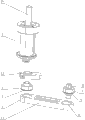
Fig. 1 is the structural representation of the utility model embodiment.
Fig. 2 is the structural representation of the drive disk assembly of the utility model embodiment.
Fig. 3 is the decomposing schematic representation of the drive disk assembly of the utility model embodiment.
The specific embodiment
Below in conjunction with accompanying drawing, the utility model will be further described.
According to shown in Fig. 1 to Fig. 3, the swing mechanism that a kind of sander described in the utility model is used, it comprises driver part 1, drive disk assembly 2 and swings support body 3, in the time of driver part 1 driving drive disk assembly 2 rotation, drives swing support body 3 to swing.Wherein, described drive disk assembly 2 comprises turning cylinder 21, eccentric swing piece 22 and swing arm 23, turning cylinder 21 head ends and the adaptive installation of driver part 1, turning cylinder 21 ends and the adaptive installation of eccentric swing piece 22 head ends, eccentric swing piece 22 ends and the adaptive installation of swing arm 23 head ends, swing arm 23 ends are installed with swing support body 3 is adaptive.According to practical application, driver part 1 comprises reducing motor 11, and reducing motor 11 is installed with the head end adaptation of turning cylinder 21 and driven turning cylinder 21 to rotate.; when reducing motor 11 starts; it drives turning cylinder 21 to rotate; eccentric swing piece 22 is along with turning cylinder 21 rotates and pulls swing arm 23 to swing; thereby drive swing support body 3 to swing; the eccentric shaft that replaces single structure, reduces cost of manufacture and difficulty, thereby reduces the use cost of sander.
According to above-mentioned, be optimized, with reference to shown in Fig. 2 to Fig. 3, between turning cylinder 21 ends and eccentric swing piece 22, be provided with the first self-aligning ball bearing 4 for driving eccentric swing piece 22 to swing, eccentric swing piece 22 is provided with and is set on turning cylinder 21 with adaptive installing hole 5, the first self-aligning ball bearing 4 adaptations of installing of the first self-aligning ball bearing 4 and adaptation is installed on eccentric swing piece 22.And, between being connected with swing arm 23, described eccentric swing piece 22 ends are provided with the second self-aligning ball bearing 7 for driving swing arm 23 to swing, on the second self-aligning ball bearing 7, be useful on the connecting axle 8 that connects swing arm 23, eccentric swing piece 22 is provided with and the adaptive fixing hole 9 of installing of the second self-aligning ball bearing 7.Connecting axle 8 one end are connected on the second self-aligning ball bearing 7, and connecting axle 8 other ends are connected on swing arm 23.When starting, reducing motor 11 drives turning cylinder 21 to rotate, the first self-aligning ball bearing 4 is along with turning cylinder 21 rotates and drives eccentric swing piece 22 to swing, being installed on bias shakes corresponding first self-aligning ball bearing 4 swings of the second self-aligning ball bearing 7 of piece and rotates, thereby drive swing arm 23 to swing, and then drive swing support body 3 to swing, and compact conformation, stable.
In addition; described the first self-aligning ball bearing 4 is provided with protective jacket 6; the second self-aligning ball bearing 7 is provided with protective sleeve 10; protective jacket 6 and protective sleeve 10 be set with on the first self-aligning ball bearing 4 with the second self-aligning ball bearing 7 on; as shown in Figure 3; effectively reduce the wearing and tearing when rotating of the first self-aligning ball bearing 4 and the second self-aligning ball bearing 7, really the service property (quality) of capital preservation product.
Above-mentioned specific embodiment is only the good specific embodiment of the utility model effect, and the swing mechanism that all sanders identical with this structure or that be equal to are used, all in the application's protection domain.
Claims (8)
1. the swing mechanism that abrasive machine is used, comprise driver part (1), drive disk assembly (2) and swing support body (3), driver part (1) drives when driving drive disk assembly (2) to rotate and swings support body (3) swing, it is characterized in that: described drive disk assembly (2) comprises turning cylinder (21), eccentric swing piece (22) and swing arm (23), turning cylinder (21) head end and driver part (1) are adaptive to be installed, turning cylinder (21) end and eccentric swing piece (22) head end are adaptive to be installed, eccentric swing piece (22) end and swing arm (23) head end are adaptive to be installed, swing arm (23) end is installed with swing support body (3) is adaptive.
2. the swing mechanism that abrasive machine is used according to claim 1, it is characterized in that: between described turning cylinder (21) end and eccentric swing piece (22), be provided with the first self-aligning ball bearing (4) for driving eccentric swing piece (22) to swing, the first self-aligning ball bearing (4) adaptation is set in the upper also adaptation of turning cylinder (21) and is installed on eccentric swing piece (22).
3. the swing mechanism that abrasive machine is used according to claim 2, is characterized in that: described eccentric swing piece (22) is provided with and the adaptive installing hole (5) of installing of the first self-aligning ball bearing (4).
4. the swing mechanism that abrasive machine is used according to claim 3, is characterized in that: described the first self-aligning ball bearing (4) is provided with protective jacket (6), and protective jacket (6) is set on the first self-aligning ball bearing (4).
5. the swing mechanism that abrasive machine is used according to claim 1, it is characterized in that: described eccentric swing piece (22) end is provided with the second self-aligning ball bearing (7) for driving swing arm (23) to swing between being connected with swing arm (23), on the second self-aligning ball bearing (7), be useful on the connecting axle (8) that connects swing arm (23), it is upper that connecting axle (8) one end is connected in the second self-aligning ball bearing (7), and connecting axle (8) other end is connected on swing arm (23).
6. the swing mechanism that abrasive machine is used according to claim 5, is characterized in that: described eccentric swing piece (22) is provided with and the adaptive fixing hole (9) of installing of the second self-aligning ball bearing (7).
7. the swing mechanism that abrasive machine is used according to claim 6, is characterized in that: described the second self-aligning ball bearing (7) is provided with protective sleeve (10), and protective sleeve (10) is set on the second self-aligning ball bearing (7).
8. the swing mechanism that abrasive machine is used according to claim 1, is characterized in that: described driver part (1) comprises reducing motor (11), and reducing motor (11) is installed and drives turning cylinder (21) to rotate with the head end adaptation of turning cylinder (21).
Priority Applications (1)
| Application Number | Priority Date | Filing Date | Title |
|---|---|---|---|
| CN201320553370.9U CN203438065U (en) | 2013-09-07 | 2013-09-07 | Swing mechanism for sanding machine |
Applications Claiming Priority (1)
| Application Number | Priority Date | Filing Date | Title |
|---|---|---|---|
| CN201320553370.9U CN203438065U (en) | 2013-09-07 | 2013-09-07 | Swing mechanism for sanding machine |
Publications (1)
| Publication Number | Publication Date |
|---|---|
| CN203438065U true CN203438065U (en) | 2014-02-19 |
Family
ID=50089139
Family Applications (1)
| Application Number | Title | Priority Date | Filing Date |
|---|---|---|---|
| CN201320553370.9U Expired - Fee Related CN203438065U (en) | 2013-09-07 | 2013-09-07 | Swing mechanism for sanding machine |
Country Status (1)
| Country | Link |
|---|---|
| CN (1) | CN203438065U (en) |
Cited By (1)
| Publication number | Priority date | Publication date | Assignee | Title |
|---|---|---|---|---|
| CN119353885A (en) * | 2024-12-27 | 2025-01-24 | 湖南省农友机械集团有限公司 | A multifunctional drying machine |
-
2013
- 2013-09-07 CN CN201320553370.9U patent/CN203438065U/en not_active Expired - Fee Related
Cited By (1)
| Publication number | Priority date | Publication date | Assignee | Title |
|---|---|---|---|---|
| CN119353885A (en) * | 2024-12-27 | 2025-01-24 | 湖南省农友机械集团有限公司 | A multifunctional drying machine |
Similar Documents
| Publication | Publication Date | Title |
|---|---|---|
| CN201483663U (en) | Scrap tire ring cutting machine | |
| CN202207945U (en) | Crankshaft sanding device | |
| CN203441797U (en) | Fan oscillating device | |
| CN206212093U (en) | A kind of vehicle carried mobile phone shell for being easy to angle adjustment | |
| CN201907040U (en) | Gear face polishing device | |
| CN203092323U (en) | Coarse grinding, accurate grinding and polishing integral swing mechanism | |
| CN201931354U (en) | Diamond roller dresser | |
| CN203738537U (en) | Machine tool swing mechanism for crankshaft grinding | |
| CN203510310U (en) | Balance wheel mechanism for cutting device of high-speed honeycomb paper core continuous production line | |
| CN201950283U (en) | Power head structure of door frame sawing machine | |
| CN210173243U (en) | Grinding machine | |
| CN201713676U (en) | Cloth lifting wheel rotating device for dyeing machine | |
| CN209970377U (en) | Cutting bed abrasive belt grinding swing device | |
| CN202240746U (en) | Polishing mechanism for drum surface of wheel | |
| CN203124758U (en) | Improved structure of common lathe tailstock | |
| CN205578653U (en) | Magnetic eddy current flexible transmission speed adjusting device forever | |
| CN202240810U (en) | Polisher for machining rear axles of vehicles | |
| CN202461982U (en) | Rotor shaft shape-following processing device | |
| CN204900728U (en) | 90 degree transposition transmission | |
| CN202316007U (en) | Grinding disc rotary paint grinder | |
| CN202894907U (en) | Novel sharpener | |
| CN202193166U (en) | Modified part of electric bicycle | |
| CN202181419U (en) | Synchrodrive structure for upper and lower needle cylinders of rib opening machine | |
| CN202192540U (en) | Pneumatic grinding head | |
| CN202540113U (en) | Device for polishing cam shaft |
Legal Events
| Date | Code | Title | Description |
|---|---|---|---|
| C14 | Grant of patent or utility model | ||
| GR01 | Patent grant | ||
| CF01 | Termination of patent right due to non-payment of annual fee |
Granted publication date: 20140219 Termination date: 20140907 |
|
| EXPY | Termination of patent right or utility model |